Transcription
Water Well Drilling RigLS100 LS200 OPERATOR’S MANUAL1.800.227.7515L O NES TA RDRILL S .C O MMFG BY: Little Beaver, Inc.1017littlebeaver.comsales@littlebeaver.comP.O. Box 840, Livingston, Texas 77351Phone: 936.327.3121 Fax: 936.327.4025
CUSTOMER SERVICEPh: 800/227-7515 or 936/327-3121 or Fax 936/327-4025ORDERS.Place your orders by telephone, fax, or mail. When calling, please have your parts manual handyfor reference. Our hours are 8:00 am - 4:30 pm central time, Monday thru Friday. When orderingby mail or fax, include a description and LITTLE BEAVER part number for the items you areordering, your return address, and payment or your authorization for COD shipment.All orders are shipped UPS where possible. Freight charges will be added to your invoice. Someitems are oversize, resulting in a higher shipping cost. Power units and larger augers areshipped via motor freight due to their weight.PAYMENT TERMS.COD, Cash in Advance, Visa, Mastercard or NET 30 with approved credit. COD limit for newaccounts is 500.00. Personal or company checks on new accounts will be held until they clearthe bank. To eliminate this delay, you may pay by wire transfer or send a certified or cashierscheck. For a NET 30 open account, please call or write for a credit application.SERVICE AND REPAIR.Your Lone Star Hydraulic Water Well Drill Rig has been designed for user repair with ordinaryhand tools. No special tools are required. Consult the appropriate section of the parts manualfor instructions.Service or technical consulation is available, free of charge, from the factory in Livingston, Texas.We will be pleased to help you with any problems or questions. Just write, fax, or call. Our hoursare 8:00am - 4:30pm central time, Monday thru Friday.Factory repair is available. If you return a part to the factory, please include the followinginformation: Your name and return address, a description of the problem and payment orauthorization to return the repaired item COD for the repair and shipping charges.RETURNS.Please call the factory for a return authorization. This will help to ensure that your parts arehandled properly. Include your name and address, customer account #, invoice # under whichthe returned parts were ordered, and a brief description of the problem with the parts or thereason for returning them. Parts to be considered for warranty must be returned to the factory forinspection within 10 days after receipt of replacement parts. Be sure to prepay the shippingcharges, we will not accept collect or COD packages.Our mailing address.LITTLE BEAVER, Inc.P. O. Box 840Livingston, Texas 77351Page O-21017
SAFETY ALERT SYMBOLThe symbol shown above is used to call your attention to instructions concerning your personalsafety. WATCH THIS SYMBOL — It points out important safety precautions. It means —ATTENTION!BECOME ALERT!YOUR PERSONAL SAFETY IS INVOLVED!Read the message that follows and be alert to the possibility of Personal Injury or 1111 YEAR LIMITED WARRANTYFor 1 year from the date of original purchase, LITTLE BEAVER, INC. will replace for the original purchaser, free ofcharge, any part or parts, found upon examination by any factory authorized service center, or by the factory atLivingston, Texas, to be defective in material or workmanship or both. If your equipment can not be repaired, it will bereplaced. All transportation charges on parts submitted for replacement under this warranty must be borne bypurchaser.The following parts are specifically excluded from this warranty: Belts, centrifugal clutches or components thereof andwear items such as auger flighting, point, blades or teeth.There is no other express warranty.Implied warranties, including those of merchantability and fitness for a particular purpose, are limited to 1 yearfrom purchase and to the extent permitted by law. Any and all implied warranties are excluded. This is theexclusive remedy and liability for consequential damages under any and all warranties are excluded to the extentexclusion is permitted by law.*Notice: Engines are warrantied by the manufacturer of the engine. See separate engine warranty lllllllllllllllllllllllllllllllllllllllllllMACHINE SERIAL NUMBERThe machine serial number for your Lone Star Hydraulic Water Well Drill Rig is located on the backside the mast, just below the draw-works bracket. For your convenience, when requiring serviceor parts information, refer to this number and your model number. Record the model number,machine serial number and date of purchase in the space provided below:MODEL NUMBERMACHINE SERIAL NUMBERDATE OF PURCHASE1017Page O-3
TABLE OF CONTENTSOPERATORS MANUALPage #O-2O-3O-4O-5O-6, O-7, O-8 & O-9O-10 & O-11O-11, O-12, O-13, O-14 & O-15Service InformationSafety Alert, Warranty and Machine InformationTable of ContentsSafety InstructionsMaintenance and LubricationOperating InstructionsDrilling ProcedureScope of ManualThis manual is intended to provide instruction in the safe operation of the drill rig. It is not a completewell drilling reference. Additional information on siting, drilling and completing a water well can befound in the LIFEWATER DRILLING AND WELL CONSTRUCTION REFERENCE MANUAL.Page O-41017
SAFETY INSTRUCTIONSWARNING: Failure to observe safety instructions and reasonable safety practices can cause Property DamageSerious Bodily Injury and/or Death. BE CAREFUL!! WATCH OUT FOR BYSTANDERS!!DANGER: NEVER drill holes where there is a possibility of underground power cables or other hazards. The exactlocation of underground services must be determined prior to drilling. Inadvertent severing of telephone, fiber opticor CATV transmission cable, or damage to sewer pipe is costly; RUPTURING OF GAS OR WATER LINES CANCAUSE SERIOUS BODILY INJURY AND/OR DEATH. COMING INTO CONTACT WITH BURIED POWERLINES CAN CAUSE SERIOUS BODILY INJURY, SEVERE BURNS, AND/OR ELECTROCUTION. Call local utilitycompanies or your local "One-Call" number at least 48 hours before digging and have underground utilities marked.DANGER: NEVER run engine inside building or enclosed area. Exhaust gases contain carbon monoxide, anodorless and deadly poison.DANGER: Keep the machine and drilling tools away from overhead electric wires and devices. Electrocution canoccur without direct contact. Failure to keep away will result in Serious Injury and/or Death.CAUTION:1.2.3.4.5.6.7.8.9.10.Read and understand this operator's manual before operating.Read and understand the operator's manual for the Mud Pump.Keep all safety shields and devices in place.Make sure everyone is clear before operating.Keep hands, feet and clothing away from moving parts.Shut off engine to adjust, service, clean or re-fuel.Lower rotary head before moving the machine.Never operate drill with damaged or missing parts.Do not leave machine unattended with engine running.Wear safety glasses.NOTICEIt is the responsibility of the contractor, owner and user to maintain and operate the Lone Star Hydraulic Water WellDrill Rig in compliance with operating instructions provided. Observe all listed safety instructions and otherreasonable safety practices. LITTLE BEAVER, INC. accepts no responsibility for damages to this machine, andother property damage and/or bodily injury due to careless or improper operations.LITTLE BEAVER, INC. does not recommend or condone any unauthorized modifications to the Lone Star HydraulicWater Well Drill RigLITTLE BEAVER, INC. reserves the right to make changes in design and changes for improvements upon its productwithout imposing any obligation upon itself to install the same upon its products theretofore manufactured.Your operator's manual offers recommendations for prolonged and satisfactory service1017Page O-5
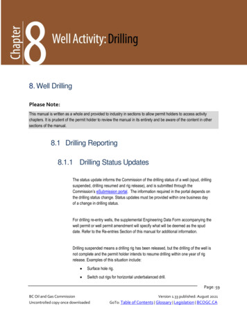
MAINTENANCE AND LUBRICATIONCAUTION: Shut off power to adjust, service, or clean the machine.CAUTION: Keep all safety shields and devices in place.IMPORTANT: Keep all nuts, fasteners, and fittings properly torqued. Refer totorque chart (inside back cover )for proper assembly torque.RECOMMENDED GREASE:Mobilgrease XHP 462 Molyor equivelant greasecontaining molybdenumNLGI No. 2 GradeGREASE BOLTS:The 3 grease bolts should be greased every 8 hours of operation using therecommended grease. Apply grease through the grease fittings which are accessiblefrom the side of the mast, top and bottom, and the side of the draw-works drive bracket.See Figure 1.SLIDE PADS AND RAILS:The slide pads and rails should be kept clean and free of dirt and grease build-up. Thepads are made of UHMW plastic and do not require lubrication.1/2" x 8" BoltGrease BoltChain TensionerTurnbuckleSwivel HousingEnd CapQuill (Stem)Figure 1Page O-61017
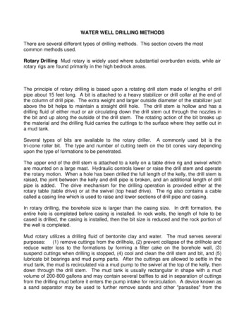
MAINTENANCE AND LUBRICATION CONT.DRIVE CHAIN:The drive chain should be checked for tightness every 4 hours of operation andlubricated if necessary. To adjust, tighten chain tensioner turnbuckle by hand or with theaid of a screwdriver. the chain tensioner turnbuckle is attached to the bottom of theshuttle plate. See figure 1. Tighten the turnbuckle until the chain has very little slack. Ifthe slack cannot be taken up completely, remove a link from the chain. If the chainbecomes dry, lubricate the chain with a heavy weight oil or grease.IMPORTANT: Check the base of the drill mast periodically, around the bottomsprocket, to determine if dirt build-up is present. Clean away the dirt build-up if present.WATER SWIVEL:This machine is equipped with a water swivel which requires regular greasing and adjustment.It is very important to continually monitor the swivel for any leakage of drilling fluid (mud) pastthe seals while drilling. It is critical to stop the leakage as soon as it is detected to preventpermanent damage resulting from abrasive particles in the drilling fluid scoring and erodingthe sealing surface area of the quill (under the seals). Please follow the instructions below toensure best operation.If leakage is detected from the swivel seals:Stop drilling and circulate drilling fluid long enough to clear cuttings from hole. Redirectdrilling fluid to pit or stop mud pump. Pump grease into top and bottom end caps. Seefigure 1. Loosen locking set screws and tighten end caps until leakage stops. Re-tightenlocking set screws.Note: It may be necessary to repeat this process during the drilling operation.If routine greasing and tightening of the end caps fails to stop the leakage, it is time toreplace the swivel seals.Replacing swivel seals:Stop drilling and circulate drilling fluid long enough to clear cuttings from hole. Raise drillhead and remove last joint of drill pipe (see “Tripping Out of the Borehole”). Stop drill engineand lower drill head to a height for easy access to swivel assembly. Be sure to cover drillpipe and borehole to prevent accidental loss of parts or tools.Remove swivel assembly by disconnecting delivery hose and loosen or remove bolt(s) attop of swivel support rod. See figure 2. Support the weight of swivel assembly whileremoving the adapter bolt which attaches the swivel assembly to the hex drive shaft.Remove swivel assembly from drive shaft.1017Page O-7
MAINTENANCE AND LUBRICATION CONT.Loosen the two end caps and slide swivel housing from quill. Remove end caps from swivelhousing. Remove and discard worn seals. Clean and inspect quill for wear in the seal contactareas. If severe wear is present, adjacent surface areas may be used for new seal area whenreassembling.Delivery HoseLocking BoltAdaptor BoltSwivel Support RodLocking SetScrewGrease FittingFigure 2Clean swivel housing and end caps. Install new swivel seals. IMPORTANT: Be surethe small drilled hole in swivel seal is visible above the end of the housing when properly installed(it may be necessary to turn seal over because the holes in the swivel seals are drilled off center).Screw on end caps until snug (do not tighten). Slide swivel housing onto quill and tighten endcaps until the seals grip the quill and begin to resist free rotation. Lock end caps in place withlocking set screws.Attach swivel assembly to hex drive shaft using the adapter bolt. Adjust position ofswivel housing on quill using the swivel support rod and secure in position with lockingbolt.IMPORTANT: Swivel housing should not be resting on hex nut on bottom of quill. Allow atleast 1/8 inch clearance between the bottom end cap and hex nut.Grease new swivel seals with grease gun through grease fittings on each end cap. Greaseshould be seen between quill and end cap when seals have been completely packed with grease.Be aware that it may be necessary to add more grease and/or tighten end caps to prevent mudleakage once drilling resumes.Page O-81017
DRILL PIPE:Always lubricate the drill pipe threads with pipe joint compound before making up eachconnection. After use, clean both male (pin) and female (box) threads with a wire brush toremove dirt and grease residue. Replace the cap on the pin end. Clean all foreign matter fromthe pipe before storing.DRILL BITS:After use, clean the female (box) threads with a wire brush to remove dirt and grease residue.Clean all foreign matter from the bit before storing.CAUTION: NEVER operate drill rig with damaged or missing parts.CAUTION: MAKE SURE EVERYONE IS CLEAR BEFORE OPERATING.CAUTION: Read and understand your operator’s manual for the mud pump.CAUTION: Read and understand your operator’s manual for the engines.CAUTION: Read and understand your operator’s manual for the gear box.1017Page O-9
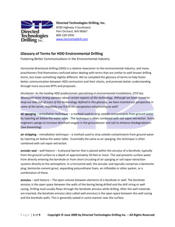
OPERATING INSTRUCTIONS:DANGER: NEVER drill holes where there is a possibility of underground power cablesor other hazards. The exact location of underground services must be determined priorto drilling. Inadvertent severing of telephone, fiber optic or CATV transmission cable, ordamage to sewer pipe is costly; RUPTURING OF GAS OR WATER LINES CANCAUSE SERIOUS BODILY INJURY AND/OR DEATH. COMING INTO CONTACTWITH BURIED POWER LINES CAN CAUSE SERIOUS BODILY INJURY, SEVEREBURNS, AND/OR ELECTROCUTION. Call local utility companies or your local OneCall number at least 48 hours before digging and have underground utilities marked.DANGER: Keep machine and drilling tools away from overhead electric wires anddevices. Electrocution can occur without direct contact. Failure to keep away will resultin serious injury and/or death.DANGER: NEVER run engine inside building or enclosed area. Exhaust gases containcarbon monoxide, an odorless and deadly poison.PRE-DRILLING SETUP:Site Preparation:Select a site that is suitable to safe operation of the equipment. It should be as level as possibleso that the rig can be set up and leveled with minimal cribbing and the operator and helpers willhave safe footing at all times. The mud pits should be positioned down-slope from the rig.Drill HeadDrill MastDrill TableStabilizer TubesFigure 3Page O-101017
OPERATING INSTRUCTIONS Cont.:Rig Assembly:Assemble drill table, stabilizer tubes, and drill mast. See figure 3. To reduce potential settling,2 x 6 boards may be placed under stabilizer tubes. Increased stability may be gained byattaching three ropes (guys) to top of drill mast and anchor to stakes positioned evenly arounddrill rig. Level the drill rig using a level on two adjacent surfaces of drill mast (it may benecessary to adjust by digging out high spots). Attach drill head using two ½” x 8” bolts.Position mud pump near the suction pit and lay out mud hoses. Connect the mud hoses. Thehose from the center of the 3-way valve connects to the mud pump discharge (top side); thehose from the bottom of the 3-way valve connects to the mud mixer. Position mud mixer todischarge into settling pit and anchor by driving spike. The suction hose with foot valveconnects to the mud pump suction inlet.CAUTION: Read and understand the operator’s manual for the engine and gearbox ofthe drill head.DRILL HEAD CONTROLS:The engine of the drill head is equipped with a centrifugal clutch which disengagesrotary at low rpm (idle) and engages rotary at high rpm. Use throttle to control rotary speedwhen making pipe connections. However, while drilling, maximum rotary speed (full throttle)should be maintained.The winch is used to raise and lower the drill head. While drilling, maintain slight backpressure on winch handle. Do not allow the handle to make one revolution in less than 20seconds. This maximum speed will allow cuttings to be flushed from hole even when drilling isrelatively easy. Drilling speeds will be greatly reduced in harder formations.DRILLING PROCEDURE:CAUTION: Keep all safety shields and devices in place.CAUTION: Make certain everyone is clear before operating.CAUTION: Read and understand the operator’s manual for the mud pump.Before starting the mud pump, place the 3-way valve in the bypass position. Fill the pits, primethe mud pump and start the mud pump by following the procedures found in the mud pumpoperator’s manual. Let it run until good circulation is established.Raise the drill head to a convenient height to pull the engine starting rope and start engine.Raise drill head to within 6" of the top stops. Be careful not to jam the shuttle plate into thestops, either top or bottom, as this can cause undue stress on the draw-works drive componentsand the mast. Apply pipe joint compound to the threads of the swivel stem, the first drill pipe,and the bit. Screw the drill pipe onto the swivel stem by hand, then slowly lower the pipethrough the slip plate. Screw the bit onto the end of the pipe by hand.1017Page O-11
DRILLING PROCEDURE Cont.:To start drilling, lower the rotary drive head until the bit just contacts the ground. Place the 3way valve in the drilling position so that drilling fluid flows out the bit. Increase engine speed toengage clutch and allow bit to begin rotating.Use the winch to control the rate of feed of the drill bit. Be careful not to move it too fast or the bitcan become plugged. While drilling, maintain slight back pressure on winch handle. Do notallow the handle to make one revolution in less than 20 seconds. This maximum speed willallow cuttings to be flushed from hole even when drilling is relatively easy. Drilling speeds willbe greatly reduced in harder formations. Monitor the cuttings to make sure the feed rate iscorrect for the type of soil being cut. Harder soils will require more feed force.Continue drilling the pipe down until the drill head comes to the bottom of its travel. Move theslip plate to allow the top of the drill pipe to go about 2 inches below the top of the drill table.Continue circulating drilling mud and let the drill head remain at the bottom for an adequatetime to allow the cuttings to clear. Rotation may be stopped by reducing throttle to idle. Monitorthe up-hole flow to determine when all the cuttings have been removed. Failure to adequatelyclear the cuttings may result in the bit being trapped as the cuttings fall to the bottom of the holewhen the fluid flow is diverted.Raise the rotary drive head far enough to allow the slip plate to fit around the drill pipe. It maybe necessary to rotate drill pipe in order to position the breakout lugs in line with the opening inthe slip plate, then lower the drill head so that the bottom of the tool joint is 1-1/2" above the slipplate. This distance will allow the drill pipe to be unscrewed from quill as the slip plateengages the breakout lugs top prevent the drill pipe from turning.Place the 3-way valve in the bypass position to divert the flow of drilling fluid back to the pits.Use the large hex wrench to unscrew quill from the top of the drill pipe (allow lugs on wrench torest on quill hex). The swivel stem pin (male thread) will “break out” of the drill pipe and whenthe pipe is completely unscrewed it will drop free and fall into the slip plate. Carefully followingthis procedure will ensure that the threads of the swivel stem and drill pipe remain undamaged.NOTE: If the drill pipe fails to drop free of swivel stem pin then the cuttings were notcompletely removed from the hole.ADDING PIPE:- Raise the rotary drive head to the top of the mast, stopping at least 1" below the top stop.- Apply pipe joint compound to the threads of the swivel stem and the drill pipe.- Screw the new pipe into the box threads of the pipe resting in the slip plate. Don’t completelytighten. Position the swivel stem threads about 1/2" above the top of the new pipe.- Increase engine speed until quill starts to slowly rotate.- Slowly lower drill head with swivel stem threads rotating as the threads start to engage. It maybe necessary to have a helper hold the pipe to position it in alignment with the swivel stemthreads.- Continue to let the drill head move downward as the threads, both top and bottom set, “makeup”.Page O-121017
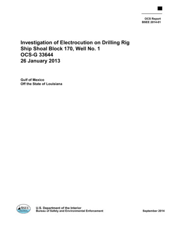
- Just as the threads begin to tighten (both top and bottom sets) Reduce engine speed to idle tostop rotaion.- Raise the drill head and pipe string so that the slip plate may be removed.- Place the 3-way valve in the drilling position, wait to make sure circulation is re-establishedand fluid comes out the borehole, and continue as above.COMPLETING THE BOREHOLE:When the borehole is completed to the required depth, the drill pipe should be removed. Besure to allow time for the drilling fluid to circulate and completely clear the hole of cuttings.Monitor the outflow to determine when the hole is clear.COMING OUT (TRIPPING OUT):NOTE: Coming out of the borehole should be done quickly to minimize the possibility ofthe borehole collapsing.NOTE: This is the time when drill pipe is most likely to be dropped down the hole.Follow these steps carefully to prevent this from happening.- Place the 3-way valve in the bypass position. The mud pump is no longer needed and can beshut off.For M50 Pipe (LS100)1. Raise the drill head far enough to allow slip plate to be pushed around the drill pipe closestto swivel. See Figure 4. Insert a C-wrench below the tool joint and on top of the slip plate (thiswill allow pipe to be lifted with C-wrench once connection with quill is broken). The bottom oftool joint should be at least 1” above C-wrench.2. Use hex wrench to unscrew quill from top of drill pipe (allow lugs on wrench to rest on quillhex). When the quill is unscrewed sufficiently, the drill pipe should drop down onto the Cwrench.3. Raise the drill head to height where it can be swiveled above the 3-way valve. Remove oneof the hinge bolts, pivot the drill head, and secure it out of the way.IMPORTANT: Keep back as vertical as possible by bending legs, as required, during the liftingprocedure.Figure 41017Page O-13
4. Three people are required to remove the pipe from the hole. Two people will use the Cwrenches to lift the pipe. The third person will work the slip plate and coordinate the lifting.The first person begins by using the C-wrench, which is under the tool joint, to lift the pipe off ofthe slip plate. The second person slips the other C-wrench under the first person’s C-wrenchas soon as there is room to do so and helps lift the pipe. Together they lift only a short stroke bystraightening their legs until the third person stops the lift by saying “HOLD”.5. The first person (with C-wrench on top) takes full weight of drill pipe and says “I HAVE”.6. At this signal, the second person (with C-wrench on bottom) relaxes and slides their Cwrench down to get a new grip (without disengaging the wrench from around pipe) and whenready to take full weight of pipe says “I HAVE”.7. At this signal, the first person (with C-wrench on top) relaxes and slides their C-wrench downto get a new grip (without disengaging the wrench from around pipe) and when ready to takeweight of pipe says “LIFT”.8. Together they lift only a short stroke by straightening their legs until the third person stopsthe lift by saying “HOLD”.9. Repeat steps 5 through 8 until the next tool joint is about to reach the slip plate. The thirdperson pulls the slip plate out of the way only when tool joint can be lifted clear in one stroke.In this way, the slip plate can be pushed back around the drill pipe immediately after tool jointis lifted above table.10. The first person (with C-wrench on top) takes full weight of drill pipe and says “I HAVE”.11. At this signal, the second person (with C-wrench on bottom) relaxes and slides their Cwrench down to get a new grip below the next tool joint (must briefly disengage wrench fromaround pipe to do this). When the second person (with C-wrench on bottom) is ready to takefull weight of pipe, they say “DOWN”.12. Together, they lower weight of the pipe onto the slip plate with a C-wrench underneath thetool joint. Note: If lugs on pipe do not line up with the slot of slip plate, the pipe will need tobe lifted and rotated until lugs line up and pipe may be lowered onto slip plate with the bottomC-wrench underneath the tool joint.13. Break threaded connection by using 24” pipe wrench (and aid of sharp hammer blow ifconnection is too tight).14. Remove drill pipe by unscrewing by hand.15. Repeat steps 4 through 14 until all drill pipe and bit is pulled from the borehole. If possible,bring the bit up through the slip plate and then replace the slip underneath before unscrewingthe last pipe and bit. Place a cover over the borehole to protect it from falling objects until thecasing is ready to be placed.Page O-141017
For M250 Pipe (LS200)1. Raise the drill head far enough to allow slip plate to be pushed around the drill pipe closestto swivel. The bottom of tool joint should be at least 1” above slip plate.2. Use hex wrench to unscrew quill from top of drill pipe (allow lugs on wrench to rest on quillhex). When the quill is unscrewed sufficiently, the drill pipe should drop down onto the slipplate.3. Raise the drill head to height where it can be removed. Remove the hinge bolts to removethe drill head. Attach hoist bracket assembly to shuttle plate using the hinge bolts as shown infigure 5.Hoist BracketFigure 5Hoist Plug4. Connect hoist plug to top of drill pipe by hand.NOTE: Make sure the threads are adequately engaged. Failure to do so can result inthe pipe dropping off the hoist plug.5. Lower hoist bracket assembly to connect hook to hoist plug.6. Lift drill pipe by raising the hoist bracket.7. Raise the hoist bracket far enough to allow slip plate to be pushed around the next drill pipe.Lower hoist bracket until bottom of tool joint is resting on slip plate.8. Break threaded connection by using 24” pipe wrench (and aid of sharp hammer blow ifconnection is too tight).9. Remove drill pipe by unscrewing by hand.10. Repeat steps 4 through 9 until all drill pipe and bit is pulled from the borehole. If possible,bring the bit up through the slip plate and then replace the slip underneath before unscrewingthe last pipe and bit. Place a cover over the borehole to protect it from falling objects until thecasing is ready to be placed.1017Page O-15
NOTES:
IMPORTANT: All nuts, fasteners, and fittings must be kept tightened. Refer totorque chart for proper assembly torque.HEX HEADTYPEGRADE5GRADE8WRENCH SIZEWRENCH SIZEinchSIZENo. 48 in lb12 in lb1/4"12 in lb3/32"No. 616 in lb23 in lb5/16"21 in lb7/64"No. 830 in lb41 in lb11/32"42 in lb9/64"No.1043 in lb60 in lb3/8"60 in lb5/32"1/4"8 ft lb12 ft lb7/16"12 ft lb3/16"5/16"17 ft lb25 ft lb1/2"24 ft lb1/4"3/8"30 ft lb45 ft lb9/16"43 ft lb5/16"7/16"50 ft lb70 ft lb5/8"69 ft lb3/8"1/2"75 ft lb110 ft lb3/4"105 ft lb3/8"9/16"110 ft lb150 ft lb13/16"158 ft lb-----5/8"150 ft lb220 ft lb15/16"195 ft lb1/2"3/4"260 ft lb380 ft lb1-1/8"353 ft lb5/8"HYDRAULIC FITTINGS1017SIZETORQUE1/4 NPT3/8 NPT1/2 NPT3/4 NPT25 ft.lb.50 ft.lb75 ft.lb.110 ft.lb.SIZE7/16-209/16-183/4-167/8-141-1/16-12SAE O-RingSAE O-RingSAE O-RingSAE O-RingSAE O-RingTORQUE12 ft.lb.20 ft.lb.35 ft.lb.50 ft.lb.70 ft.lb.
TH IN KS AFE T YFI R S T!P.O. BOX 840LIVINGSTON, TEXAS 77351PHONE 936/327-3121FAX 936/327-4025Web: www.littlebeaver.comE-Mail: sales@littlebeaver.com
Recommended Drilling Equipment Set‐up
03763025332262991035361ITEM QTY PART NUMBER11 LS200TBA1 LS200MW21 LS200WA341 9-3651151 LS200MISAM62 LS200MISACB71 FC1006965381 7342792 FC100696541 7342710111 DL70328121 LS200SHUT132 LS200-023142 LS200-024154 BPL100521161 70133171 701341 7013518192 GR6L092201 FEA7060801211 LS100CHA222 FC132302310 KT0302410 70306253 3012-2263 3002-B273 30154282 70199291 702271 7042230312 KT055322 3012-1T332 303181 LS200RPUHA341 LS100RPUHA34341 LS200HDRPUA1 LS100HDRPUA34352 LS100SLT361 LS200SLPA361 LS100SLPA4 653237BASIC RIG PARTS LISTDESCRIPTIONTABLE BASE ASSEMBLYMAST WELDMENTWINCH ASSEMBLY (INCLUDES DL70328)ROLLER CHAIN, #50MAST IDLER SPROCKETMAST IDLER SPROCKET, ENDSGREASE BOLT, 1/2 X 4 (INCLUDES 73427)GREASE FITTING, 3/16 DRIVEGREASE BOLT, 1/2 X 3-1/2 (INCLUDES 73427)GREASE FITTING, 3/16 DRIVEDL2500B WINCH HANDLESHUTTLE PLATECOVER PLATE, WEAR PADSPACER PLATE, WEAR PADUHMW WEAR PADCHAIN TENSIONER, 1/2"CHAIN ADJUSTER BOLT, 1/2"ANCHOR, CHAIN, #50CONNECTING LINK, #502" 3-WAY BALL VALVECROWN HANDLE ASSEMBLYBOLT, HEX, 1/2 X 8-1/2BOLT, HEX, 3/8 X 1-3/4, NC GR.5WASHER, INTERNAL STAR LOCK, 3/8BOLT, HEX, 3/8 X 1, NC GR.5WASHER. FLAT, 3/8 SAENUT, HEX, 3/8 NC, NYLON LOCKBOLT, HEX. 3/8 X 3/4, NC GR.5NIPPLE, CLOSE, 2"HANDLE EXTENSIONNUT, HEX, 1/2 TOP LOCKBOLT, HEX, 5/16 X 3/4, NC GR.5NUT, HEX, 5/16 NYLON LOCKHONDA ROTARY POWER UNIT FOR LS200HONDA ROTARY POWER UNIT FOR LS100HATZ ROTARY POWER UNIT FOR LS200HATZ ROTARY POWER UNIT FOR LS100TUBE, STABILIZERDRILL PIPE SLIP, M250DRILL PIPE SLIP, M50BOLT, HEX, 1/2 X 2, NC GR.5LS200BRP-D Basic Rig, DieselLS100BRP-D Basic Rig, DieselLS200BRP-D Basic Rig, DieselLS100BRP-D Basic Rig, DieselLS200BRP-G Basic Rig, Gasoline (Petrol)LS100BRP-G Basic Rig, Gasoline (Petrol)LS200BRP-G Basic Rig, Gasoline (Petrol)LS100BRP-G Basic Rig, Gasoline
O-11, O-12, O-13, O-14 & O-15 Drilling Procedure Scope of Manual This manual is intended to provide instruction in the safe operation of the drill rig. It is not a complete well drilling reference. Additional information on siting, drilling and completing a water well can be found in the LIFEWATER DRILLING AND WELL CONSTRUCTION REFERENCE MANUAL.