Transcription
Available online at www.sciencedirect.comScienceDirectProcedia Engineering 73 (2014) 337 – 344Geological Engineering Drilling Technology Conference (IGEDTC), New InternationalConvention Exposition Center Chengdu Century City on 23rd-25th May 2014Study on Well Control Technology of High TemperatureGeothermal DrillingZhang Delonga* Jia Juna Huang Yuwena Weng Weia Zhu WenjianaaBeijing Institute of Exploration Engineering, BeiJing 100083, ChinaAbstractWith the rapid development and research of geothermal resources, the number, drilling depth and formation temperature of hightemperature geothermal wells increases year by year. But, so far the well control technology of high temperature geothermaldrilling has not been paid attention to by relative person, the serious shortage of related technology and equipments retards thedevelopment of geothermal resources. This article describes the calculating methods of formation pressure, collapse pressure,circulating temperature, saturation vapor pressure and mud circulating temperature in high temperature geothermal wells, it canoffer reference data for the design of drilling fluid, bottom hole assembly (BHA), well control equipment. High temperaturegeothermal drilling depends on the formation pressure and collapse pressure, the safe mud window is very narrow, suitable forpressure balance or underbalanced drilling, we design a simple structure, high speed, good heat resistance rotary blowoutpreventer (RBOP), which can increase the operability of geothermal wells balanced drilling. Authors.by ElsevierLtd.under CC BY-NC-ND license. 20142014 ThePublishedby PublishedElsevier Ltd.Open accessSelectionSelection andand s: Geothermal drilling, Well control, RBOP, Balanced DrillingIn the geothermal wells drilling process, the annulus hydrostatic column is usually higher than the pore pressure,two situations that can cause geothermal well blowout: circulating hot fluids from deeper depths to the surface,resulting in the fluids flashing to steam, which causes a loss in hydrostatic pressure, and a further flashing or boildown effect; or lost circulation causes the fluid level, and thus the pressure, in the wellbore to suddenly fall farenough for the same thing to happen [1].Well control, in general, has to do with preventing the flow of formation fluids into the wellbore and safelyremoving them if they get into the wellbore, ensuring safety in drilling operation. The well control measures must be* Corresponding author. Tel.: 8615910697861.E-mail address: tgszdl@126.com1877-7058 2014 Published by Elsevier Ltd. Open access under CC BY-NC-ND license.Selection and peer-review under responsibility of Geological Engineering Drilling Technologydoi:10.1016/j.proeng.2014.06.207
338Zhang Delong et al. / Procedia Engineering 73 (2014) 337 – 344taken quickly in the event of a kick, if control is lost, a large number of high-temperature drilling fluid, formationfluid and gas (sometimes contains toxic gases) would flow into the wellbore then blow out from the wellhead, theresulting disaster is a “blowout” which, at the least will be very expensive and, at worst, can result in loss of life,equipment, and the drill rig, as well as damage to the environment[1]. It occurred in Nevada and Hawaii hightemperature geothermal wells drilling process [2 3] .With the development of high-temperature geothermal resources, the geothermal well’s number, drilling depthand formation temperature are gradually increased. Most of the current well control equipments and measures areagainst oil drilling, it is and always neglected in high temperature geothermal drilling. In this case, in order to ensurethe life and property safety, promote the development of high-temperature geothermal resources, it is verymeaningful to study of well control technology and equipments of high-temperature geothermal drilling.1. Present Situation of Geothermal Drilling Well ControlWell control technology has made a good development and application in the oil and gas drilling operation , wellcontrol equipment generally includes BOP stack, BOP control device, choke and kill manifold, inside BOP, mudweighting equipments, mud filling line, gas separator, monitoring instruments, etc., it also developed a well controlsoftware. The BOP stack is the combination of one or more RBOP, ram preventer, annular BOP, universal BOP.At present, ram BOP is the most common equipment in high-temperature foreign geothermal drilling, minoritychose RBOP as the primary well control equipment; in China, ram BOP is generally used in high temperaturegeothermal drilling, but some geothermal drilling site is not equipped with well control equipment, and there are noapplication of RBOP in geothermal drilling, the reasons are mainly the following:(1) High cost. RBOP is more expensive than any other BOPs.(2) Larger size. Existing products are mainly used in petroleum drilling in domestic, the geothermal well site areaand equipment capacity is always smaller than oil drilling, as shown in Table. pressureWilliams7100Table. 1 comparison of rotating BOP performanceDynamic PressureStatic PressureMax tt 50872015015551802FX28-3517.53510014442801(3) Poor heat resistance ability. Existing domestic BOP operating temperature usually does not exceed 150 ć,and the bottom hole temperature of high-temperature geothermal wells is usually higher than 150 ć, the existingRBOP can meet the requirements.(4) Low rated speed. Domestic geothermal drilling rig usually chosen hydrogeological water well drilling rig,which working speed is usually above 200r/min, while the existing RBOP’s maximum speed is lower than 200 r/min.Comparing the domestic and foreign well control equipments, it can be found that domestic technology andequipments lags behind foreign countries, the awareness of the importance of well control is obviously insufficient.Therefore, based on the characteristics of high temperature geothermal drilling, to develop a simple structure, highspeed, small size, low cost, high temperature capability well control equipments has good market prospect andpractical significance.
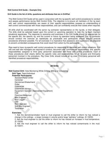
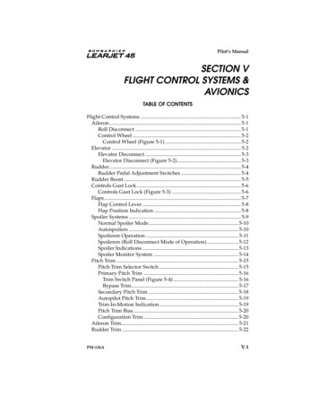
Zhang Delong et al. / Procedia Engineering 73 (2014) 337 – 3443392. Illustrations2.1. Temperature of High Temperature Geothermal DrillingThe difference between geothermal wells and oil wells is that geothermal drilling is characterized by high bottomhole temperature, it is usually higher than 150 C, and even higher than 300 C in hot dry rock formations. Thecirculating temperature directly affects the rheology, density, chemical stability of drilling fluids, the performancechanges of drilling fluid has a significant effect in pressure balance and circulating pressure loss[4]. When kick orblowout occurs, the high temperature formation fluid flows into the wellbore and quickly jet out of the wellbore, atthis time the temperature of is inevitably higher than normal drilling fluid circulation temperature, so well controlequipment requires better high temperature properties. Therefore it is requested that the well-control equipment havea higher temperature property. So it is very important to calculate the circulating temperature accurately for wellcontrol equipments designing.2.2. Calculation Method of Circulating TemperatureWhile circulating, heat transfer occurs between formations, drilling fluid, formation fluids and drilling pipes inboth horizontal and vertical directions. The temperature distribution of drilling fluids depends on depth, thermalconductivity of drilling fluid and the rock, drilling fluid flow rate, inlet temperature, temperature gradient of rocks,and many other factors, the temperature distribution will change by the changing of any one of the factors [5]. Atpresent, the commonly used calculation methods are down hole measurement method, simple estimation method andcomputer simulation method. Down hole measurement method is most accurate and costly, usually used incomplicated well condition; simple estimation method cannot give an accurate result; computer simulation methodis based on the energy conservation principle, it is characterized by high computing speed and low cost, cancalculate the static and transient temperature, its process is firstly establishing mathematical model of thetemperature distribution of the drilling fluid, secondly solving the model with computer, then simulating thetemperature distribution of drilling fluid[6].Following is conservation equations of drilling fluid circulation system (contains drilling fluid, drilling pipes,casings, cement sheath and formation) [7] :డఘడ ሺߩ ݒ ௭ ሻ ൌ Ͳ(1)డ௧డ௭డሺఘ௩ ሻ డሺߩ ݒ ௭ ݒ ௭ ሻ ൌ െడ௧డ௭డቀఘ ்ቁడడ௧ ்ܵ ൌ ߩܶడ ௧ቀߩ ݒ ௭ ܶቁ ൌఒడ డ௭(2)െ ߩ݂௭ଵ డ൬ ఒ డఘ ் డ డ ൰ డെ ߘ ή ൬ ߘܿ ൰ ݍ ௦ ݍ ݍ ൬ఒ డఘ ்൰డ௭డ ்ܵ(3)(4)Formula (1) is the one-dimensional flow mass conservation equation of drilling fluid, ߩ is the mass density,ߩ ൌ ߩሺ ݐ ǡ ݖ ሻ; ݒ ௭ is axial velocity of drilling fluid in the drill string or annulus; ݐ is time.Formula (2) is the one-dimensional flow energy conservation equation of drilling fluid, is pressure; ispressure drop gradient of drilling fluid, ݂௭ is z component of the per unit mass force of the drilling fluid.Formula (3), (4) is the energy conservation equation of wellbore system, ܿ is the specific heat of the medium,ܿ ൌ ܿ ሺ ݐ ǡ ݎ ǡ ݖ ሻ, ߣ is the thermal conductivity of the medium, ߣ ൌ ߣሺ ݐ ǡ ݎ ǡ ݖ ሻ; ܶ is temperature, ܶ ൌ ܶሺ ݐ ǡ ݎ ǡ ݖ ሻ; ݍ ௦ isthe heat sources of per unit volume computational domain such as heat generated by rotating drill string and bit, drillnozzles pressure drop heat, etc. ݍ is the heat generated by pressure drop of per unit volume drilling fluid; ୧୬ is theheat inflow into drilling fluid from drill strings and wall of the borehole.When the boundary conditions are given, the equations can be simplified and solved. Following is atemperature distribution graph of drilling fluid in a well.
340Zhang Delong et al. / Procedia Engineering 73 (2014) 337 – 344Fig. 1 Diagram of Circulating Temperature 3. Calculation Method of Circulating PressureConventional drilling well control method is to maintain the wellbore pressure higher than the pore pressure ofthe formation. In high temperature geothermal drilling, the formations are usually characterized by high temperatureand low pore pressure, drilling fluid leakage is the most common costly down hole accident, the cost of dealing withleakage accounts for 10% of the whole project [8].Further, the circulating temperature of geothermal well is higher, once the fluid column pressure is lower than thesaturated vapor pressure, the high temperature fluid vaporization will occurs, lots of steam will blowout of the hole.Drilling fluid vaporization will lead to further drop of the annulus pressure, causing deeper vaporization and annuluspressure drop, if it cannot be controlled effectively, collapse, well blowout and other serious drilling accident willoccur.In order to reduce drilling risk, reduce costs, and protect the reservoir, the best way is to use near balanced orunderbalanced drilling technology. As early as 1979, the lightweight mud had been used to prevent leakage in hightemperature geothermal wells drilling in America [1] . As the formation pressure is higher than the annulus pressure,there are risks of well kick and blowout, so the core work of near balanced or underbalanced drilling is pressurecontrol. In high temperature geothermal drilling, accurately estimating pore pressure, fracture pressure and collapsepressure is a necessary precondition for well control designing.3.1. Formation PressureFormation pressure usually refers to the formation pore pressure, which is calculated by the relationship betweenthe drilling can be divided into: prediction before drilling, measurement while drilling, logging detection [9] .Prediction before drilling: Earthquake prediction is the main way to know formation pressure, the processincludes: ķ establish velocity curve of normal compaction formation; ĸ analysis of seismic velocity anomalies,establish relationship of abnormal formation pressure and velocity; Ĺ predict formation pressure.Measurement while drilling: Drilling data analysis methods, calculating formation pressure with drilling data.Commonly used methods are shale cuttings density method, dc-exponent method, returning mud temperature, ROPmethod, etc., dc-exponent method is the most representative method, the accuracy of this method depends on WOB,ROP, drilling-time, bit diameter, fluid density and normal formation pressure.Logging detection: The effect of sonic logging than the density logging, resistivity logging by boreholes, groundconditions and other factors, small and complete information, the use of sound waves to detect pore pressuredifference representative and universality.Logging detection: Compared to the density and resistivity logging, sonic logging data is complete and lessaffected by borehole and formation, using acoustic transit time to detect pore pressure is representative and universal.
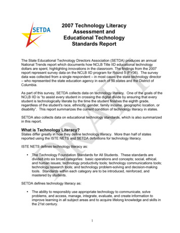
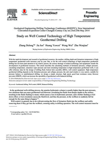
Zhang Delong et al. / Procedia Engineering 73 (2014) 337 – 3443413.2. Collapse PressureThe wall of borehole suffers tangential and radial stresses, when the difference between the two stresses reaches acertain value, it will cause rock shear failure which would result in the collapse of the borehole, at this point thedrilling fluid column pressure is the borehole collapse pressure [10] . The formula is as follows: ܤ ൌఎ൫ଷఙಹ ିఙ ൯ିଶఛ ା ൫ మ ିଵ൯ሺ మ ାఎሻ(5)In this formula, ܤ is borehole collapse pressure; ɐୌ ,ɐ୮ is the maximum and minimum horizontal principalstress; ൌ ିଵ ሺɎȀͶ െ ȰȀʹሻ, Ȱ is internal friction angle;߬ is rock cohesion; ܽ is Biot elastic constants; ܲ is porepressure of the formation; Ʉ is stress non-linear correction coefficient.3.3. Saturated Water Vapor PressureThere is standard values of saturated water vapor pressure, which can be refer to while calculating water-baseddrilling fluid saturation vapor pressure, a rough calculation can only use the following formula:ర(6)ܶ ൌ ͳͲͲ ൈ ξͳͲܲIn this formula: P is the saturated vapor pressure; T is temperature.3.4. Circulating Pressurehe value of bottom hole pressure directly affects the inflow volume of formation fluids, drilling safety andefficiency. Bottom hole pressure is the sum of circulating pressure loss, inflowing formation fluid pressure, surgepressure, swabbing pressure, ground back pressure. The following is a method of calculating bottom hole pressureunder different operating states [10] :Stationary annulus hydrostatic pressure;Circulation drilling annulus hydrostatic pressure circulating pressure loss;Drilling with RBOP annulus hydrostatic pressure circulating pressure loss RBOP back pressure;Circulating drilling fluid annulus hydrostatic pressure annulus pressure loss throttle resistance pressure;Tripping out annulus hydrostatic pressure swabbing pressure;Tripping in annulus hydrostatic pressure surge pressure;Shutting well annulus hydrostatic pressure ground back pressure.4. EquationsWellhead equipments selecting mainly considers formations pressure, devices height, formation fluids types andother factors. According to the characteristics of high-temperature geothermal wells, the suitable wellheadequipments are: casing head, drilling spool, single ram BOP, RBOP, choke line, etc. (Fig. 2).BOP stack selecting mainly considers: well type, formation pressure, casing size, formation fluids type, technicalcondition, technology requirements, climate, transportation, supplies status, and environmental protectionrequirements. According to the characteristics of high-temperature geothermal wells, the suitable BOP stack iscombined utilization of single ram BOP and RBOP.4.1. New RBOPCurrent RBOP is extensively used in oil and gas drilling, it achieves sealing with interference fit between thedrilling pipe and rubber seal. It is characterized by high pressure capability, bulky weight, low rotating speed, lowtemperature capability. High temperature geothermal drilling is characterized by high rotating speed, highcirculating temperature, and smaller size drilling equipments, therefore it need to be equipped with small size, lightweight, high rotating speed, and good temperature capability RBOP, which should be simple structure, operatingflexibly and low cost.
342Zhang Delong et al. / Procedia Engineering 73 (2014) 337 – 344Fig. 2 Diagram of Wellhead Devices 4.2. Parameters Design of RBOP(1) Operating temperatureAccording to their occurrence, geothermal resources can be categorized into hydrothermal type, hot dry rockresource and ground-pressure resource, the formation temperature of hot dry rock reservoir is usually above 300 ć.To ensure the safety of drilling, the temperature capability of RBOP should not be less than 200 ć.(2) Rated speedDue to the large hole size of oil wells, the rotation speed of drilling pipe is usually less 200 r/min; the hole size ofgeothermal wells are smaller, the rotation speed is usually not less than 200 r/min during normal drilling.Considering the characteristics of geological drilling equipments, it is determined that the rated speed of RBOP is300 r/min.(3) Rated pressureSaturated vapor pressure changes with temperature, under the condition of 200ć, the water saturated vaporpressure is 1.555MPa. In addition, while the annulus hydrostatic pressure is lower than the bottom hole pressure,RBOP usually bears some of the pressure, so in order to meet the needs of near balanced or underbalanced drilling,the RBOP is designed to bear 3.5MPa dynamic pressure and 7MPa static pressure.(4) Nominal sizeAccording to the geothermal wells drilling and completion requirements, the normal size of RBOP is determinedto be 230mm.4.3. Structure DesigningAccording to current RBOPs usage and problems, it is concluded that the key points of RBOP structure designingare rubber seal, rotary dynamic sealing and selection of high-speed bearings. Therefore, more attention should bepaid to the designing of these three main aspects.(1) Rubber seal designingCurrently, the main seal types are conical annular rubber seal and spherical capsule rubber seal. The conicalannular rubber seal is long life and simple structure; the spherical capsule rubber seal is complicated, it can sealdifferent sizes of pipe through changing the pressure of a single hydraulic source. Based on analysis of theadvantages and disadvantages of the two types, considering domestic actual production situation and RBOP’spressure capability, the conical annular rubber seal is selected. The structure of RBOP is as follows:
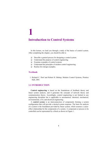
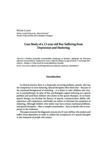
343Zhang Delong et al. / Procedia Engineering 73 (2014) 337 – 344 Fig. 3 Structure Drawing of RBOP(2) Bowl designingThe bowl is a key component of RBOP, whose upper connects to rotating assembly, interior includes center tube,rubber seal and other components, and on one side of it there is a hole for drilling fluid circulation. Considerationthe requirements of production and maintenance, it is determined that: the bottom connection form is flange, the topis designed to be connected to the rotating assembly with clamp connection (Fig. 3).According to the parameters of RBOP, the dynamic pressure is 3.5MPa while working, so it is considered to be apressure vessel withstanding hydrostatic 5MPa. In the case, the design principles are consistent with pressure vessels.(3) Bottom flange designingThe basic requirement for flange is to ensure long-term safety of the RBOP; also the simple structure and easyaccessibility are important. It is determined that the structure of the bottom flange is an integral flange (Fig. 4),which is cast together with the bowl, this arrangement ensures that the bowl and the flange endure the force together,the overall structural strength is improved. Fig. 4 Structure Drawing of the Integral Flange(4) Center tube designingAs a key component of RBOP, the center tube rotates with the rotating assembly and rubber seal duringworking, it withstands high internal pressure. The wall thickness of center tube is very important and must bestrength checked.For the hollow rotating shaft which calculated as:݀ ൌ ʹͳǤ ͺඨඥெమ ାሺఝ்ሻమఙషభ ൈయଵඥଵି ర(7)In the formula: ݀ is shaft diameter; ܯ is the bending moment suffered on the computing cross section; ܶ is thetorque suffered on the computing cross section ߮ is a correction coefficient.(5) Rotating assembly designingFrom top to bottom, rotating assembly includes slip assembly, bearing assembly, rubber seal and others.Bearing assembly includes bearings, seals, inside and outside bearing supports and other auxiliary parts. Therotating assembly is rotating with kelly while working. It contains two self-aligning thrust roller bearings, whichboth bear axial force and unbalanced radial force.(6) High temperature and high pressure rotary dynamic seal designThe deflection-type lip seal is selected as the high temperature and high pressure rotary dynamic seal (Fig. 5),
344Zhang Delong et al. / Procedia Engineering 73 (2014) 337 – 344the average sealing pressure is 14MPa, and the life time is above 1,450 hours at speed of 600rpm, which can fullymeet the needs of the site. Fig. 5 Structure Drawing of Deflection-type Lip Seal5. Conclusion(1) Development of high-temperature geothermal resources is accelerating, but the relevant drilling technologyand equipments are lagging behind, it is necessary to study near balanced and underbalanced drilling technology,and develop new suitable well control equipment and down hole tools.(2) Circulating temperature and pressure of geothermal wells are important to drilling safety and efficiency, forthe present relevant studies is scarce.(3) RBOP has been widely used in high-temperature geothermal wells in foreign countries, but there is no RBOPapplication case in China geothermal drilling. In order to ensure the drilling safety and efficiency, it is important toincrease the development and application speed of RBOP.(4) In this paper, we designed a simple structure, high speed, good temperature capability RBOP, which canincrease the operability of geothermal wells balanced drilling.References[1] Finger J, Blankenship D. Handbook of Best Practices for Geothermal Drilling[M]. Sandia National Laboratories,2010;[2] New Scientist(1991)Blowout blights future of Hawaii's geothermal power,1991,issue 1778;[3] Guo Wenzhi, Liu Guangzhi(translation). West Germany Urach III, hot dry rock exploration well drilling and completion technology [J].Proceedings Of The International Conference On Geothermal Drilling And Completion Technology, Jan 21-23,1981;[4] Hu Jiliang, Tao Shixian, Shan Wenjun, Liu Sanyi. Overview of ultra-deep well high-temperature drilling fluid technology and discussion ofits research direction[J]. Geology and Exploration,2012,48(1):155-159;[5] Yi Can, Yan Zhenlai, Guo Lei. Numerical Simulation of Circulating Temperature and Its Impacting Parameters [J]. Petroleum DrillingTechniques,2007,35(6):47-49;[6] He Shiming, He Ping, Yin Cheng, et al. A Wellbore Temperature Model & Its Parametric Sensitivity Analysis [J]. Journal of SouthwestPetroleum Institute, 2012, 24(1):57-60.[7] Zhong Bing, Fang Duo, Shi Taihe. New Model To Predict Temperature Distribution During Drilling [J]. Journal of Southwest PetroleumInstitute,1999, 21(4):53-56.[8] Geothermal Technologies Program (GTP), Department of Energy (DOE).21st Century Geothermal Energy: A History of Geothermal EnergyResearch and Development in the United States-Volume 2-Drilling 1976-2006[M]. Progressive Management, 2012:65.[9] Wang Wei, Zhang Hai, Ren Jian, et al. Methods of Formation Pressure Prediction [J]. Inner Mongolia Petrochemical Industry, 2010(5):46-47.[10] Yang Qingli, et al. Oil and Gas Drilling Well Control [M]. Petroleum Industry Press, 2008.
Keywords: Geothermal drilling, Well control, RBOP, Balanced Drilling In the geothermal wells drilling process, the annulus hydrostatic column is usually higher than the pore pressure, . High cost. RBOP is more expensive than any other BOPs. (2) Larger size. Existing products are mainly used in petroleum drilling in domestic, the geothermal .