Transcription
Halliburton Sperry-Sun DOE High TemperatureLWD ProjectFinal ReportRonald L. Spross, AuthorMarch 15, 2005DOE Award #DE-AC26-97FT34175Halliburton Energy Services3000 N. Sam Houston Pkwy. E.Houston, TX 77032
THIS PAGE DELIBERATELY LEFT BLANK2
DisclaimerThis report was prepared as an account of work sponsored by an agencyof the United States Government. Neither the United States Government nor anyagency thereof, nor any of their employees, makes any warranty, express orimplied, or assumes any legal liability or responsibility for the accuracy,completeness, or usefulness of any information, apparatus, product, or processdisclosed, or represents that its use would not infringe privately owned rights.Reference herein to any specific commercial product, process, or service bytrade name, trademark, manufacturer, or otherwise does not necessarilyconstitute or imply its endorsement, recommendation, or favoring by the UnitedStates Government or any agency thereof. The views and opinions of authorsexpressed herein do not necessarily state or reflect those of the United StatesGovernment or any agency thereof.Available to the public from the National Technical Information Service,U.S. Department of Commerce, 5285 Port Royal Road, Springfield, VA 22161;phone orders accepted at (703) 487-4650.3
THIS PAGE DELIBERATELY LEFT BLANK4
AbstractThe objective of this project was to build a high temperature, costeffective, logging while drilling (HT-LWD) system with the ability to operate at175 C with more than 100 hours mean time between failures (MTBF). Such acommercial real-time formation evaluation (FE) system would help operators todrill and produce hydrocarbon resources from moderately deep, hot reservoirswhich otherwise might be uneconomic to drill.The project plan was to combine the existing Sperry-Sun high temperaturedirectional and gamma logging system with lower temperature FE sensors whichwere upgraded to higher temperature operation as part of the project. The projectwas to be completed in two phases. Phase I included the development of the HTsystem, building two complete systems, demonstrating operational capability at175 C and survivability at 200 C in the laboratory, and successfully testing thesystem in two low temperature field tests. Phase II was to test the system in awell with a bottom hole temperature of 175 C.The high temperature FE sensors developed as part of this project includegamma ray (DGR), resistivity (EWR-Phase 4), neutron (CTN), and density (SLD).The existing high temperature pulser and telemetry system was upgraded toaccommodate the data and bandwidth requirements of the additional sensors.Environmental and lifetime testing of system components and modules indicatesthat system life and reliability goals will be substantially exceeded. The systemhas performed well in domestic and international high temperature wells (to175 C). In addition to the sensor modules specified in the project contract, Sperryhas now upgraded other system components to higher temperature as well.These include a LWD sonic sensor (BAT), pressure while drilling sensor (PWD),and a more powerful central system controller (CIM).5
THIS PAGE DELIBERATELY LEFT BLANK6
Table of ContentsDISCLAIMER3ABSTRACT5TABLE OF CONTENTS7EXECUTIVE SUMMARY9Description of Project Objectives and Work Plan9Summary of Accomplishments10Conclusions and Recommendations10PROJECT DESCRIPTION11Project Objectives11Project Background12System Description13Project Tasks and Accomplishments18Field Test Results22Economic and Market Considerations – the Need for LWD24Conclusions and Recommendations27APPENDICES29Acronyms in the Report Body31Figure 1: Log Example32Figure 2: Pulser/Generator/Telemetry/GM/TM33Figure 3: EWR Slim Phase 4 Tool33Figure 4: CTN34Figure 5: Stabilized LithoDensity Tool347
THIS PAGE DELIBERATELY LEFT BLANK8
Executive SummaryDescription of Project Objectives and Work PlanThe overall objective of this project was to build a high temperature, costeffective, logging while drilling (HT-LWD *) system with the ability to operate at175 C with more than 100 hours mean time between failure (MTBF). Such acommercial real-time formation evaluation (FE) system would help operators todrill and produce hydrocarbon resources from deep, hot reservoirs, includingMobile Bay in the GOM, the western GOM, and the deep Austin Chalk , whichotherwise might be uneconomic to drill. The project plan was to leverage theexisting systems of Sperry-Sun – the HT Solar 175† tool and lower temperatureFE sensors including the resistivity and neutron porosity sensors – in thedevelopment of the HT system.The project was to be completed in two phases. Phase I included thedevelopment of the HT system, building two complete systems, demonstratingoperational capability at 175 C and survivability at 200 C in the laboratory, andsuccessfully testing the system in two low temperature field tests. Phase II was totest the system in a well with a bottom hole temperature of 175 C.The original HT-LWD system concept did not include a density sensor, butthe goals of the project were later modified at the request of Sperry-Sun toinclude a density sensor. Consequently, the HT-LWD system has the fullcomplement of services for basic FE.With DOE support, Sperry-Sun has developed and successfully fieldtested each of the key HT-LWD sensors. Sperry-Sun also independentlydeveloped certain complementary modules in parallel to and /or subsequent tothe DOE project, including a HT central interface module (HT-CIM). As a result,Sperry-Sun is currently able to field a complete HT-LWD system with capabilitiesmeeting or exceeding those envisioned in the original proposal. This system isalso able to easily accept additional sensors and services in the future.*†A table of acronyms is in the Appendix of this report.Solar 175 is a registered trademark of Halliburton Energy Services, Inc.9
Summary of AccomplishmentsAmong the more significant accomplishments of the project are thefollowing :1. FE sensors for gamma ray (DGR ‡), resistivity (EWR-Phase 4‡), neutron(CTN‡), and density (SLD‡) logging were developed, lab tested to 175 Coperating, 200 C survival, and field tested.2. Pulser and telemetry systems were upgraded to HT specifications andsuccessfully tested in the lab and field.3. System field testing has demonstrated the system’s performance perrequirements at temperatures from 150 C to 175 C.4. Component and module field testing has indicated that system life goalswill be substantially exceeded. System data from the field are consistentwith this but are as yet too limited to provide a firm validation.5. Additional tool infrastructure / data management modules were developedand tested to 175/200 C.Conclusions and Recommendations1. The HT-LWD project goals were met in that all sensors weredeveloped, and lifetime and field testing were successful.2. The addition of the HT controller module has enabled inclusion ofother sensors in the HT-LWD system, including sonic and pressurewhile drilling sensors. §3. Although a working HT-LWD system has been demonstrated at175 C, higher temperature operation (e.g. 200 C ) may be neededin the near future to seriously address deeper, hotter, harsher gasresources and the geothermal market.4. Other technologies such as silicon on insulator (SOI) and nonscintillating particle detection technologies (e.g., GM tubes) arepossible paths to develop the capability for entering these highertemperature markets.5. Halliburton is monitoring emerging technologies, as well aspursuing internal developments, to meet these future needs.‡Inc.DGR, EWR-Phase 4, CTN, and SLD are trademarks of Halliburton Energy Services,§The HT upgrades of the CIM, sonic, and pressure sensors while drilling tools were alldone at Sperry-Sun’s expense and were outside the scope of this project.10
Project DescriptionProject ObjectivesSperry-Sun Drilling Services understands that DOE’s objective is toincrease the available gas resources and to assist industry in meeting naturalgas production requirements of the nation. Significant deposits of this resourceare believed to be in deep, HT gas prospects such as the deep Austin Chalk andWestern Gulf of Mexico. Accordingly, the objective of this project was to developa high temperature, cost effective, logging while drilling (HT-LWD) system toevaluate and produce these prospects. Logging while drilling has been a keyelement in the drilling of horizontal and multilateral wells. HT LWD tools will be anenabling technology that will bring these drilling methods to deeper, hotterformations.Initially the project was envisioned for two phases. In Phase I, two loggingsystems would be developed and tested in the laboratory environment to 175 C.Phase I would be completed with a system test in a low temperature well( 150 C). In Phase II, the system would be run in commercial HT wells.Sperry-Sun Drilling Services began the project with a HT logging capabilityin the form of the already-commercial Solar 175 Tool. This system provides realtime directional and natural gamma ray measurements, transmitting them to thesurface using mud pulse telemetry; but it has no additional formation sensingcapability. The project work plan was to bring this system to full LWD capabilityby adding HT resistivity and porosity logging sensors and by upgrading thetelemetry to accommodate the additional sensors. Because of concerns aboutthe viability of density tool technology in the HT environment, the project initiallycalled for including only a neutron porosity sensor. Later these concerns werealleviated, and a HT density measurement was added to the project.In addition to the system test concluding Phase I, the HT tools have beenrun in a number of commercial wells with bottom hole temperatures in excess of150 C. A summary of the results from these wells is included in this report.One of the goals of DOE’s funding of developments of this type is to spurfurther developments. Near the end of the HT-LWD project, Sperry-Sun selffunded a HT version of its advanced controller, the “Central Interface Module”(CIM). A HT version of this module (HT-CIM) makes the system more versatile,allowing inclusion of other HT logging tools in the system as they becomeavailable. In addition Sperry-Sun has upgraded two other sensors to HT-LWD11
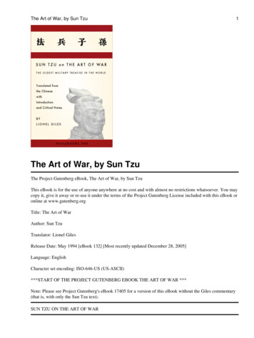
capability: the Bimodal Acoustic (BAT**) tool and the Pressure While Drilling(PWD) tool.Project BackgroundOil well logging is the process of acquiring data for formation evaluation(FE), the purpose of which is to determine the location of hydrocarbons in theformation, as well as to estimate the quantity in place. The primarymeasurements on which FE relies are the natural gamma ray, resistivity, neutronporosity, and bulk density. The gamma ray and resistivity measurements locateformations which are likely to contain hydrocarbons. The neutron and densitymeasurements are used to discriminate between oil and gas, as well as todetermine the volume of hydrocarbons in the formation. (Figure 1. Log Example )For most of the history of well logging, well logs were obtained after thewell was drilled. Tools were lowered into the well, and the measurements wereobtained as the tools were pulled from the hole by a wireline, which providedboth the power and the telemetry for the tools. During the 80s and 90s, tools formaking these measurements were designed into drill collars for logging whiledrilling (LWD). Sperry-Sun Drilling Services was a pioneering company in thisfield, introducing the first LWD neutron and density measurement tools, as wellas the first electromagnetic wave resistivity (EWR**) tool. The electromagneticwave technology evolved to become the most popular type of LWD resistivitymeasurement in the industry.While one goal of LWD is to replace wireline measurements, it also hasbecome an essential technology in other areas, providing measurements whichenable precision horizontal drilling and real-time information that can significantlyenhance drilling efficiency and well safety.LWD FE sensors, along with telemetry modules for communicating data tothe surface in real time, are b uilt into drill collars of various sizes to allow LWDthroughout a well. (Typically wells are begun with a larger diameter drilling bit,and smaller bits are used as the well depth increases.) Until recently, most LWDtools had a maximum operating temperature of around 150 C. This providedLWD capability in most of the reservoirs of interest in the world. However, deeperwells where gas is frequently found can exceed this temperature.To increase its presence in the HT market, in the 1990s Sperry-Sundeveloped the Solar 175 tool. This is a HT version of a Sperry-Sun system foreconomically making real-time directional and gamma ray measurements. Sinceborehole diameters in the deeper, higher temperature wells tend to be smaller,the Solar 175 tool was constructed in the smaller 4 ¾” diameter drill collar. Thissystem provided the starting point for the HT-LWD system of this project.**BAT and EWR are trademarks of Halliburton Energy Services, Inc.12
Project DE-AC26-97FT34175, “High Temperature LWD Project” waspartially funded by the U.S. Department of Energy in September 1997 withSperry Sun. After this project began, Dresser Industries, the parent company ofSperry-Sun, merged with Halliburton Company. Previous to the merger,Halliburton also had a sub-contract under Maurer Engineering. Maurer wascontracted with DOE to build a HT, real-time directional/gamma system,consisting of modules for communication, power, directional, and natural gammaray measurements. The technology and development departments of Halliburtonand Sperry Sun were integrated, and the Maurer/Halliburton DOE contract wascompleted, resulting in a system qualified to operate at 195 C. †† The knowledgegained in the Halliburton DOE contract contributed to the HT-LWD project.System DescriptionLWD systems are designed to acquire and record basic logging data whiledrilling and to transmit logging data to the surface using mud pulse telemetry.Well bore directional data transmitted to the surface are used to control the pathof the well bore to the target formation(s). Data from other LWD sensors are usedto evaluate these targets, to help make real-time drilling decisions, to detect wellproblems, and to provide “fine-tuning” to the well path (known in the industry as“geo-steering”).The HT-LWD system of this project combines modules from differentSperry-Sun systems. From the Solar 175 tool came the Telemetry Module (TM),Pulser/Generator, and the directional module (DM). From Sperry-Sun’s otherLWD systems come the gamma ray (DGR) tool, electromagnetic wave resistivity(EWR-P4) tool, compensated thermal neutron (CTN) tool, and stabilized lithodensity (SLD) tool.As noted above, HT sections of wells tend to be smaller diameter andtherefore the system specification called for capability in collars as small as 4 ¾”,for hole sizes in the 6” nominal range.The tool modules are housed in drill collars, which are thick walled drillpipe located immediately above the drilling bit. The Solar 175 modules are insondes which are installed in the central bore of the drill collars, while theremaining FE sensors are installed in annular inserts in the drill collars. In thecase of the resistivity and density tools, the inserts are connected electronicallyto sensors which are located in the periphery of the drill collar. Brief descriptionsof all these modules follow.††The final report for the project is ‘Development of a Mud-Pulse High-TemperatureMeasurement-While-Drilling (MWD) System”, January 2002, DE -AC26-97FT34345, MaurerTechnology Inc. and Sperry -Sun.13
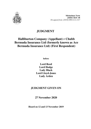
Pulser/Generator. Power for the system is generated in this module witha turbine driven by mud flow through the tool. The turbine also runs a hydraulicpump which operates a poppet valve that restricts the mud flow, creatingpressure pulses in the inner bore of the drill string. These pulses are the meansof transmitting the data to the surface. Bit rates are a few bits per second,approaching 10 bps in mild environmental conditions.Telemetry Module (TM). The telemetry module communicates with theother tools as well as with the pulser generator. The TM creates a transmissionsequence of the sensor data for the pulser ‡‡, controls the pulser operation, andconditions the power from the pulser/generator for use by the other modules.Data transmission with the pulser is possible only when the pumps are on andmud is flowing in the bore of the drill string. Other than sensing when pumps areon or off through the motion of the impeller in the pulser, communication betweenthe TM and the surface is one way. §§Directional Module (DM). This module contains three-dimensionalmagnetometer and accelerometer sensors. The data acquired are used tocalculate the direction of the well bore at each survey point (typically every thirtyfeet during drilling pauses for insertion of an additional “joint” of pipe in the drillstring). On the surface, this information can be used to guide the well to apredetermined target chosen by some other means, usually a seismic survey.Battery Module (BM). Mud flow and the power generated from it are notcontinuous during the drilling operation, so a battery module is necessary tomaintain operation of the electronics during drilling pauses. It is during the drillingpauses, for example, that the most accurate directional information is acquired.BM battery cells are available in several temperature capability ranges, up to180C.Electromagnetic Wave Resistivity Phase 4 / Dual Gamma Ray(EWRP4-DGR). The natural gamma ray and resistivity modules are locatedtogether in one drill collar. The most basic function of the gamma raymeasurement is to discriminate between porous rocks which may containhydrocarbons (sandstones, limestones) and rocks which do not (shales). Themeasurement is a count of gamma rays from the inherent radioactivity of theformation and exploits the fact that shales are usually more radioactive thansandstones o r limestones. In this project, the gamma rays are detected by‡‡The TM transmission scheme initially used Manchester encoding, where data arephase encoded into a regular clock cycle. A “1” or a “0” is encoded in the middle of each clockcycle, where a “1” corresponds to a rise in pressure, and a “0” to a fall in pressure. Oneimprovement of this project was to change the encoding scheme to the more efficient pulseposition modulation method (see below).§§Greater bandwidth “downlink” technology is available in the form of Sperry’sGeoSpan technology, which can transmit complex commands from the surface to downhole.Instead of the TM, this system requires the CIM and PWD modules (see below) downhole.14
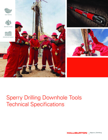
Geiger-Mueller (GM) tubes. The tool is referred to as a “dual” measurementbecause the tubes are arranged in two independent but otherwise redundantbanks. An individual tube is a gas-filled cylinder with a wire running along itscentral axis. Gamma rays passing through the tube create a detection eventwhen they produce electron-ion pairs in the gas or inner wall of the cylinder. Thetubes operate with an electric potential between the wire anode and the tube wallthat is sufficient to initiate a n avalanche of charge to the anode. The resultingelectrical pulse on the anode is registered in the counting electronics. Othertechnologies, such as sodium iodide scintillation detectors, are more efficientgamma ray detectors; however, GM tubes perform adequately at temperatureswell above those at which scintillation systems seriously degrade or cease tofunction.The resistivity measurement (EWRP4) is used to discriminate conductiveporous formations containing brine from those resistive formations containinghydrocarbons; it is also used to infer the relative fractions of hydrocarbons andbrines in a formation when both are present. Resistivity is determined from thedifference in phase at two receiving antennas of an electromagnetic wavetransmitted through the formation. Four different phase measurements areacquired, using four transmitters located at different spacings from the receiverpair. The sensitivity to the formation away from the borehole increases withincreasing transmitting antenna spacing . The resistivity of the fluid in theborehole is usually different from that of the formation, with a transition – orinvasion – zone between them. The four different measured values of resistivitycan be combined in computer models to compute values for the resistivity of theborehole, the invaded zone, and the formation.Compensated Thermal Neutron (CTN). The neutron measurement is ameans of determining the porosity of the formation containing brine orhydrocarbons. The total volume of hydrocarbons in place may be estimated oncethe porosity is known.The neutron measurement exploits the fact that high energy neutronsemitted into the formation are slowed through collisions with atoms in theformation. Because the hydrogen nucleus has nearly the same mass as theneutron, it is the most efficient element i n slowing neutrons to thermal energies.In porous rocks, hydrogen is usually present only in the water or thehydrocarbons occupying the rock pore space. Thus, a measurement of thethermal neutron concentration around the neutron tool can be used to computethe amount of hydrogen in the formation and, in turn, the porosity of theformation.The tool employs a source of high energy ( MeV) neutrons and twodetectors which are sensitive to neutrons at thermal energies ( 1eV). Theneutron detectors are proportional counters filled with helium-3 gas. In adetection event, a thermal neutron combines with a helium-3 nucleus in an15
exothermic reaction releasing a precise and repeatable amount of energy thationizes the gas in the tube. The subsequent proportional action of the tuberesults in an electrical pulse of repeatable amplitude. This reproducibility allowsneutron events to be distinguished from other, usually lower amplitude, eventscaused by other ionizing radiation such as gamma rays.Porosity is computed from the ratio of the response of the two differentlyspaced detectors. Certain environmental effects, such as borehole and formationsalinity, can be proportional in both detectors. Their effect is therefore reduced inthe ratio of the detector responses. The conversion to porosity is accomplishedby applying a succession of corrections which deal with the effects of holediameter, formation fluid density and salinity, formation salinity, tool positionwithin the borehole, and formation type – factors the values of which may eitherbe assumed or determined from other measurements.Stabilized LithoDensity (SLD). The SLD tool is Sperry-Sun’s version ofthe gamma-gamma density measurement tool which is used throughout thewireline and LWD industries. Gamma rays emitted by a radioactive source,usually cesium-137, scatter from electrons into the borehole and formation,losing energy as they scatter. They are registered by two detectors differentlyspaced from the gamma source. The primary mechanism for interaction of higherenergy gamma rays with the formation is scattering from electrons, theconcentration of which is proportional to the formation bulk density. The numberof lower energy gamma rays is also affected by photoelectric absorption, which isa function of the chemical constitution of the formation. The density of theformation is inferred from the number of higher energy backscattered gammarays detected. By comparing the number of high and low energy gamma rays,information about the mineralogy may be obtained as well.The detectors consist of sodium iodide scintillators paired withphotomultiplier tubes (PMT). Gamma rays interact with electrons in the sodiumiodide crystal to produce scintillations, which are in turn converted to electricalpulses by the PMT. The pulse amplitudes, which are proportional to the gammaray energy producing the scintillations, are digitized and stored by theelectronics. This provides an energy discrimination capability which enables thetool to provide a measure of both the formation density, as well as an indicationof the formation mineralogy (e.g., limestone, sandstone, or dolomite).Of the FE tools discussed above, the density tool senses the smallestvolume of formation in the process of making its measurement. This property isexploited in some tools by acquiring data “azimuthally” – that is, combiningdensity measurements with simultaneous determination of the orientation of thetool in the borehole. Since the tool is usually rotating within the hole, this allows a360 density “image” of the formation near the borehole to be constructed. Suchimages are useful in well bores where the formation density is non-uniformaround the well bore, either because of formation heterogeneity, or because the16
well bore is crossing a boundary between different formation layers. The lattercase is important i n geosteering applications where precise placement of the wellbore within the formation is required. This imaging capability is part of the mostadvanced Sperry-Sun density tools, and o ne of the final tasks in this project wasto add it to the HT-SLD tool.Central Interface Module (CIM). The CIM, also an insert-based module,performs all functions of the TM, but provides other capabilities as well. It hasmemory sufficient to store all tool logging data (the TM stores only transmitteddata). It has a high speed download capability, and manages all sensors in theSperry-Sun fleet. In contrast to the TM, the CIM software can easilyaccommodate additional new sensors as they are developed. A HT version of theCIM is therefore the obvious next step in expanding the HT-LWD capability.Although it was not included in the DOE project for HT-LWD, Sperry-Sun hasinitiated a self-funded program to develop the HT-CIM.Other Sensors. There are other sensors in the Sperry-Sun fleet, notspecified as part of this project, which provide measurements that can beimportant to drilling safety and to the evaluation of deeper, HT wells. ThePressure While Drilling (PWD) tool measures the fluid pressure in the bore of thedrill string and in the annulus between the drill string and the borehole wall. Realtime measurement of pressure can be of particular importance in the moredifficult drilling situations and is useful in optimizing drilling practice and rigsafety.Sperry-Sun’s Bimodal Acoustic (BAT) tool measures direct and shearacoustic velocities of the formation. These parameters are useful in FE as well asin drilling optimization. The principal elements of the tool are a pair ofdiametrically opposed acoustic transmitters mounted in the drill collar, and anarray of seven transducer-receiver pairs, also diametrically mounted. Thecoherency of the waveforms arriving at the seven receivers allows extraction ofthe various acoustic velocities of the formation (e.g., compressional and shear).The PWD and BAT tools have been upgraded to HT (i.e., 175 C) or near HTstatus and can be deployed in a HT system when the HT-CIM is used.17
Project Tasks and AccomplishmentsThe major tasks and accomplishments of this project will be discussed inthis section. The testing and integration procedures that Sperry-Sun uses toinsure reliable operation of its tools for extended periods in hostile operatingconditions will be outlined as well. Halliburton and Sperry-Sun have a number ofenvironmental and mechanical testing facilities for qualifying and troubleshootingLWD tools. These are outlined briefly in the following table:VibrationPressureFlow LoopsTemperatureFatigueMechanicalTesting LaboratorySensor calibrationDrilling simulatorHalliburton Testing FacilitiesMultiple tables, exceeding 25g RMS, 3-axis mounting ,simultaneous 200 C.Random shocks of several Kg’sSix pressure vessels, 35 Kpsi, 250 C (Max volume 12”(Diam) X 27’)Several loops up to 6000 ft in length. Two triplex pumps, upto 1400 gal/min.Numerous ovens for testing/cycling components, boards,inserts, and assembled tools.Full scale rotary/bending machine for drill collar testingVariety of metallurgical testing capabilities -- hardness,stress/strain, corrosion, & chemical testing.Microscopic, X-ray, SEM analysis.Facilities for testing, calibration, and characterization ofnuclear and electromagnetic tools .Resistivity tools – water tanks and air hang facilities for toolcharacterization and calibration.Nuclear tools – Tool Response and CharacterizationLaboratory (TRAC Lab), with 3 dozen formationsand 50 borehole sizes for response measurement ofneutron, density and natural gamma ray tools.Test wells and formations for testing tool & systemoperations under simulated drilling conditions.Oven facilities for testing operating nuclear tool attemperature.Facility for testing downhole tools by drilling up to a 60’ holein a concrete formation; includes triplex pumps andtop drive with up to 120 Klb weight on bit.18
Testing Procedures and Processes. Sperry-Sun’s electronic boarddevelopment process includes qualification and integration testing at appropriatestages of assembly. Individual boards are functionally tested both on the benchand with “shake and bake” procedures – that is, operating while under vibrationand HT simultaneously. The final qualification test for a board consists ofsuccessful, continuous operation at 175 C for more than 1000 hours. Integrationtesting continues on board sets as well as on complete assemblies, includingassembled tool strings.As indicated earlier, PC boards containing the electronics for the FEsensors are mounted on annular inserts which fit into bored out drill collars. Theboards and inserts are installed in the drill collars at atmospheric pressure, andradial o-ring seals are used to secure the insert environment against downholepressures.For this project, the o -ring material was changed to a substance morestable against higher temperatures, and the o-ring design was mo
Sperry-Sun Drilling Services understands that DOE's objective is to increase the available gas resources and to assist industry in meeting natural gas production requirements of the nation. Significant deposits of this resource are believed to be in deep, HT gas prospects such as the deep Austin Chalk and Western Gulf of Mexico. Accordingly, the.