Transcription
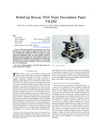
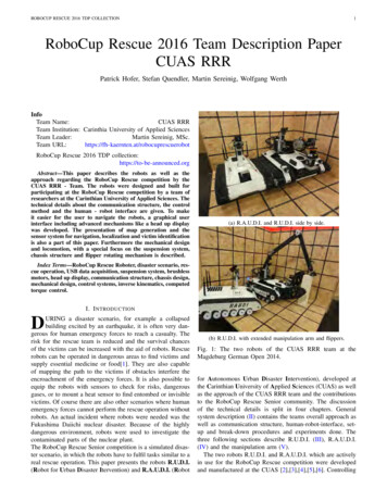
ROBOCUP RESCUE 2016 TDP COLLECTION1RoboCup Rescue 2016 Team Description PaperCUAS RRRPatrick Hofer, Stefan Quendler, Martin Sereinig, Wolfgang WerthInfoTeamTeamTeamTeamName:CUAS RRRInstitution: Carinthia University of Applied SciencesLeader:Martin Sereinig, oboCup Rescue 2016 TDP his paper describes the robots as well as theapproach regarding the RoboCup Rescue competition by theCUAS RRR - Team. The robots were designed and built forparticipating at the RoboCup Rescue competition by a team ofresearchers at the Carinthian University of Applied Sciences. Thetechnical details about the communication structure, the controlmethod and the human - robot interface are given. To makeit easier for the user to navigate the robots, a graphical userinterface including advanced mechanisms like a head up displaywas developed. The presentation of map generation and thesensor system for navigation, localization and victim identificationis also a part of this paper. Furthermore the mechanical designand locomotion, with a special focus on the suspension system,chassis structure and flipper rotating mechanism is described.(a) R.A.U.D.I. and R.U.D.I. side by side.Index Terms—RoboCup Rescue Roboter, disaster scenario, rescue operation, USB data acquisition, suspension system, brushlessmotors, head up display, communication structure, chassis design,mechanical design, control systems, inverse kinematics, computedtorque control.DI. I NTRODUCTIONURING a disaster scenario, for example a collapsedbuilding excited by an earthquake, it is often very dangerous for human emergency forces to reach a casualty. Therisk for the rescue team is reduced and the survival chancesof the victims can be increased with the aid of robots. Rescuerobots can be operated in dangerous areas to find victims andsupply essential medicine or food[1]. They are also capableof mapping the path to the victims if obstacles interfere theencroachment of the emergency forces. It is also possible toequip the robots with sensors to check for risks, dangerousgases, or to mount a heat sensor to find entombed or invisiblevictims. Of course there are also other scenarios where humanemergency forces cannot perform the rescue operation withoutrobots. An actual incident where robots were needed was theFukushima Daiichi nuclear disaster. Because of the highlydangerous environment, robots were used to investigate thecontaminated parts of the nuclear plant.The RoboCup Rescue Senior competition is a simulated disaster scenario, in which the robots have to fulfil tasks similar to areal rescue operation. This paper presents the robots R.U.D.I.(Robot for Urban Disaster Itervention) and R.A.U.D.I. (Robot(b) R.U.D.I. with extended manipulation arm and flippers.Fig. 1: The two robots of the CUAS RRR team at theMagdeburg German Open 2014.for Autonomous Urban Disaster Intervention), developed atthe Carinthian University of Applied Sciences (CUAS) as wellas the approach of the CUAS RRR team and the contributionsto the RoboCup Rescue Senior community. The discussionof the technical details is split in four chapters. Generalsystem description (II) contains the teams overall approach aswell as communication structure, human-robot-interface, setup and break-down procedures and experiments done. Thethree following sections describe R.U.D.I. (III), R.A.U.D.I.(IV) and the manipulation arm (V).The two robots R.U.D.I. and R.A.U.D.I. which are activelyin use for the RoboCup Rescue competition were developedand manufactured at the CUAS [2],[3],[4],[5],[6]. Controlling
ROBOCUP RESCUE 2016 TDP COLLECTIONthe robots is accomplished with the help of four subsystems,two windows based systems for R.U.D.I. and two Linux basedsystems for R.A.U.D.I.[7],[8],[9].A. Improvements over Previous ContributionsThe first participation of the team at the RoboCup was at theRoboCup German Open in year 2013[10]. There the team ofthe CUAS started with the remote controlled Robot R.U.D.I.and accomplished the third place. At the RoboCup GermanOpen in 2014 the team participated with two robots. Therethe robot R.U.D.I. and the new developed autonomous robotR.A.U.D.I. where used in cooperation. The robot R.U.D.I. wasequipped with a new manipulation arm. With this setup theteam was able to achieve the third place again. In 2015 theresearchers developed a new control strategy, including a newcontrol algorithm[11] and an inverse kinematics algorithm[12]for the manipulation arm. The current work will focus onthe collaboration between the two robots. This will improvethe performance at the proposed participation at the RoboCupWorldCup in 2016.II. G ENERAL S YSTEM D ESCRIPTIONThe team of researchers at the CUAS developed two different robot platforms. The remote controlled robot R.U.D.I.was designed to drive to rough terrain and overcome higherobstacles, the second robot R.A.U.D.I. was designed to workautonomously. During a mission both robots should worksimultaneous in the area to increase efficiency. The followingsections describes the basic features for both developed robots,whereby the multi operating system approach, where Windowsand Linux is used in combination to control the robots, ispointed out.A. CommunicationThe communication between the operator station and therobots is done throughout the WNDR3700 router from Netgear. It acts as a platform for remote controlled, partiallyautonomous and fully autonomous actions of the robots. Italso supports true dual bands, offering simultaneous WirelessN performance in both 2.4GHz and 5GHz bands. The 5GHzband is preferred basically, because of the low distribution andsubsequently less utilized communication channels.At software level the exchange of information is splitinto the Winsock-API and the ROS internal communicationstrategy. The data packets are transferred from the Operatorstation to the robots and vice versa, whereby both kind ofsockets, TCP and UDP are used to establish connectionsin a convenient way. If it comes to videostreaming thetransmission of faulty data packets or even a loss of datamay be acceptable, so transmission via UDP was taken intoconsideration. On the other hand, if it comes to a transmissionof control data, a secure and failure free connection should beguaranteed, which leads to the use of the more reliable TCPprotocol. Connected to this increased transmission latenciesand in average slower data throughput must be taken intoaccount.2TABLE I: Communication dataRescue Robot LeagueCUAS RRR-Team (AUSTRIA)FrequencyChannel/Band Power (mW)2.4GHz - 802.11n111005GHz - 802.11n48(TPC)200The communication between both robots was establishedby using ROS standards. Therefore ROS was installed on theWindows7 OS which is used on R.U.D.I. and on the robotremote system.B. Human-Robot InterfaceThe interaction between operator and robot is achievedthroughout the use of a multifunctional joystick. Further thejoystick is coupled with the robot remote system (RRS)respectively a HP Elitebook laptop which is connected tothe robots control system via WLAN. As part of the RRS, agraphical user interface provides all necessary informations ofthe robots current condition to the operator. These are e.g. livecamera view for navigation but also basic status informationlike orientation of the robot in the plane.1) Input Device: The input device is represented by aThrustmaster Hotas Warthog joystick. On one hand it possesses multiple rotational and linear axis and on the otherhand various buttons make the device a powerful functionaluser input platform. Interfacing with the joystick is done viaUSB and further on DirectX is used for a windows basedapplication development.2) Graphical User Interface: For both robots a graphicaluser interface (GUI) was developed where all useful information for the operator is shown. The GUI for R.U.D.I. is aC# based application running on a Windows platform, whichis shown in figure 2. The GUI for R.A.U.D.I., a C basedapplication running on a Linux platform, can be seen in figure3. Both GUIs contain the following informations: List of basic sensordata (e.g. power supply status, orientation of the robot in the plane, status of motor controllerboards, etc.) Live camera stream of the robot for navigation 3D-View of the robot inside the arena Current status/overview of acquired 2D-mapping Menu structure for triggering shortcuts and administrativetasksIt is difficult to filter and display the data, which is receivedfrom the robot, in a convenient way. Therefore, in additionto the foregrounded interface, where important information isshown only, a back-end with all collected data is implemented.So the operator is able to concentrate on the most importantinformation while controlling the robot in a conventional way.On the other hand if failures occur it is possible to investigateon the saved data where detailed status information of therobot can be extracted.For the remote controlled robot a head up display (HUD)as shown in figure 4 makes important data available at firstsight. Based on concepts which are widely used in aircrafts,like jet fighters, the following content has been implemented:
ROBOCUP RESCUE 2016 TDP COLLECTION3Fig. 2: Overview of the current graphical interface used forR.U.D.I.Fig. 4: Overview of the HUD.Fig. 3: Overview of the current graphical interface used forR.A.U.D.I.Horizon (A): The horizon basically represents the currentoffset nick-angle from the zero-level. This offset is updated in real time and scaled by horizontal lines whichare drawn over constant intervals. Throughout this, thehorizon is able to provide the operator with importantorientation information while climbing up or movingdown stairs or getting over some obstacles. Providinginformation about roll- and pitch-angle are taken intoconsideration. Flipper-position (B): Another important type of information, which has to be reachable as fast as possible,is the position of the flipper arms. It is represented byelliptic trajectories, whereby a vector points to the currentposition.It is noticeable that the elements which are used inside of theHUD, may seem simple at first sight. On the other hand especially this circumstance contains a lot of capabilities, becausethe designer is forced to accommodate information in a simpleway, concurrently concentrating on most important elementsonly. For example, by the use of just two more mechanisms(besides of the form), color and thickness may extend theprospects of information-representation by a multiple. C. Set-up and Break-DownThe operator station consist out of a steel constructionequipped with wheels for a easy transport. This construction isadjustable for different operators and different environmentalconditions. Furthermore it offers enough space for the remoterobot control unit, the router and the grid independent powersupply. The remote robot control unit of the rescue robot consists of two HP Elite notebook where the remote applicationsincluding the graphic user interfaces are running. Beside thismode of operation an additional input device, the joystick, isneeded. The entire remote control unit is portable and can beset up by a single person.The robots itself can be transported in a box armed withwheels. The start-up sequence is simple and the robots areready to use in about ten minutes after it is placed at theoperation area. The connection between robots and remotesystems is established automatically.D. ExperimentsAt the CUAS a special test laboratory was implementedwhere different testing areas can be used according to theRoboCup Rescue rules. Furthermore tests under differentenvironmental conditions (indoor and outdoor) were made.Therefor the robots were tested on a scrap yard, under urbanconditions and in the forest as shown in figure 5 and figure 6.III. S YSTEM D ESCRIPTION : R.U.D.I.R.U.D.I. is a tracked mobile robot, equipped with a mountedmanipulation arm as given in figure 1. The representation ofthe robot in figure 8 helps to discuss the robots subsystems andtheir position within the chassis. The main drive of the robotconsists of two 200W brushless DC electric motors whichpowers a track (A) with rubber pads. This track is suspendedby a spring-damping element to increase overall mobility anddrive performance. The battery storage (B) contains lithiumpolymer batteries. Two cell packs, ten cells each, provide theenergy for locomotion and manipulation of the arm drives,while two separate packs (6S-packs) power the computationalunit. With the help of the gearbox (C) two flipper arms (D)can be rotated independently by 360 . Flipper arms are used
ROBOCUP RESCUE 2016 TDP COLLECTION4Fig. 5: R.U.D.I. tested on a scrap yardFig. 7: Top view of R.U.D.I.s partly-assembled frame andgearbox.suspension system. The frame construction together with sixelectric drives and the flipper gearbox is given in figure 7.Steel sheet metal parts can be manufactured using laser-Fig. 6: R.A.U.D.I. tested under urban conditionsto overcome obstacles like steps and can be driven standalone from the main drive. The main computing elementis an Intel i5 processor mounted on a Mini-ITX mainboardlocated below the louver (E). On-Off switches and the killswitch are mounted on a operating panel. The on-off switchesare only accessible when the cover panel (F) is lifted. Amodifiable cover (G) allows the clean mounting of additionalsystems. Although R.U.D.I. is designed especially for theRoboCup Rescue Senior competition, where a manipulationarm is essential, the robot can be used as a carrier platformfor diverse systems.A. Mechanical DesignR.U.D.I.s chassis is composed of a frame, manufacturedusing engineering plastics, and steel sheet metal parts. TheTECAMID6 GF30 plastic is reinforced with 30% glass fibre.The parts where designed using the software Solid Edge andproduced with CNC machines. Therefore they represent aconvenient and precisely manufactured foundation for morecomplex systems like the flipper gearbox and main driveFig. 8: System Description of R.U.D.I.cutting technology and formed using sheet metal bendingmachines. Some work-pieces are welded together to augmentrigidity of the overall design. They are mounted to the plasticframe using screws, in order to increase stiffness of the robotschassis. Hence the sheet metal parts can be disassembled fromthe frame, access for maintenance can be reestablished quickly.Another core feature of R.U.D.I. is the suspension system,composed of six ground roller groups per main drive, oneof these groups is explicitly seen in figure 9. Two groundrollers (A) are connected with an axis (E) and hold in placewith circlips (D). Roller bearings are fixated in the mountingplate (I) with bearing cups (B), axial fixation of the shaft(H) is also realised with circlips (C). A mechanical stop(G) limits the rotational freedom of the connection rod (F).Using another connection rod (N) the mounting of the springdamping element (M) is realised. A slide bearing (K) holds the
ROBOCUP RESCUE 2016 TDP COLLECTIONJ5KILHfixated with thumb screws to the chassis. The main computingunit is a Mini-ITX mainboard with Intel i7 processor. Thebattery pack consists of four separate lithium-polymer cellpacks providing energy supply for computing unit and drive.MGNFEDCBAFig. 9: Sectional view of a single suspension element.upper mounting point (L) of the element. R.U.D.I.s suspensionsystem allows a smother ride compared with purchasablemobile robot systems of similar size. The spring-dampingelements are inside of the robot, isolated from dirt andmoisture by the mounting plate (I).Surface treatment of the steel sheet metal parts, the aluminiumparts and the steel flipper gearbox shafts is realised withpowder-coating, anodic treatment and black-oxide finishing[3], [5].B. Software DesignControlling R.U.D.I. is accomplished with the help oftwo large subsystems. The robot remote system (RRS) andthe robot control system (RCS). Noticeable about RCS isthe operating system, here Windows 7 Professional is used.Furthermore the RCS interfaces with USB based hardwaremodules from the company Phidgets [13], [7].1) Robot Remote System: The RRS is used on the operatingstations laptop to compute input commands from the operatorand display informations provided for the operator. Controlcommands are transferred cyclic to R.U.D.I. via WLAN. Errormessage and safety related mechanisms are also included.2) Robot Control System: The RCS is a soft realtimecontrol system for the mobile robot. A Mini-ITX mainboardwith an Intel i5 processor, SSD drive and 16GB Ram provideenough computational power to handle the high demand ofRoboCup Rescue tasks. A optimized Windows 7 with 64-bitarchitecture is the basic operating system, executing the C coded Win32- console application RCS [14].IV. S YSTEM D ESCRIPTION : R.A.U.D.I.R.A.U.D.I. is the second mobile robot platform developed atthe CUAS, again seen in figure 1. It presents an evolutionarystep which advances the teams capabilities in search andrescue operations. R.A.U.D.I. was designed as autonomousrobot, therefore it’s main application environment within thecompetition is the yellow arena. Track suspension technologyused for R.U.D.I. was developed further to improve ridequality in difficult terrain for R.A.U.D.I. The tracks aredriven by 200W brushless DC motors. Figure 10 shows therobot platform without metal sheet top covers and with openbattery storage cover. A HOKUYO UTM-30LX laser scanneris mounted on a levelling system and fixated to the batterystorage cover. In ready-for-operation configuration this clap isFig. 10: Rendering of R.A.U.D.I.s CAD model with openedbattery cover and removed sheet metal covers.A. Mechanical DesignR.A.U.D.I.s chassis structure is mainly composed of steelsheet metal parts which are screwed, welded and rivetedtogether. Engineering plastic parts are only used as baseplates to provide precise mounting points for the suspensionand drive-train-system, but are no primary load-bearing partswithin the frame structure. The self-restriction of only usingsteel sheet metal parts for the frame offers faster productioncycles and therefore lower manufacturing costs compared withthe compound chassis frame of R.U.D.I.R.A.U.D.I.s suspension system is a refined version ofR.U.D.I.s. Figure 11 shows six spring-damping element withground rollers. Compared with R.U.D.I.s suspension system,large diameter ground rollers are equipped, which implies alow-pass filter effect reducing the oscillations introduced bythe roller chain track. Spring-damping elements are outside ofthe robots chassis simplifying the mechanical structure of thesuspension system (compare with figure 9).An extension arm provides an elevated mounting point forimportant victim detection sensors like thermography- andvideo camera. The pan/tilt system is realized with DynamixelServos[15].B. Software DesignThe complete software of the autonomous robot is based onROS hydro for Ubuntu 12.04. As main control unit, a finitestate machine, written in C , is implemented. The flow-chartof the state machine is figured in 12. Based on the currentsensor readings, the state machine decides on the next task of
ROBOCUP RESCUE 2016 TDP COLLECTION6Fig. 11: Rendered side-view of R.A.U.D.I.s suspension systemwith dissembled side mounting plate and cover sheet.the robot. In the first state, the robot explores the unknownarea surrounding it. To localize itself in the environment andfor the mapping purpose, the Hector Slam algorithm has beenimplemented. As exploration algorithm, the Hector Navigationpackages are used[16]. After a set amount of time, the robotstops with the exploration and changes to the next state, whichis used to scan the surrounding area for possible victims. Ifa heat source is detected via the IR camera, the position ofthis source is computed and the robot changes to the approachstate. If nothing is detected during the scan, the robot continueswith the exploration. Once the previously detected heat sourceis reached, the robot starts with a further investigation ofthe supposed victim. Therefore, the different sensor readingsare checked for alternative victim criteria, like QR charts ormovement. If at least one additional criteria to the temperatureis detected by the robot, a signal is sent to the operatorstation, stating that a victim has been found. Once the operatoracknowledges the found victim, the robot starts again with theexploration process[9],[17].V. S YSTEM D ESCRIPTION : M ANIPULATION ARMMany different tasks in a catastrophic scenario require themanipulation or inspection of places which are difficult toreach for a mobile robot. To ensure the fulfilment of thosetasks a universal mountable manipulation arm was developed.Due to its flexibility different mobile robots can be equippedwith this robot manipulation arm with six degrees of freedom.The mechanical structure was keep light and small in order toachieve a low profile of the robot system. This ensures that thewhole mobile platform keeps its ability to operate all-terrainand also in low tunnels[18].A. Mechnical DesignThe arm itself consists of three main assembly groups asit can be seen in figure 13 . The base assembly group isvisualized by green color, the planar part of the arm by yellowand the end effector by blue. The base 1 is screwed to thechassis of the robot. To provide a rotary movement of theFig. 12: Flow-chart of the finite state machine used forR.A.U.D.I.manipulation arm the Brushless DC motor 3 moves the swivelplatform 2 . Three Harmonic Drive motors 5 provide themotion for the planar links of the manipulator arm 4 . Theend effector 6 is only drawn schematically.To ensure small dimensions in folded position on therobot and a large working area, a redundant kinematic chainstructure was chosen. The links were build of carbon fibreplastic to guarantee a lightweight construction. Due to thechosen rectangular profile the stability of the robot arm issufficient.B. Software DesignThe software needed for manipulation of the proposedarm can be divided into three different sections. These arethe main control algorithm design and the inverse kinematicalgorithm. The third part is related to the implementation ofthe developed algorithms on the robot. Figure 14 shows thebasic structure of the developed overall control strategy ofthe robot manipulation arm. The developed algorithms wheresimulated and tested using Matlab/Simulink.
ROBOCUP RESCUE 2016 TDP COLLECTION7dimensional space, relative to a coordinate system fixedon the end effector of the robot. The point of viewaligns with the joystick axis. If the orientation of theend-effector is changed, the view axis of the camera stillaligns with end effector and therefore the operator is ableto control the manipulation arm in a intuitive way.5Due to the redundant structure of the kinematic chain aclosed form solution is not applicable to solve the inversekinematic problem. Therefore a different approach using thecombination of optimization algorithms was used. Here iter3ative optimization methods like Newton-Raphson, BroydenFletcher-Goldfarb-Shanno and the Cyclic Coordinate Descent2algorithm by L.T.Wang and C.Chen were used [12]. The output1of the described algorithm, which was designed for solvinginverse kinematic problems, is used as input for the over allcontrol structure.Fig. 13: Schematic sketch of the manipulation arm2) Control Algorithm: To ensure the suitable motion inspace a cascaded control structure is used. The electric moAxestor of each joint is independently torque controlled by thejoyinputButtonsused motor controller modules[11]. Furthermore a ComputedTorque Controller (CTC), shown in figure 15, is used toprovide the reference torque for motor controller modules.This nonlinear control strategy enhance the robot manipulatorarm to have a good path following behaviour. In a CTC, theFig. 14: Flow chart of the control strategyinertia M , the centrifugal C and the gravitation G dependingmatrices have to be calculated. Therefore the physical properties of the robot manipulation arm has to be known very1) Inverse Kinematics: To ensure a fast and easy usable well. The inner loop of the CTC is used to fully linearise themovement of the robot arm in space a inverse kinematics system, the outer loop includes a control law which defines aalgorithm was developed[12]. The main challenge of inverse needed behaviour of the overall system [11].kinematics is to calculate the joint variables with a givendesired position and orientation of the end-effector.Robot modelThere are three reasonable ways to describe the desiredTCR q̇ R qq̈des1 q̈Mestposition and orientation with the help of a joystick input:M The input is a point in the three - dimensional space,N Grelative to a coordinate system fixed on the robot base.This method is often chosen for industrial manipulators.The fixed global coordinate system allows the operator toNest Gestposition the end effector in exact locations with certainCoutorientation. However, there are problems when using thismethod for a mobile robot. Firstly, when operating thearm in a rescue scenario the end-effector goal position is Fig. 15: Schematic drawing of the Computed Torque Controlnot known beforehand, but has to be converged slowly loop.by hand to avoid obstacles and keep the victims safe.3) Software Implementation: The mentioned algorithmsSecondly, the operators video steam is provided by awereimplemented as C-functions generated by the Matcamera mounted on the end effector of the manipulationlab/Simulink-Code generator. The developed RCS on R.U.D.I.arm. Therefore the operator does not have a visualprovidesthepossibility to include those generated functions.information about the position in the global coordinateFurthermoreROSnodes were implemented to insure compatsystem.ibilitywithmobilerobot platforms using ROS. The input is a relative movement of a point in the three dimensional space, relative to a coordinate system fixedA PPENDIX Aon the robot. Hence the input is a speed the usage ofTEAMMEMBERSAND T HEIR C ONTRIBUTIONSthe Joystick is intuitive. However, there is a problemwhen the orientation of the end-effector is changed. TheThe RoboCup Rescue Robot R.U.D.I. was designed andpoint of view no longer aligns with the axis mapping developed by the first team between summer 2011 and summeron the joystick and therefore the operator is unnecessary 2012. The team in 2013 was responsible for the buildingchallenged.process and the first test drives of the robot. Furthermore The input is a relative movement of a point in the three a manipulation arm was developed by a subgroup of the64Position and joint angle changeJoystick input by userJoint angleTorqueActual position as initioal conditionInverse KinematicAlgorithmusTorqueJoint angle sensorReal SystemGUIComputed Torque ReglerJoint anglesTorqueActual joint angles
ROBOCUP RESCUE 2016 TDP COLLECTION8TABLE II: Robot for Urban Disaster ackedSystem Weight55kgWeight including transportation case60kgTransportation size0.6 x 0.62 x 0.5 mTypical operation size0.6 x 0.62 x 0.5 mUnpack and assembly time10 minStartup time (off to full operation)10 minPower consumption (idle/ typical/ max)120 / 300 / 540 WBattery endurance (idle/ normal/ heavy load)60 / 40 / 25 minMaximum speed1 m/sPayload15 kgAny other interesting attributetwo additional drives (flippers)Cost25000 EuroTABLE III: Robot for Autonomous Urban Disaster trackedSystem Weight25kgWeight including transportation case30kgTransportation size0.6 x 0.4 x 0.45 mTypical operation size0.6 x 0.4 x 0.45 mUnpack and assembly time10 minStartup time (off to full operation)10 minPower consumption (idle/ typical/ max)120/ 300 / 450 WBattery endurance (idle/ normal/ heavy load)60 / 40 / 30 minMaximum speed1 m/sPayload1kgAny other interesting attribute3 DOF sensor headCost10000 Euroteam members in spring 2013. In 2014 the new controlstrategy, including the inverse kinematics and overall controlleralgorithm, were developed. From 2015 up to now all robotswere tested and optimised by the core team.A. Core Team Wolfgang Werth, Supervisor, since 2011Stefan Quendler, Mechanical design and control systems,since 2011Martin Sereinig, Actuator and control systems, since 2011Patrick Hofer, Software and electronics design, since2012TABLE IV: Robot manipulation armAttributeValueNameCuas Robot ArmLocomotionJoint actuatorsSystem Weight12kgWeight including transportation case15kgTransportation size0.7 x 0.2 x 0.2 mUnpack and assembly time10 minStartup time (off to full operation)10 minPower consumption (idle/ typical/ max) 20 / 100 / 300 WPayload (typical, maximum)0.2/ 1 kgArm: maximum operation height150 cmCost9000 EuroTABLE V: Operator StationAttributeValueSystem Weight20kgTransportation size1 x1 x 0.5 mTypical operation size1.5 x 1.5 x 1.5mUnpack and assembly time10 minCost300 EuroTABLE VI: Hardware Components ListPartBrand & ModelMain drive motorsEC-4pole Motor 30 BL 200WFlipper rotation motorsEC-max 40 BL 70WFlipper drive motorsEC-max 40 Flat 70WMotor robot armFHA 17 CMotor robot armFHA 14 CMotor robot armFHA 11 CGearsPlanetary Gearhead GP 42CEncoderEncoder HEDS 5540Motor driversESCON 70/10Motor drivers flipperDEC Module 50/5Motor driver robot armESCON Module 50/5BatteriesLippo AkkuMicro controllerArduino UnoDAQ Modules1018 PhidgetInterfaceKit 8/8/8Computing UnitMini ITX PCIMUPhidgets IMUCamerasFL3-U3-88S2C-CInfrared CameraOptris PI 160Temperatur Sensor1045 PhidgetTemperatureSensor IRLaser RangefinderUTM-30LXOperator Laptop 1hp elitebook 8760 wOperator Laptop 2hp probook 650 g1Unit Price Num.600 Euro4425 Euro2300 Euro22500 Euro11700 Euro21600 Euro12008806250 Euro460 Euro4110 Euro61001035 Euro170 Euro1500 Euro2120 Euro21250 Euro22500 Euro160 Euro14500 Euro12000 Euro11500 Euro1A PPENDIX BL ISTSA. Systems ListThis section shows the propertie
RoboCup Rescue 2016 TDP collection: https://to-be-announced.org Abstract—This paper describes the robots as well as the approach regarding the RoboCup Rescue competition by the CUAS RRR - Team. The robots were designed and built for participating at the RoboCup Rescue competition by a team of researchers at the Carinthian University of .