Transcription
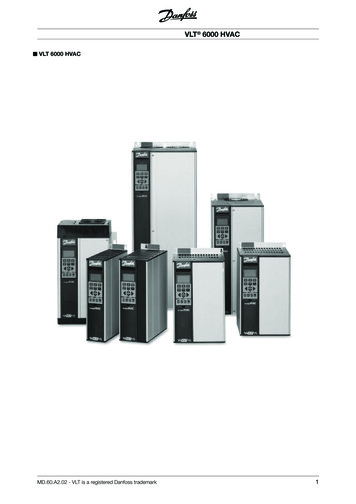
MAKING MODERN LIVING POSSIBLEOperating InstructionsPositioning Controller MCO 351VLT AutomationDrive FC 301/302www.danfoss.com/drives
ContentsOperating InstructionsContents1 Introduction41.1 Purpose of the Manual41.2 Additional Resources41.3 Overview41.3.1 Software Version1.4 Approvals51.5 Disposal52 Safety62.1 Safety Symbols62.2 Safety Warnings62.3 Functional Safety73 Mechanical Installation84 Electrical Installation104.1 MCO 350/351 Control Terminals104.1.1 Enclosure Types A2 and A3104.1.2 Enclosure Types A5, B1, and B2104.2 Frequency Converter Control Card Terminals114.3 Wiring Diagram134.4 MCO Option Card Terminals144.4.1 X55 Feedback Encoder Input144.4.2 X56 Master Encoder Input/Virtual Master Output144.4.3 X57 Digital Input144.4.4 X58 24 V DC Supply154.4.5 X59 Digital Outputs154.4.6 X62 MCO-CAN154.5 Description of Terminals164.5.1 Frequency Converter Control Card Terminals164.5.2 MCO Digital Inputs Terminal (X57)174.5.3 MCO Digital Outputs Terminal (X59)174.5.4 MCO Encoder Connection184.5.4.1 Encoder Connection Examples184.6 Fieldbus Interface204.6.1 Introduction204.6.2 Data Layout205 Commissioning235.1 Safety InstructionsMG33R302423Danfoss A/S 04/2014 All rights reserved.1
ContentsOperating Instructions5.2 Basic Parameters Set-up235.3 Basic Set-up235.4 PID Settings235.5 Description of Application Parameters245.5.1 19-** Application Parameters5.6 MCO Basic Settings295.6.1 32-0* and 32-1*, Encoder 2 Parameters295.6.2 32-3* and 32-4*, Encoder 1 Parameters315.6.3 32-5* Feedback Source335.6.4 32-6* and 32-7*, PID-Controller Parameters345.6.5 32-8* Velocity & Acceleration365.7 MCO Advanced Settings385.7.1 33-0* Home Motion385.7.2 33-4* Limit Handling385.7.3 33-8*, Global Parameters405.7.4 33-9*, MCO Port Settings405.8 MCO Data Readouts415.8.1 34-0*, PCD Write Parameters415.8.2 34-2*, PCD Read Parameters415.8.3 34-4*, Inputs and Outputs415.8.4 34-5*, Process Data416 Application Examples426.1 Homing426.2 Touch Probe Positioning426.3 Brake Control426.4 Hardware End Limit436.5 Software Limits436.6 Index Positioning436.7 Quick Bus Positioning447 Diagnostics457.1 Troubleshooting457.2 Error Messages468 Appendix224488.1 Abbreviations and Conventions488.2 Glossary of Key Terms488.3 Positioning508.3.1 Positioning Table508.3.2 Positioning Templates51Danfoss A/S 04/2014 All rights reserved.MG33R302
ContentsOperating Instructions8.3.2.1 Example of Index Positioning via Fieldbus518.3.2.2 Example of Index Positioning via Quick Bus51IndexMG33R30252Danfoss A/S 04/2014 All rights reserved.3
1 1IntroductionOperating Instructions1 Introduction1.1 Purpose of the Manual1.3 OverviewThese Operating Instructions provide information for safeinstallation and commissioning of the VLT PositioningController MCO 351. The Operating Instructions areintended for use by qualified personnel. Read and followthe Operating Instructions to use the product safely andprofessionally, and pay particular attention to the safetyinstructions and general warnings. Keep these OperatingInstructions available with the MCO 351 at all times.The VLT Positioning Controller MCO 351 is for use withthe FC 300 series frequency converters. The control cardoption expands the functional properties of the frequencyconverter in positioning applications. It is user-friendly,enabling the set-up of all parameters via the VLT AutomationDrive Local Control Panel (LCP) or via the VLT MCT 10 Set-up Software.Compliance with the information in these OperatingInstructions is a prerequisite for: Trouble-free operationRecognition of product liability claimsTherefore, read the Operating Instructions before workingwith the MCO 351.VLT is a registered trademark.1.2 Additional ResourcesResources available to understand advanced frequencyconverter and MCO functions and programming: VLT AutomationDrive FC 301/FC 302 OperatingInstructions VLT AutomationDrive FC 301/FC 302 DesignGuide VLT AutomationDrive FC 301/FC 302Programming Guide Motion Control Option MCO 305 OperatingInstructions Motion Control Option MCO 305 Design GuideSupplementary publications and manuals are availablefrom Danfoss. See mentations/VLT Technical Documentation.htmfor listings.4The module is available as an option card for field installation or as a built-in option in all VLT AutomationDrives.It is available with and without conformal coating.As the MCO 351 is a standard product with fixedfunctional properties, no additional applicationprogramming is required.The positioning controller can handle most positioningapplications with vertical as well as horizontal movements.The option is suited for applications with an overall controlsystem, for example a PLC.The main features are: Direct positioning via fieldbusRelative, absolute, and touch probe positioning32 fixed positions (64 via fieldbus)End limit handling (software and hardware)Mechanical brake handlingError handlingJog speed/manual operationHome functionAuto PID calculation1.3.1 Software VersionRefer to parameter 19-90 Type/Version for the softwareversion number.Danfoss A/S 04/2014 All rights reserved.MG33R302
IntroductionOperating Instructions1 11.4 ApprovalsNOTICEThe T7 (525-690 V) frequency converters are not certifiedfor UL.1.5 DisposalEquipment containing electricalcomponents can not be disposed oftogether with domestic waste.It must be separately collected withelectrical and electronic waste accordingto local and currently valid legislation.MG33R302Danfoss A/S 04/2014 All rights reserved.5
2 2Operating InstructionsSafety2 SafetyWARNING2.1 Safety SymbolsThe following symbols are used in this document:WARNINGIndicates a potentially hazardous situation which couldresult in death or serious injury.CAUTIONIndicates a potentially hazardous situation which couldresult in minor or moderate injury. It may also be usedto alert against unsafe practices.NOTICEIndicates important information, including situations thatmay result in damage to equipment or property.UNINTENDED STARTWhen the frequency converter is connected to AC mains,DC power supply, or load sharing, the motor may start atany time. Unintended start during programming, service,or repair work can result in death, serious injury, orproperty damage. The motor can start by means of anexternal switch, a serial bus command, an inputreference signal from the LCP or LOP, via remoteoperation using MCT 10 software, or after a cleared faultcondition.To prevent unintended motor start: Disconnect the frequency converter from themains. Press [Off/Reset] on the LCP beforeprogramming parameters. Ensure that the frequency converter, motor, andany driven equipment is fully wired andassembled when the frequency converter isconnected to AC mains, DC power supply, orload sharing.2.2 Safety WarningsWARNINGHIGH VOLTAGEFrequency converters contain high voltage whenconnected to AC mains input power. Failure to performinstallation, start up, and maintenance by qualifiedpersonnel could result in death or serious injury. Installation, start up, and maintenance must beperformed by qualified personnel only.WARNINGDISCHARGE TIMEFrequency converters contain DC link capacitors that canremain charged even when AC mains is disconnected. Toavoid electrical hazards, remove AC mains from thefrequency converter before doing any service or repairand wait the amount of time specified in Table 2.1.Failure to wait the specified time after power has beenremoved before doing service or repair on the unit couldresult in death or serious injury.Voltage [V]Minimum waiting time (minutes)415200–2400.25–3.7 kW5.5–37 kW380–4800.25–7.5 kW11–75 kW525–6000.75–7.5 kW11–75 kW525–690N/A11–75 kWHigh voltage may be present even when the warning indicatorlights are off.Table 2.1 Discharge Time6Danfoss A/S 04/2014 All rights reserved.MG33R302
SafetyOperating InstructionsNOTICEInstallation at high altitudes: 380–500 V: Enclosure A, B, and C: At altitudesabove 2 km, contact Danfoss regarding PELV. 380–500 V: Enclosure D, E, and F: At altitudesabove 3 km, contact Danfoss regarding PELV. 525–690 V: At altitudes above 2 km, contactDanfoss regarding PELV.2 22.3 Functional SafetySafe Torque Off is an option. To run Safe Torque Off,additional wiring for the frequency converter is required.Refer to VLT Frequency Converters Safe Torque OffOperating Instructions for further information.MG33R302Danfoss A/S 04/2014 All rights reserved.7
3 3Mechanical InstallationOperating Instructions3 Mechanical InstallationThis chapter is only relevant if the MCO 350/351 isdelivered as an option for upgrading an existing VLT AutomationDrive. When ordered with the frequencyconverter, MCO 350/351 is pre-installed. For retrofit,purchase a mounting kit.There is a different mounting kit for different enclosures.Use MCO 350/351 in slot C0 or combine it with anotheroption in slot C1.Mounting kit depending on enclosureOrder no.Bookstyle EnclosureA2 and A3 (40 mm for 1 C option)130B7530A2 and A3 (60 mm for C0 C1 option)130B7531B3 (40 mm for 1 C option)130B1413B3 (60 mm for C0 C1 option)130B1414Compact EnclosureA5130B7532B, C, D, E, and F (except B3)130B7533Table 3.1 Mounting KitsDo not mount the small fan for B4, C3, C4, D, E, and F.Illustration 3.1 Bookstyle Enclosure – A2, A3, B38Danfoss A/S 04/2014 All rights reserved.MG33R302
Mechanical InstallationOperating Instructions3 3Illustration 3.2 Compact Enclosure – A5, B (except B3), C, D, E, FMG33R302Danfoss A/S 04/2014 All rights reserved.9
Operating Instructions4 Electrical InstallationRefer to the safety warnings in chapter 2 Safety beforeinstalling the MCO.Screen all control cables and connect the cable screen toground at both ends to avoid EMC problems. Alwaysfollow the instructions of the encoder supplier. See alsoVLT AutomationDrive FC 301/FC 302 0.25-75 kW DesignGuide for more information regarding cable installation.4.1 MCO 350/351 Control Terminals4.1.1 Enclosure Types A2 and A34.1.2 Enclosure Types A5, B1, and B2All MCO 350/351 terminals are located next to the VLT AutomationDrive control card. Remove the front cover toget access. See Illustration 4.2.MCO control terminals are plug connectors with screwterminals. Terminals X55, X56, X57, X58, and X59 areduplicated to be used for both bookstyle and compactenclosure type.See Illustration 4.3 to locate the terminal blocks.130BT334.10Encoder and I/O terminal are located behind the C optionterminal cover, see Illustration 4.1.MCO CAN bus terminals and debug terminals (RS-485) areon the top of the C option cover. If these connections areused, cut out the plastic parts above the connectors andmount the cable relief.130BA248.114 4Electrical InstallationIllustration 4.2 Removing the Front CoverIllustration 4.1 Location of Encoder and I/O Terminals10Danfoss A/S 04/2014 All rights reserved.MG33R302
2Operating InstructionsX62130BB794.10Electrical InstallationX6014.2 Frequency Converter Control CardTerminalsThe terminals on the VLT AutomationDrive control cardare allocated for the MCO 351.Do not change the following parameters for I/O settings:X55 Parameters 5-10 to 5-15 set to [0] No operation(default setting) Parameters 3-15, 3-16 and 3-17 set to [0] Nofunction (default setting) Parameter 6-50 set to [52] MCO 0–20 mA4 4X56X57X58X591Terminal block 12Terminal block 2X55Encoder 2X56Encoder 1X57Digital inputsX5824 V DC supplyX59Digital outputsX60MCO CAN BusX62Debug connections (RS 485)Illustration 4.4 FC 300 TerminalsTechnical data on these terminals can be found in theVLT AutomationDrive FC 301/FC 302 Design Guide.Illustration 4.3 Location of Terminal Blocks 1 and 2Use terminal block 1 with bookstyle and terminal block 2with compact.MG33R302Danfoss A/S 04/2014 All rights reserved.11
4 4Electrical InstallationOperating InstructionsDigital inputs12 24 V OUT13 24 V OUT18Reference index bit 019Reference index bit 127Enable (error clear in digital control mode)29Reference index bit 432Reference index bit 333Reference index bit 220COM D in37Safe Torque Off (STO)Table 4.1 Digital InputsRelay 1:Mechanical brake (normally open)Relay 2:Mechanical brake monitoring (normally closed)Analog input:53 10 V-In Manual jog positive54 10 V-In Manual jog negative55 Common for analogue inputsSupply voltage:12, 13 24 V Out20 Common for digital inputs (common with X55/4-X56/4X58/2)12Danfoss A/S 04/2014 All rights reserved.MG33R302
Electrical InstallationOperating Instructions130BD658.104.3 Wiring DiagramFC300 24 V OUT12 24 V OUT13Reference index Bit 018Reference index Bit 119Enable (error clear in dig. control mode)27Reference index Bit 4Reference index Bit 32932Reference index Bit 233COM D inSafe torque off (STO)2039Touchprobe pos. locked42 10 V OUTManual Jog positiveManual Jog negative50535455Touchprobe switch1Positive HW limit switch23Negative HW limit switchHome reference switch4Go to target position5Reset Home flag6Reset Touchprobe pos.7QuickstopGo to Home positionLatch new indexDigitalInputsMotor37COM A outCOM A oming completed1Reference pos. reachedError occured23Reference index Bit 04L293L3PEPE96U97V98W99PE4 401Brake Supply02BrakeBrake COM03040506TTLMCO 351X57DigitalInputsX55Encoder 2ASIN6/AREFSIN7BCOS8/B9Z/ZCOM12 24 V DC out123X56Encoder 1 8 V DC out 5 V DC out45A6/ACOMReference index Bit 15Reference index Bit 267Reference index Bit 3B78/BReference index Bit utsSINCOS4510X5824 V DCSupplySSI 24 V DC out 8 V DC out 5 V DC out123101L192S201, S202 Off89 24 V supply91CLK/CLKDATA/DATAIllustration 4.5 Wiring DiagramNOTICEInput 29 is not available in FC 301. Therefore only 16 positions can be selected via digital inputs in FC 301.MG33R302Danfoss A/S 04/2014 All rights reserved.13
Operating InstructionsTechnical data on these terminals can be found in theMotion Control Option MCO 305 Operating Instructions.1 2 3 4 5 6 7 8 9 10 11 121 2 3 4 5 6 7 8 9 10 11 124 4130BD653.104.4.1 X55 Feedback Encoder InputPin numberPin number1TTL encoderSSI encoder1 24 V DC Supply 24 V DC Supply2 8 V DC Supply 8 V DC Supply3 5 V DC Supply 5 V DC SupplyTTL encoderSSI encoderSinCos encoder4GNDGND 24 V DCSupply 24 V DCSupply 24 V DCSupply5A-6A not-2 8 V DC Supply 8 V DC Supply 8 V DC Supply7B3 5 V DC Supply 5 V DC Supply 5 V DC Supply8B not-GND9ZCLKCLK not4GNDGND5A- SIN10Z not6A not-REFSIN11-DATA7B- COS12-DATA not8B not-REFCOS9ZCLK-10Z notCLK not-11-DATA-12-DATA not-Illustration 4.6 X55 Feedback Encoder Input130BD653.104.4.2 X56 Master Encoder Input/VirtualMaster Output4.4 MCO Option Card TerminalsIllustration 4.7 X56 Master Encoder Input/Virtual MasterOutput4.4.3 X57 Digital Input12 3 4 5 6PinnumberDescription1Touch probe switch7 82Positive hardware limit switch3Negative hardware limit switch4Home switch5Go to target position6Reset home flag7Reset touch probe position8Quick stop9 109Go to home position10Latch new reference position index number130BD655.10Electrical InstallationIllustration 4.8 X57 Digital Inputs14Danfoss A/S 04/2014 All rights reserved.MG33R302
Electrical InstallationOperating InstructionsPinnumber2130BD656.1011 2 3 4 54 4Description1 24 V2COMPin numberIllustration 4.9 X58 24 V DC Supply4.4.5 X59 Digital Outputs2345PinnumberDescription1Homing completed2Reference position reached3Error4Reference index bit 05Reference index bit 16Reference index bit 27Reference index bit 38Reference index bit 4Description1–2CAN L (CAN low)3Drain4CAN H (CAN high)5–Illustration 4.11 X62 MCO CAN678130BD657.101130BD672.104.4.6 X62 MCO-CAN4.4.4 X58 24 V DC SupplyIllustration 4.10 X59 Digital OutputsMG33R302Danfoss A/S 04/2014 All rights reserved.15
Operating InstructionsElectrical Installation4.5 Description of Terminals4.5.1 Frequency Converter Control Card puts12, 13 24 V OUT24 V ( 1, –3 V) power supplyMax. load:VLT AutomationDrive FC 301: 130 mA4 4VLT AutomationDrive FC 302: 200 mA18Reference index bit 0 (LSB)Reference position index number bit 0 (least significant bit). Not used infieldbus mode.19Reference index bit 1Reference position index number bit 1. Not used in fieldbus mode.20COM D INGround for 24 V – common with 39, 55, X55/4, X56/4, and X58/227Enable (error clear in digitalcontrol mode)To enable operation, this input must be maintained at high in bothdigital control mode and fieldbus control mode.Digital control mode: Errors are cleared on the rising edge. Must be 0 Vfor at least 1 ms to guarantee edge detection.29Reference index bit 4 (msb)Reference position index number bit 4 (most significant bit). Not used infieldbus mode. Not available in VLT AutomationDrive FC 301.Relay 0132Reference index bit 3Reference position index number bit 3. Not used in fieldbus mode.33Reference index bit 2Reference position index number bit 2. Not used in fieldbus mode.37Safe Torque Off (STO)Safe input. Used for STO.01COM Relay 01Common terminal for Relay 01.02Connect to electro-mechanicalbrake NONormal Open Relay 01 is open (brake activated) during power off andstart-up of the FC 300. It is always open after a Quick Stop procedure orwith an error situation. Relay 01 only closes with motion procedures or ifspecified in parameter 19-09 Automatic Brake Control.Relay 0203NCNormal Closed04COM Relay 02Common terminal for Relay 02.05Brake activated NCNormal Closed Relay 02 is closed to indicate an activated electromechanical brake. It is open to indicate a deactivated electromechanicalbrake. Not used in fieldbus control mode.06NONormal OpenCOM A OUTGround for analog output. Common with 20 and 55.Analogue I/O 3942Touch probe position locked inThis analog output delivers either 0 mA (not locked in) or 20 mA (lockedin) at a maximum of 500 Ω.50 10 V OUTPower supply for manual JOG inputs (terminal 53 and 54).Maximum 15 mA.53 10 V-In Manual jog positiveWhen high (above 5 V), the drive travels with jogging speed (parameter19-16) and ramp (parameter 19-17) in the positive direction. When low(below 5 V), the drive ramps down and stops if no other motionprocedure is activated. Jog positive has higher priority than jog negative.Not used in fieldbus mode by default. Can be enabled via parameter19-31 Digital Jog in field Bus mode.54 10 V-In Manual jog negativeWhen high (above 5 V), the drive travels with jogging speed (parameter19-16) and ramp (parameter 19-17) in the negative direction. When low(below 5 V), the drive ramps down and stops if no other motionprocedure is activated. Not used in fieldbus mode by default. Can beenabled via parameter 19-31 Digital Jog in field Bus mode.RS-48555COM A INGround for analogue inputs. Common with 20 and 39.61ShieldIntegrated RC-filter for cable screen. Only for connecting the screenwhen experiencing EMC problems.68RxTx A control card switch is provided for termination resistance.69RxTx–Table 4.2 Control Card Terminals16Danfoss A/S 04/2014 All rights reserved.MG33R302
Electrical InstallationOperating Instructions4.5.2 MCO Digital Inputs Terminal (X57)TerminalDesignationDescription1Touch probe switch inputInput triggered on the rising edge. If this signal goes high when no touch probe targetposition is locked, a new touch probe target position is calculated and locked inmemory.2Positive hardware limit switchinputInput triggered on the falling edge. Triggers a hardware limit error and the motor is3Negative hardware limit switch Input triggered on the falling edge. Triggers a hardware limit error and the motor isinputstopped according to parameter 19-06 Error Behaviour.4Home reference switch inputActive high. Marks the home position in the application.5Go to the target positionActive high. Upon activation the motor goes to the specified target position. A lowsignal interrupts any positioning sequence. Not used in fieldbus mode.6Reset home flagActive high. This input clears the home flag. This allows the performance of a 2ndhoming sequence.7Reset touch probe positionActive high. This input clears the touch probe position flag. The reset is necessary tocarry out a touch probe positioning command to a new target position. Not used infieldbus mode.8Quick stopActive low. This input activates the Quick Stop function. The motor is stopped accordingstopped according to parameter 19-06 Error Behaviour.4 4to the setting of parameter 19-06 Error Behaviour. After that, the electromechanical brakeis always activated when the Quick stop input is activated, regardless of the parameter19-06 Error Behaviour setting.9Go to home positionWhile this input is high the motor executes the homing sequence and no position orjog operations are carried out. Any homing sequence is interrupted by a low state onthis input. Not used in fieldbus mode.10Latch new reference positionindex numberActive on the rising edge (must be 0 V for at least 1 ms to guarantee edge detection):Latches reference position index number specified on terminal 18, 19, 29, 32, 33 intomemory. Digital output 4-8 is changed to mirror the new reference index specified whenusing digital input control. Not used in fieldbus mode.Table 4.3 MCO Digital Inputs Terminal (X57)4.5.3 MCO Digital Outputs Terminal (X59)Terminal DesignationDescription1Homing completedActive high. This output is always high if an absolute encoder is used.2Referenced positionreachedActive high. This output is set when the target position is reached according to the setting of3Error occurredActive high. This output is set every time an error occurs. It is cleared every time a successful errorclear is carried out. This output remains high as long as the power recovery function is selected4Reference index bit 0Mirror of the currently locked-in reference index bit 0. Not used in fieldbus mode.parameter 33-47 Size of Target Window.(parameter 19-08 Power-Recovery) and active.5Reference index bit 1Mirror of the currently locked-in reference index bit 1. Not used in fieldbus mode.6Reference index bit 2Mirror of the currently locked-in reference index bit 2. Not used in fieldbus mode.7Reference index bit 3Mirror of the currently locked-in reference index bit 3. Not used in fieldbus mode.8Reference index bit 4Mirror of the currently locked-in reference index bit 4. Not used in fieldbus mode.Table 4.4 MCO Digital Outputs Terminal (X59)MG33R302Danfoss A/S 04/2014 All rights reserved.17
Operating Instructions4.5.4 MCO Encoder ConnectionMCO 351 provides 2 encoder interfaces, X55 and X56.Terminal block X55 is configured as the default feedbackencoder input.Encoder supported TTL/RS422 incremental encoder (X55, X56)SSI absolute encoder - Grey code (X55, X56)X56 130BD829.10Example 2Encoder connected to X55 for positioning loop. Since theencoder is not mounted directly on the motor shaft, thisconfiguration can be used for the MCO positioning loopand the FC speed control loop.X55Sin/Cos Encoder 1 Vpp (only X55)Resolver (needs extra option MCB103) - only inspeed closed loop. CANopen encoder (X62)NOTICEUse parameter 32-50 Source Slave for setting encoderfeedback to [1] Encoder 1 X56 or [3] Motor Control.4.5.4.1 Encoder Connection ExamplesExample 1Encoder connected to X55 for positioning loop. Since theencoder is mounted directly on the motor shaft, the samefeedback can be used for the MCO positioning loop andthe FC speed control loop.X55130BD828.104 4Electrical InstallationMOTORIllustration 4.13 Encoder Mounted on the Gear BoxX56MOTORIllustration 4.12 Encoder Mounted on the Motor18Danfoss A/S 04/2014 All rights reserved.MG33R302
Operating InstructionsExample 4Resolver feedback used. MCB 103 option is needed. FCspeed control loop must be closed.X55X56X55130BD830.10Example 3Encoder connected to X55 for positioning loop. Since theencoder is not mounted directly on the motor shaft, a 2ndencoder connection (X56) is needed for running closed FCspeed control loop.130BD831.10Electrical InstallationX564 4MCB 103MOTORIllustration 4.15 Resolver Mounted on the MotorMOTORIllustration 4.14 Encoders Mounted on the Motor and the GearBoxMG33R302Danfoss A/S 04/2014 All rights reserved.19
Operating Instructions4.6 Fieldbus Interface4.6.1 IntroductionThis section is only relevant if the frequency converter is equipped with a fieldbus interface (option) as well as thepositioning controller.The positioning controller is controlled via the digital/analog inputs or via fieldbus. Select the control source in parameter19-04 Control Source. There can only be 1 control source at a time, meaning that the digital/analog inputs are inactive whenfieldbus is selected as control source and vice-versa. The only exceptions are listed in Table 4.5. In fieldbus mode, it ispossible to specify the target position and velocity. If the acceleration and deceleration PCDs are left blank, the values foracceleration and deceleration from index 1 are used.4.6.2 Data LayoutControl and status signals are transferred via the so-called process data channel (PCD) of the various fieldbus interfaces. Thetelegram structure and the available number of data words depends on the fieldbus used. Refer to the manual of thefieldbus option in use for further details. The example in Illustration 4.16 is based on the layout of a Profibus telegram, theso-called PPO:175ZA813.124 4Electrical InstallationQuick bus go to targetIllustration 4.16 Example using PROFIBUS PPO Type 520Danfoss A/S 04/2014 All rights reserved.MG33R302
Electrical InstallationOperating InstructionsFieldbus control signals (inputs)Fieldbus[word.bit]Fieldbus modeCorresponding input1.1Quick bus go to target (high)N/A1.2Reset error (high)271.3Go to home position (high)91.4Read new trajectory index (high)101.5Start index positioning (high)/Stop indexpositioning (manual mode activated) (low)51.6Reset home status (high)61.7Reset touch probe position (high)71.8Quick stop (low)81.9Positive jog (high)531.10Negative jog (high)541.11Quick bus type absolute (high)N/A1.12Quick bus type relative (high)N/A1.13Quick bus type touch probe positive (high)N/A1.14Quick bus type touch probe negative (high)N/A1.15Teach in (via LCP or fieldbus) (high)[Back] and [Cancel] on the LCP1.16Change sign on quick bus target position (high)N/A2Quick bus target position (MSB)N/A3Quick bus target position (LSB)N/A4Quick bus target velocityN/A5Quick bus target accelerationN/A6Quick Bus target decelerationN/A7.1Reference index bit 0187.2Reference index bit 1197.3Reference index bit 2337.4Reference index bit 3327.5Reference index bit 4297.6Reference index bit 5N/A4 4Table 4.5 Fieldbus Control Signals (Inputs)MG33R302Danfoss A/S 04/2014 All rights reserved.21
4 4Electrical InstallationOperating InstructionsFieldbus control signals (outputs)Fieldbus[word.bit]Fieldbus modeCorresponding output/parameter1.1Homing done (high)11.2Referenced position reached (high)21.3Error occurred (high)31.4Electro-mechanical brake closed (high)04N/A1.5Touch probe position locked (high)1.6Watchdog output (toggling)N/A1.7Positive hardware limit (high)N/A1.8Negative hardware limit (high)N/A2.1Current index bit 042.2Current index bit 152.3Current index bit 262.4Current index bit 372.5Current index bit 482.6Current index bit 5N/A3Actual position (high word)Parameter 34-50 Actual Position (high word)4Actual position (low word)Parameter 34-50 Actual Position (low word)5Error status19-93 Error StatusTable 4.6 Fieldbus Control Signals (Outputs)22Danfoss A/S 04/2014 All rights reserved.MG33R302
CommissioningOperating Instructions5 Commissioning5.1 Safety Instructions7.Refer to the safety warnings in chapter 2 Safety beforecommissioning.5.2 Basic Parameters Set-upSet the parameters for feedback encoder inparameter group 32-0* Encoder 2 parameters and,if needed, parameters for encoder in parametergroup 32-3* Encoder 1 parameters.7aVLT Parameter Groups Parameter 1-** Motor data, open or closed loop,AMA Parameter 2-** Dynamic brake7bParameter 3-** Reference range and limits, RampsParameter 4-** Speed limits, Torque limitsParameter 7-** If using the Drive speed closedloop, tune it before MCO PIDMCO Basic Parameters Parameter 32-0* Encoder2 (feedback) set-up typeand resolution Parameter 32-3* Encoder1 (if used) set-up typeand resolution Parameter 32-6* Set PID valuesRefer to the safety warnings in chapter 2 Safety beforecommissioning.For information on applying power and operation of theLCP, refer to the VLT AutomationDrive FC 301/FC 302Operating Instructions.1.Check the motor connection. Control the brakeexternally from the option until set-up is finished,because the mechanical brake control cannot beguaranteed during this basic set-up. Also ensurethat the motor can rotate freely without causingdamage or injury.For absolute encoder:Set parameter 32-00 Incremental SignalType to [0]. Set parameter 32-02 AbsoluteProtocol to the encoder type used and32-03 Absolute Resolution to the encoderresolution. Set the data bit and clocksettings for the absolute encoder fromparameter 32-05 Absolute Encoder DataLength to 32-08 Absolute Encoder CableLength.8.Press the [Status] button on the LCP. Now theRPM and Actual Position values appear in theupper line of the display.9.Optimise the PID controller(s).Parameter 32-8* Maximum velocity, Ramps5.3 Basic Set-upFor incremental encoder:Set parameter 32-00 Incremental SignalType to the type needed. Set theresolution of the encoder in parameter32-01 Incremental Resolution. Setparameter 32-00 Incremental Signal Type.5.4 PID SettingsCalculate Feed forward velocity (FFVEL – 32-65 VelocityFeed Forward)62914560000FFVEL MaxVelEnc x EncRes x Tsample FFVEL 32-65 Velocity Feed ForwardMaxVelEnc parameter 32-80 Maximum Velocity(Encoder)EncRes Encoder resolution-Remove all signals to inputs. Only Input 27(coast), I8 (Qstop), I3 (Negative HW limit) and I2(Positive HW limit) must be connected and high.For incremental and sinusoidal encoders:EncRes 4 x (32-01 IncrementalResolution)-For CAN encoders: EncRes 1 x(parameter 32-01 Incremental Resolution)3.Select Off Mode-4.Run the Quick Set-up with the correct motordata.For
This chapter is only relevant if the MCO 350/351 is delivered as an option for upgrading an existing VLT AutomationDrive. When ordered with the frequency converter, MCO 350/351 is pre-installed. For retrofit, purchase a mounting kit. There is a different mounting kit for different enclosures. Use MCO 350/351 in slot C0 or combine it with another