Transcription
PREVIEWBuy this complete title here: https://goo.gl/6cMFcQONLINEbyNick CapachiCapachi&John CapachiCapachi Craftsman Book Company6058 Corte del Cedro / P.O. Box 6500 / Carlsbad, CA 92018But similar Craftsman Book Co. titles here: www.Craftsman-Book.com
PREVIEWBuy this complete title here: https://goo.gl/6cMFcQLooking for other construction reference manuals?NECraftsman has the books to fill your needs. Call toll-free 1-800-829-8123or write to Craftsman Book Company, P.O. Box 6500, Carlsbad, CA 92018for a FREE CATALOG of over 100 books, including how-to manuals,annual cost books, and estimating software.Visit our Web site: http://www.craftsman-book.comLibrary of Congress Cataloging-in-Publication DataONLICapachi, Nick, 1934Excavation and grading handbook / by Nick Capachi, John Capachi. -- Rev.ed.p. cm.Rev. ed. of: Excavation & grading handbook. 1987.Includes index.ISBN-13: 978-1-57218-173-1 (pbk. : alk. paper)1. Excavation. 2. Roads--Design and construction. 3. Earthwork.I. Capachi, John, 1963- II. Capachi, Nick, 1934- Excavation & grading handbook.III. Title.TA730.C28 2006624.1'52--dc222006015163First edition 1978 Craftsman Book CompanySecond edition 1987 Craftsman Book CompanyThird edition 2006 Craftsman Book CompanyCover design by Patty KevershanGraphics by Devona Quindoy and Lori BoonLayout by Devona Quindoy and Nichole CampbellBut similar Craftsman Book Co. titles here: www.Craftsman-Book.com
3Plan Reading . . . 2137NELI89N84Using a laser level for parking lots 94Using a laser level for pads 95Using a laser level for road projects 96Using a laser level for trench work 98Laser receivers on equipment 101Other on-board control systems 103Grading with GPS 104Excavating Rock . . . 145Excavating Subdivisions . . . 155Selecting the right equipment 156Planning the excavation 161Erosion control 170Grading and compaction 174Fine trimming the subgrade 17710Excavating Commercial Sites . . . 183Take time for planning 184Excavating an apartment or office complexThe excavation begins 187Curbs and paving 193Grading with Lasers, GPS and OtherSpecialized Equipment . . . 93OPlanning for Excavation . . . 133Cutting slopes in rocky soil 146Ripping and excavating rock 148Compacting fill with rock 150Setting Grade Stakes Using aContour Plan . . . 83Reading a contour planStaking the area 8657The equipment 134Soil conditions 141Grade Setting . . . 51Setting grade 52Grade setting equipment 53Checking grade with swedes 55String lines 57Laser levels 62Crows feet 71Staking cut and fill 76Sewer line projects 794Slip-form curb machines 117Slip-form pavers 119Profilers 121Reclaiming machines 125Other specialty equipment 1266Subdivision plans 22Highway plans and cross sectionsRoad Building Equipment . . . 117EVSurvey stakes26Understanding Road SurveyStakes . . . 5PR1IEC ONTENTSWBuy this complete title here: https://goo.gl/6cMFcQ11Highway Grading andExcavation . . . 199Staking a highway job 202Beginning earthwork 205Checking the grade 208Subgrade work 213But similar Craftsman Book Co. titles here: www.Craftsman-Book.com185
Buy this complete title here: https://goo.gl/6cMFcQ21Widening Rural Roads . . . 219Minimize the inconvenience 220Preparing the work area 221The excavation 22313Removing asphalt pavement 347Asphalt paving equipment 354Setting string lines 361Planning the passes 361Planning the dump 363Placing asphalt with a paver 364Paving with a spreader box 376Scheduling asphalt trucks 377Rolling the spread 379Applying the tack coat 382Patch paving and trench paving 384Chip seal 388Building NarrowEmbankments . . . 233Drainage Channels . . . 241Controlling water 242Rebuilding a channel 246New channel excavation 24822Unsuitable Material . . . 25316Compaction . . . 271NECompaction testing 272Meeting embankment standards 276Meeting subgrade standards 277Selecting the right equipment 28117289LIPreparing Subgrade forAggregate . . . 297NRough trimming street subgrade 298Fine trimming the subgrade 299Trimming highway subgrade 303Aggregate Base . . . 311Placing aggregate in parking lots 313Placing aggregate base on highways 320Placing aggregate on subdivision roads 32520Trench Shoring, Shields andSloping . . . 433Hydraulic shoringShields 43824434Constructing Manholes . . . 443Manhole bottoms 443Setting the barrels 450Setting manhole castings25454Underdrains, Culverts andDowndrains . . . 459Underdrains 459Culverts 460Downdrains 462AppendixO1923Curb and Sidewalk Grading . . . 285Curb stakes 285Cutting curb grade18Trenching for water pipe 393Laying water pipe 395Trenching for sewer pipe 402Laying sewer pipe 408Pressure testing sewer pipe 411Repairing broken sewer pipe 416Trenching for drain pipe 417PRTesting for unsuitable soil 254Excavating unsuitable material 254Plugging and bridging 257The fill 259Remedies for unsuitable soil problems 260Unsuitable soil around utility lines 264Trenching and Pipe Laying . . . 393EV15WMaking space for the equipment 234Bringing in fill from above 237Compacting and finishing 23714Asphalt Paving . . . 347IE12A. Equipment operating tipsB. Glossary 491C. Abbreviations 497467Lime-Treated Base . . . 337Trimming the subgrade 337Spreading the lime 338Using lime to bridge unsuitable soilUsing cement instead of lime 343Answers to Chapter Questions. . . 499341Index. . . 501But similar Craftsman Book Co. titles here: www.Craftsman-Book.com
IEWBuy this complete title here: https://goo.gl/6cMFcQPREVU NDERSTANDINGR OAD S URVEY S TAKESTNE1ONLIhis manual is a practical guide to excavation, grading, paving andpipelines. My aim in writing is to provide information on the bestmethods available to increase your productivity in, and knowledge of, thisvery important field. This book can benefit anyone in the constructiontrade, from beginners just starting out to contractors with years ofexperience — whether you work in this field, or you just need informationto help you understand the process. It’s written in simple terms andcovers each step of the excavation and grading process, from how to readand understand grade stakes, through paving, laying pipe and cuttingdrainage channels.Since the mid 1970s, when my first grading and excavation book waspublished, there have been many changes in construction methods andequipment. Adapting lasers, sonar, and GPS to control the equipment tocarry grade is by far the biggest change I’ve dealt with in this field. Usingsonar and slope control on graders to fine trim has greatly increasedBut similar Craftsman Book Co. titles here: www.Craftsman-Book.com
Buy this complete title here: https://goo.gl/6cMFcQproduction in the last few years. The operator using a GPS has the preciselocation where he is working right on his screen, showing the parametersof the lot pad and the elevation needed. GPS is now used on dozers,scrapers and compactors, and is also used for surveying. I’ll be coveringGPS in detail in a later chapter in the book.IEWIn the trenching department, the biggest change is that backhoes havereplaced most trenchers, and hoes with compaction wheels haveeliminated most trench jetting.PREVIn the first four chapters of this book we’ll cover the basics: readingand following survey stakes, understanding excavation plans, and howexcavation contractors use contour line drawings. If you’ve been workingin the excavation and grading business for a while, most of what you readin the first few chapters you probably know already. But if you need abrush-up on plan reading and stake markings, or if you’re new in the field,these chapters explain it in terms I use throughout the book.LINESo let’s start at the beginning — with surveying and staking.Everyone — the inspector, superintendent, foremen and grading equipmentoperator, needs a good understanding of how surveyors stake the job. Notunder-standing the stakes is like having the specifications and not beingable to read. Today, most large jobs and many small ones are excavatedusing GPS to guide equipment. And even fewer stakes will be used in thefuture, making the stakes that are set more important than ever to read.The basic information on the stakes has changed little in the last few years.However, the way the surveyors compute that information has changed.NSurvey StakesOExcavation for roads, buildings and pipelines begins with a survey ofthe area where the excavation will be done. A survey crew working for theengineering firm that’s designing the project will set out stakes and hubsthat identify points on the construction plans. When a precise distance orelevation is needed, a surveyor’s tack on top of the hub establishes thepoint from which elevations and distances are measured.Beside each hub there will be an information stake marked insurveyor’s code. It explains the grades at various distances from the hub6EXCAVATION & GRADING HANDBOOKBut similar Craftsman Book Co. titles here: www.Craftsman-Book.com
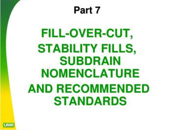
Buy this complete title here: https://goo.gl/6cMFcQFrontR.S.005Back57049Surveyor information stakePREVC-540CL029EL 834097C-2:1SE 2%CLE.P.3 50Ditch 010C- 020H.P.08C- 240SideSideIEW1C-Grade setter’s stakeRS2-foot bootCut cross sectionEL 83.40Surveyor’s hub2:1Original groundCut areaSloNEpeDitchHPEPCL2%4'' AC4'' ABFill54 feetLIFigure 1-1 Reading cut stakesONor other reference stake or point. It’s essential that you know how to readthe markings on these information stakes and follow the instructions theyprovide. The surveyor may write on one or all sides of the stake.Cut StakesThe stakes are usually called cut, fill or slope stakes, depending on the typeof excavation required. Figure 1-1 shows the kind of markings you’ll find on aninformation stake. In this case, we’re looking at a cut stake for a roadUNDERSTANDING ROAD SURVEY STAKESBut similar Craftsman Book Co. titles here: www.Craftsman-Book.com7
Buy this complete title here: https://goo.gl/6cMFcQexcavation. The front, back and both sides of a cut stake are shown in thefigure. Below the stake there’s a cross section drawing of the existing gradeand final road grades that are described on the stake. Refer to the drawing as Iexplain the markings on the information stake in the figure.PREVIEWLook first at the stake labeled front in the upper left of Figure 1-1.That’s the front of the information stake. The RS at the top of the stakemeans that there’s a reference stake to be established, and that referencestake is the point from which measurements and elevations are taken. Thelocation of the reference stake is the point that the projected cut slopemeets or catches original ground, also referred to as a catch point. Findthe reference stake in the drawing. It’s labeled RS and it’s in the upperleft-hand corner of the drawing. Below the letters RS on the informationstake you see C-10. Below that you see a diagonal line and 50. Thesemarkings above and below the diagonal line identify the amount of cutand distance needed to establish the correct grade at the reference stake.The number above the diagonal line is the elevation and the numberbelow the diagonal line is the distance. In this case, the information stakeshows a cut of 1.0 foot (below the level of the surveyor’s hub) to be made5.0 feet from the hub for the RS point.Some surveyors may use RP instead of RS. RP means reference point.Treat it exactly the same as the RS.LINENotice that distances and elevations are measured in feet and tenths(or hundredths) of a foot, not feet and inches. The small number above thesmall horizontal line shows decimals of a foot. That’s a little differentfrom what you’re probably used to, but you’ll appreciate the differencewhen adding and subtracting feet and decimals of a foot rather than feet,inches and fractions of an inch. I’ll explain more about this measuringsystem, called engineer’s measure, later in this chapter.ONThe two horizontal lines below the first set of measurements are veryimportant. All measurements above the double horizontal line are takenfrom the hub beside the information stake. The double horizontal linemeans and then, indicating that all measurements and elevations fromthat point down on the stake are taken from the RS point and not thesurveyor’s hub. Note this very carefully: If the double horizontal line wasreplaced with a single horizontal line, all measurements and elevationswould be taken from the surveyor’s hub rather than reference stake orhub established by the grade setter. On the other hand, if the surveyoruses a double line after each grade, then each cut becomes the referencefor the next. We’ll look at this last method shortly.8EXCAVATION & GRADING HANDBOOKBut similar Craftsman Book Co. titles here: www.Craftsman-Book.com
Buy this complete title here: https://goo.gl/6cMFcQIEWThe next information on this stake shows the elevation andlocation of the ditch cut (C-100 / 200). It’s to be 10 feet lower than theRS point and 20 feet from it. The grade falls 10 feet over a horizontaldistance of 20 feet, thus creating a 2:1 slope. You can see thisindicated on the drawing (about lower middle). For every foot of cut,the grade line moves horizontally 2 feet. Notice that allmeasurements are made from the reference stake. The ditch is cut10 feet below the reference stake and 20 feet from that stake. Alsonote that the 20-foot distance is measured horizontally, notdiagonally, from the reference stake. Look again at the drawing to besure you understand how the 20-foot distance to the ditch ismeasured. Remember, each square on the survey drawing represents1 horizontal and 1 vertical foot.PREVThe next reading is the hinge point (HP) grade and distance. Notethe hinge point on Figure 1-1. It’s 2 feet above the ditch cut. The HPinformation on the stake shows an 8-foot cut at 24 feet, indicating thegrade must come up 2 feet and move out 4 feet. By computing theamount the HP rises from the ditch and the distance it movestowards the center of the road, you can see that it’s again a 2:1 slope.NEReading down the information stake, the next grade and distanceis the edge-of-pavement (EP) point. The grade will be 7.9 feet belowthe reference stake hub. Notice the cut at EP is 0.10-foot less thanthe HP cut. The reason for this is that the road grade rises 2 percentin the 5 feet from HP to EP. Multiplying 5 feet by 2 percent gives theamount the shoulder rises in that distance (5.00 0.02 0.10).ONLIThe next markings give the centerline cut. You can see that thecut is again less than the previous cut at EP. Subtracting the 29 feetat EP from the 49 feet to the centerline leaves 20 feet. So thecenterline is 49 feet from RS and 20 feet from EP. The cut at thecenterline is 0.40 foot less than EP cut, making the centerline 0.40foot higher than EP. Again, we have a 2 percent slope from thecenterline to EP. You can check this by multiplying the 20 feet by 2percent (20.00 0.02 0.40). These are all finished grades so thegrade setter must add the thickness of the road section to the EPand centerline grade to get the correct subgrade elevation that mustbe excavated.Look at the back of the cut stake. It’s marked 3 50, indicatingthat this station is 350 feet from station 0 00, the point from whichthe survey began. Below the station number is the distance from theUNDERSTANDING ROAD SURVEY STAKESBut similar Craftsman Book Co. titles here: www.Craftsman-Book.com9
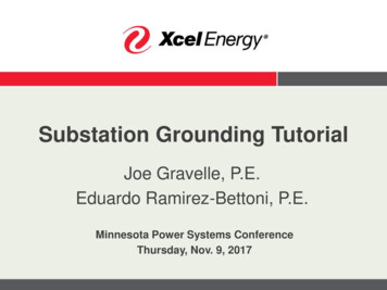
Buy this complete title here: https://goo.gl/6cMFcQsurveyor’s hub to the center of the road. Thisincludes 5 feet to the RS and 49 feet from the RS tothe centerline, a total of 54 feet (540).FrontR.S01C-05DitchNow let’s look at the sides of the stakes. Note thefirst drawing of the stake labeled side. This side ofthe stake identifies the percentage of slope from thecenterline to HP. The minus sign indicates that thecenterline slopes downto the HP. If it were a plus05sign instead, the centerline would be sloping up tothe HP. The second side stake drawing shows therate the cut slope falls from RS to the ditch. In thiscase, it’s 2 feet out for every foot downward. Thesecond group of numbers is the elevation of thesurveyor’s hub above sea level.010C-0IEW20H.P.0F-2E.P.0410F-0PREV05Here’s another method a surveyor might use toindicate measurements and elevations. I mentionedF-0earlier that the line between each grade on the020surveyor’s information stake was very important. Adouble horizontal line means and then. So, if thesurveyor uses a double line after each grade on theFigure 1-2 Cut stakeinformation stake, then each cut becomes thewith double linesreference for the next. The information stake inFigure 1-2 shows the same information as the one inFigure 1-1, except it’s written with a double line between each grade.Notice that by adding the double line, the last three distances change.40NECLONLIIn Figure 1-2, if you add the distances on the stake to centerline together(the distances indicated under the diagonal lines), you’ll get 54 feet from thesurveyor’s hub to centerline. Now look at the back of the stake in Figure 1-1.It also reads 54 feet to centerline from the surveyor’s hub. By using thedouble lines between grades, the last three cuts in Figure 1-1 become fills inFigure 1-2. The reason is because the HP grade must now be computed fromthe ditch grade, which is 2 feet lower, creating a fill of 2 feet. This method isalso used to determine the centerline grade. The EP grade is 0.10 foot higherthan the HP, and the centerline is 0.40 foot higher than EP.If you encounter a stake marked like the one shown in Figure 1-2, forbetter control and accuracy you should set a hub at each point as areference to shoot your next grade from. If you study Figures 1-1 and 1-2carefully, you’ll notice each distance and elevation are exactly the same.Only the methods for computing them are different.10EXCAVATION & GRADING HANDBOOKBut similar Craftsman Book Co. titles here: www.Craftsman-Book.com
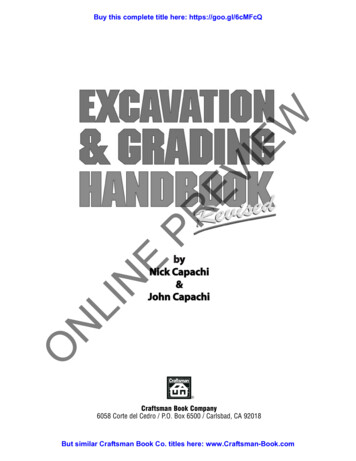
Buy this complete title here: https://goo.gl/6cMFcQ.50 (five tenths)56.45 (forty-five hundredths)5.40 (four tenths)4.35 (thirty-five hundredths)4.33 4''.30 (tenths)IEW3.25 (twenty-five hundredths)32.20 (two tenths).17 2''2PREV.15 (fifteen hundredths)11.10 (one tenth).05 (five hundredths)TenthsInches.01 .02 .03 .04 (hundredths)Figure 1-3 Compare inches with decimals of a footNEComparison of Inches and Decimals of a FootNLISetting grades requires many additions and subtractions. Usingdecimals speeds the work and makes errors less likely. Figure 1-3 comparesinches with decimals of a foot. If you’re uncomfortable reading distances intenths and hundredths of a foot, think of one foot as being like a dollarbill. One dollar is the same value as 100 pennies; one foot is the samedistance as 100 hundredths of a foot. One dollar is the same value as 10dimes; a foot is the same distance as 10 tenths of a foot. Pennies arehundredths. Dimes are tenths.OFill StakesWe’ve looked at a cut stake where material must be excavated toreduce the existing grade to the finish grade (Figure 1-1). Figure 1-4shows a typical fill situation where soil has to be deposited to build up theexisting grade. Again, the illustration shows four sides of the stake andthe road cross section. The RS at the top of the stake means that theUNDERSTANDING ROAD SURVEY STAKESBut similar Craftsman Book Co. titles here: www.Craftsman-Book.com11
Buy this complete title here: https://goo.gl/6cMFcQ35 feetFill cross sectionFill StakeCLGrade setter’s stakeEPHPSurveyor’sinformationstake4'' AC3%9'' AB2-foot bootFillOriginal groundIEWRSSurveyor’s hubEach square 1 LF-52:1 EL 9660E.P.SE 3%01025 00H.P.0F-503PREVEl 96.60Figure 1-4 Reading fill stakesONLIreference stake (to the right of the hub) is the starting point and the placefrom which all measurements and grades are measured. Cut or fillinformation given for the RS point will be measured from the surveyor’shub. Here, the RS is located 1.8 feet above the hub and 3 feet from it. Thegrade setter will have to set the reference stake at the indicated horizontaldistance from the hub and draw a horizontal line on the stake at theelevation given on the surveyor’s information stake. If the ground hasn’tbeen disturbed at that point, his line will match the existing ground.The grade setter should add a boot to his stake with a horizontal line 1foot above his RS grade. Because this is a fill, if the fill is made correctly,the overfill will cover his finished grade line. By placing a 1-foot bootabove his finished mark, he’ll save the time it would take him to dig it out12EXCAVATION & GRADING HANDBOOKBut similar Craftsman Book Co. titles here: www.Craftsman-Book.com
Buy this complete title here: https://goo.gl/6cMFcQlater. So when the grade setter returns to set a second slope stake at HP,he can use the 1-foot boot to compute the next vertical grade needed. He’lljust subtract his 1-foot boot from the vertical grade he wants.PREVIEWReading down the surveyor’s stake, the two horizontal lines mean andthen, indicating that the grade setter must measure from the RS point forthe next fill and distance, instead of measuring or shooting grades fromthe original surveyor’s hub. For the hinge point (HP), measure 10 feetfrom the RS hub or lath. At this point, a fill of 5 feet must be made toobtain the required grade. The hinge point is the place where the fill slopestops and the road grade begins. A stake won’t be set at HP until the fillreaches that point. It would be in the way. The operator will get that gradefrom the RS stake set by the grade setter. It’ll show the fill needed 10 feetout, and that the fill slope should be 2:1 for the HP grade. If the fill wereto be 20 feet high (rather than 5 feet), the grade setter would set slopestakes every 5 feet the fill rises to HP.LINEThere are times when the grade setter must offset the reference stake.Let’s look at how he would do this. We’ll say that the grade setter set hisreference stake 5 feet out from the surveyor’s hub. It often happens thatthe ground level is disturbed during clearing. What if, during the clearingoperation, 1 foot of the existing ground is removed and the grade at theRS no longer matches the surveyor’s information stake? When there is a 1foot difference in grade, the grade setter working a 2:1 fill should movethe reference stake back 2 feet. He must then mark his RS lath to reflectthe change. His new fill and distance to HP will be F-60 / 120. By movingthe RS 2 feet back, once the fill is made 1 foot high at a 2:1 slope, it willmatch the grade and distance on the original RS set at 5 feet. If he didn’tdo this, the slope would be off line with the remaining RS points that werenot undercut during clearing.ONOn a cut slope, you may have to offset the RS for the equipment. You’dagain move the RS back 2 feet to provide clearance for the grader’s blade.This will keep the grader operator from having to slow down and adjusthis cutting edge in from its normal grading position to avoid the stake.The grader would use the same cut and fill given for the 5-foot RSdistance, but the grade setter would mark a 2 in a circle at the top of hislath to indicate the actual RS point is offset 2 feet. He should also markthe actual RS point with a paint line for the grader operator to follow. It’svery important to set the RS point precisely because it controls the entirecut or fill elevation and alignment.UNDERSTANDING ROAD SURVEY STAKESBut similar Craftsman Book Co. titles here: www.Craftsman-Book.com13
Buy this complete title here: https://goo.gl/6cMFcQLet’s return to reading the information stake in Figure 1-4. The nextpoint referenced is the EP. This is the edge of the pavement and it showsa fill of 5.12 feet (F-512) at 14.0 feet from RS.IEWBelow the EP data is the centerline, represented by a C and an L (oneoverlapping the other). From the RS, you measure 32 feet and fill 5.66feet. This will put the centerline 18 feet from the EP and 0.54 foot higher.PREVThe back of the stake has 25 00. That signifies that this stake is 2,500feet up the line from the point where the measurements started (thebeginning of the road construction in this instance). The point thesurveyors start from is most likely marked 0 00. These are stationnumbers. The number 35.0 below CL means that the center of the road is35 feet out from the surveyor’s hub (not RS). Look again at the front ofthe stake and notice that when the RS distance of 3 feet is added to the CLdistance of 32 feet, the total is 35 feet, the same distance as that markedon the back of the stake.NEThe first stake labeled side is marked SE 3%. This is the percentagethat the roadbed slopes from the centerline to the hinge point. On theright-hand stake marked side, the first reading is 2:1 (2 to 1). This is therate the fill slope will rise from RS to HP. Notice that the front of thestake shows HP with a 5-foot fill over a 10-foot distance. This is what the2:1 indicates. The next item on the side stake is EL 9660. This is theelevation of the hub at the surveyor information stake. The surveyorscomputed all cuts or fills from that hub.NLIWhat I’ve described so far in this chapter is more or less standardprocedure for indicating elevations and distances on road stakes. However,surveyors in some counties and cities follow slightly different procedures.Some surveyors provide more information on the stakes and some less. Thesurveyor stake in Figure 1-5 shows what you might see on some county orcity road stakes.OThe front of the stake begins with a 2 with a circle around it. Thisindicates that the first cut starts 2 feet out. The next markings indicate thatthe ditch cut is 4 feet at a distance of 10 feet from the stake. The slope willagain be 2:1 because the first 2 feet aren’t cut and the cut over the next 8feet is 4 feet. Look at the figure again. Notice that there’s no double andthen line. This means that you must take all measurements and grade shotsfrom the hub set by the surveyors rather than from an RS or RP point, ason the previous stakes we’ve looked at.14EXCAVATION & GRADING HANDBOOKBut similar Craftsman Book Co. titles here: www.Craftsman-Book.com
Buy this complete title here: 260IEWShoC-350@ 130El 82562:1 8 00DitchC - 40@100Figure 1-5 Surveyor information stakesLINEReading down the stake, we find a second group of numbers that showthe top of the shoulder cut (Sho). This is the HP, or hinge point, referredto on previous stakes. Notice there’s no EP distance or elevation on thisstake. You must look at the plans for the distance from the shoulder tothe edge-of-pavement, and the elevation. Notice that there’s only 13 feetfrom the shoulder to the centerline, which indicates a possible aggregateshoulder. In this case the shoulder would be brought up to subgrade andnot finished grade.ONEngineering companies follow different conventions when markingtheir stakes. But the plans should clarify what’s intended and whichpoints are actually indicated. If something isn’t clear, don’t guess. Call theengineering company that created the drawing and marked the stakes.They should be eager to help.The second drawing in Figure 1-5 is the back of the stake. It showsthe rate of fall of the cut slope (2:1) and the station number (8 00). Itdoesn’t have the centerline distance because all the front measurementsare from the hub and not an RS or RP point. Many stakes have just thedetails required to allow you to set the grades. Even though otherinformation may be absent, they always have the station number on theUNDERSTANDING ROAD SURVEY STAKESBut similar Craftsman Book Co. titles here: www.Craftsman-Book.com15
Buy this complete title here: https://goo.gl/6cMFcQDitchCurb stakeStreet stakechannel stake3CL5West topC-00West toeC-80@110IEWC-20F.G.T.B.C.C-150East toeC-80@150PREVEast topC-00@230HubHubHubFigure 1-6 Miscellaneous information stakesLINEback. The side of the stake is shown in the right-hand illustration. It givesthe elevation above sea level (EL 8256). In some cases the hub elevationwon’t be on the stake at all. It may be replaced with the percentage ofslope for the road, or both may be omitted entirely.Miscellaneous Information StakesONCurb stake — Now look at Figure 1-6. The stake at the left is what you’dexpect the surveyor to set for cutting and setting curb grades. From thehub at the base of this information stake, you’d move out 5 feet and down1.50 feet to the top-back-of-curb (TBC) to set the curb forms or for the topof the concrete pour.In some cases, the surveyors may also give the front lip grade or eventhe flow line grade. If not, you’ll have to determine the distance from theback of the curb to the lip. This information is available in the plans or jobspecifications. When setting curb subgrade, determine the thickness of the16EXCAVATION & GRADING HANDBOOKBut similar Craftsman Book Co. titles here: www.Craftsman-Book.com
Buy this complete title here: https://goo.gl/6cMFcQIEWcurb plus any aggregate base, if it’s called for under the curb. Thethickness of one or both must be added to the cuts and subtracted from thefills to find the subgrade rather than the finished grade level. Notice thatthere’s a tack in the hub in front of the curb stake. The tack marks theexact spot from which the surveyor took his measurements. Without thismarker, the measurements could be as much as 11/2 inches off (using a2 2-inch hub). The tack provides greater accuracy.PREVStreet stake — The center stake in Figure 1-6 is a street stake you’dexpect to find on a rural road first cut. The front of the stake indicates thecenterline of the street and the cut or fill to the finished grade. In thiscase, there’s a 2-foot cut to the finished grade (FG). The plans shouldshow the road width, percentage of slope or crown, and the thickness ofthe road section. Remember to add the thickness of the road to this cut.The station number may be on the back or front of the street stake.Surveyors rarely stake the street centerline. The stakes are usually offsetbehind the back of the curb or a roadside ditch and will carry enoughinform
1. Excavation. 2. Roads--Design and construction. 3. Earthwork. I. Capachi, John, 1963- II. Capachi, Nick, 1934- Excavation & grading handbook. III. Title. TA730.C28 2006 624.1'52--dc22 2006015163 First edition 1978 Craftsman Book Company Second edition 1987 Craftsman Book Company Third edit