Transcription
Dell PowerStore: Introduction to the PlatformJuly 2022H18149.8White PaperAbstractThis white paper provides an overview of the PowerStore platform. Itdetails the value proposition, architecture, and various deploymentconsiderations of the available PowerStore appliances.Dell Technologies
CopyrightThe information in this publication is provided as is. Dell Inc. makes no representations or warranties of any kind with respectto the information in this publication, and specifically disclaims implied warranties of merchantability or fitness for a particularpurpose.Use, copying, and distribution of any software described in this publication requires an applicable software license.Copyright 2020-2022 Dell Inc. or its subsidiaries. All Rights Reserved. Dell Technologies, Dell, EMC, Dell EMC and othertrademarks are trademarks of Dell Inc. or its subsidiaries. Intel, the Intel logo, the Intel Inside logo and Xeon are trademarksof Intel Corporation in the U.S. and/or other countries. Other trademarks may be trademarks of their respective owners.Published in the USA July 2022 H18149.8.Dell Inc. believes the information in this document is accurate as of its publication date. The information is subject to changewithout notice.2Dell PowerStore: Introduction to the Platform
ContentsContentsExecutive summary.4Introduction .5PowerStore overview .8Hardware overview.9PowerStore T models .33PowerStore X models .39Conclusion.44References .45Dell PowerStore: Introduction to the Platform3
Executive summaryExecutive summaryOverviewDell PowerStore is designed with three purpose-built platforms. The 2U, two-node, dualsocket Intel Xeon platform is used for the PowerStore 1000, 3000, 5000, 7000, and9000 models. The 2U, two-node single-socket Intel Xeon platform is used for thePowerStore 500 model. The 2U, two-node dual-socket upgraded Intel Xeon platform isused for the PowerStore 1200, 3200, 5200, and 9200 models. PowerStore provides adata-centric, intelligent, and adaptable infrastructure that supports both traditional andmodern workloads. This white paper details the hardware platform, drives, and variousphysical components. This document includes cabling and deployment guidance for allPowerStore model appliances.AudienceThis document is intended for IT administrators, storage architects, partners, and DellTechnologies employees. The audience also includes any individuals who may evaluate,acquire, manage, operate, or design a Dell networked storage environment usingPowerStore systems.RevisionsWe value yourfeedbackDateDescriptionApril 2020Initial release: PowerStoreOS 1.0.0September 2020Minor updatesDecember 2020PowerStoreOS 1.0.3 updates: Discoverythrough static IPJanuary 2021Hardware overview and Metro node updatesApril 2021PowerStoreOS 2.0.0 updatesJune 2021Minor updatesJanuary 2022PowerStoreOS 2.1.0 updates; templateupdateApril 2022PowerStoreOS 2.1.1 updatesJuly 2022PowerStoreOS 3.0 updatesDell Technologies and the authors of this document welcome your feedback on thisdocument. Contact the Dell Technologies team by email.Authors: Ethan Stokes, Ryan MeyerNote: For links to other documentation for this topic, see the PowerStore Info Hub.4Dell PowerStore: Introduction to the Platform
IntroductionIntroductionPowerStore keyfeaturesIn this constantly changing world of increasing complexity and scale, the need for aneasy-to-use, intelligent storage system has only grown greater. Organizations that usenew applications and solutions require dependable storage and often face the challengeof doing more with less. PowerStore addresses this challenge by packaging a powerfulstorage system into a cost-efficient and space-efficient profile. Key PowerStore featuresand benefits include: Active/active architecture: PowerStore uses both nodes to serve host I/O andrun data operations in an active/active manner. This design efficiently uses allavailable hardware resources and optimizes performance, cost, and density indata centers. NVMe platform: PowerStore is designed to use the latest storage and interfacetechnologies to maximize application performance and eliminate bottlenecks.PowerStore can maximize performance with NVMe flash storage and supportsIntel Optane storage class memory (SCM) which approaches the speed ofDRAM. PowerStore supports front-end NVMe connectivity with NVMe overFibre Channel and NVMe over TCP, for a complete end-to-end NVMe solution. AppsON: Integration of the PowerStore container-based architecture withonboard VMware ESXi results in a new level of consolidation for enterprisestorage. This consolidation provides the benefits of a local, on-array applicationenvironment and integrates with the VMware vSphere managementenvironment and server resources. This ability allows users to bring applicationscloser to storage by running applications as virtual machines that run directly onPowerStore. AppsON enables agility for application deployments and allowsseamless movement between the PowerStore appliances and VMware ESXiservers. It also helps reduce the server and networking footprint for spaceefficient edge and remote deployments. Complemented by joint engineeringwork with VMware and Intel, AppsON uses intellectual property to bypass thehypervisor. This ability enables bare-metal NVMe performance with full supportfor plug-and-play functionality and PCIe fault containment. VMware integration: PowerStore is designed to have deep integration withVMware vSphere including VAAI, VASA, event notifications, snapshotmanagement, VMware vSphere Virtual Volumes (vVols), and virtual machinediscovery and monitoring in PowerStore Manager. Unified offering: PowerStore has a single architecture for block, file, and vVols.This architecture uses the latest technologies to provide flexible functionalitywithout sacrificing the cost-effective nature of enterprise storage. PowerStoreprovides storage in multiple formats to applications, ranging from physical andvirtual volumes to containers and traditional files. This ability provides theultimate workload flexibility and enables IT to simplify and consolidateinfrastructure. A modern, simple interface: PowerStore Manager, the PowerStoremanagement interface, is built with the data-center administrator in mind. Usingbrowser-native HTML5, PowerStore Manager can be used across variousDell PowerStore: Introduction to the Platform5
Introductionoperating systems and web browsers without requiring an external managementserver or appliance.Terminology Inline data reduction: Data reduction technologies play a critical role inenvironments in which storage administrators are attempting to do more withless. PowerStore data reduction supports this effort by optimally reducing theamount of physical storage that is required to save a dataset. PowerStore datareduction provides space savings by using software data deduplication andcompression through hardware assist. The storage system always enables andintelligently controls data reduction. Native data protection: Security and availability of data are critical concerns formany organizations, and PowerStore storage offers multiple solutions toaddress this need. Snapshots provide point-in-time copies of block, file, andvirtual machine data that can be used for backup and restoration purposes.Asynchronous replication offers an IP-based replication strategy within a systemor between two systems. Data at Rest Encryption (D@RE) ensures that userdata on the system is protected from physical theft and can substitute drivedisposal processes, such as shredding.The following table provides definitions for some of the terms that are used in thisdocument.Table 1.6TerminologyTermDefinitionApplianceSolution containing a base enclosure and any attachedexpansion enclosures. The size of an appliance could be onlythe base enclosure or the base enclosure plus expansionenclosures.Base enclosureEnclosure containing both nodes (node A and node B) and 25xNVMe drive slotsClusterOne or more appliances in a single grouping and managementinterface. Clusters are expandable by adding more appliancesto the existing cluster, up to the allowed amount for a cluster.Expansion enclosureEnclosures that can be attached to a base enclosure toprovide additional storage.Fibre Channel (FC) protocolProtocol used to perform IP and SCSI commands over a FibreChannel network.File systemStorage resource that can be accessed through file-sharingprotocols such as SMB or NFS.iSCSIProvides a mechanism for accessing block-level data storageover network connections.Network-attached storage(NAS) serverFile-level storage server used to host file systems. A NASserver is required to create file systems that use SMB or NFSshares.Network File System (NFS)An access protocol that allows data access from Linux or UNIXhosts on a network.Dell PowerStore: Introduction to the Platform
IntroductionTermDefinitionNodeStorage controller that provides the processing resources forperforming storage operations and servicing I/O betweenstorage and hosts. Each PowerStore appliance contains twonodes.NVMe over Fibre Channel(NVMe/FC)Protocol used to perform Non-Volatile Memory Express(NVMe) commands over a Fibre Channel network.NVMe over TCP (NVMe/TCP)Protocol used to perform Non-Volatile Memory Express(NVMe) commands over an Ethernet network.PowerStore Command LineInterface (PSTCLI)Interface that allows a user to perform tasks on the storagesystem by typing commands instead of using the userinterface.PowerStore ManagerAn HTML5 user interface used to manage PowerStoresystems.PowerStore RepresentationalState Transfer (REST) APISet of resources (objects), operations, and attributes thatprovide interactive, scripted, and programmatic managementcontrol of the PowerStore cluster.PowerStore T modelContainer-based storage system that is running on purposebuilt hardware. This storage system supports unified (blockand file) workloads, or block-optimized workloads.PowerStore X modelContainer-based storage system that runs inside a virtualmachine that is deployed on a VMware hypervisor. Besidesoffering block-optimized workloads, PowerStore also allowsusers to deploy applications directly on the array.Server Message Block (SMB)An access protocol that allows remote file data access fromclients to hosts on a network. SMB is typically used inMicrosoft Windows environments.SnapshotA point-in-time view of data stored on a storage resource. Auser can recover files from a snapshot, restore a storageresource from a snapshot, or provide access to a host.Thin cloneRead-write copy of a volume, volume group, file system, NASserver, or snapshot that shares blocks with the parentresource.VolumeA block-level storage device that can be shared out using aprotocol such as iSCSI or Fibre Channel.vSphere API for ArrayIntegration (VAAI)A VMware API that improves ESXi host utilization by offloadingstorage-related tasks to the storage system.vSphere API for StorageAwareness (VASA)A VMware vendor-neutral API that enables vSphere todetermine the capabilities of a storage system. This featurerequires a VASA provider on the storage system forcommunication.vSphere Virtual Volumes(vVols)A VMware storage framework which allows VM data to bestored on individual Virtual Volumes. This ability allows for dataservices to be applied at a VM-level of granularity andaccording to SPBM. Virtual Volumes can also refer to theindividual storage objects that are used to enable thisfunctionality.Dell PowerStore: Introduction to the Platform7
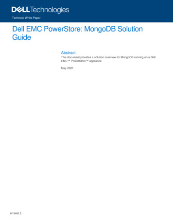
PowerStore overviewPowerStore overviewPowerStore achieves new levels of operational simplicity and agility. It uses a containerbased microservices architecture, advanced storage technologies, and integratedmachine learning to unlock the power of your data. A versatile platform with aperformance-centric design, PowerStore delivers multidimensional scale, always-on datareduction, and support for next-generation media.PowerStore brings the simplicity of public cloud to on-premises infrastructure, streamliningoperations with an integrated machine-learning engine and seamless automation. It offerspredictive analytics to easily monitor, analyze, and troubleshoot the environment.PowerStore is highly adaptable, providing the flexibility to host specialized workloadsdirectly on the appliance and modernize infrastructure without disruption. It also offersinvestment protection through flexible payment solutions and data-in-place upgrades.Besides the traditional consumption option, many PowerStore models make up theunderlying storage infrastructure for Dell Technologies APEX Data Storage Services. Thisallows customers to use a PowerStore solution in an as-a-Service model for ultimatesimplicity and agility.Figure 1.PowerStore applianceThe PowerStore platform is available in two different product model types: PowerStore Tand PowerStore X. PowerStore T models are bare-metal, unified storage arrays whichcan service block, file, and vVol resources along with numerous data services andefficiencies. PowerStore T models are perfect for traditional and modern workloads, withexamples including relational databases, electronic medical record applications, contentrepositories, and many more.PowerStore X model appliances enable running applications directly on the appliancethrough the AppsON capability. A native VMware ESXi layer runs embedded applicationsalongside the PowerStore operating system, all in the form of virtual machines. Thisfeature is in addition to the traditional storage functionality of PowerStore X modelappliances, which supports serving external block and vVol storage to servers with FCand iSCSI. This innovative design is perfect for storage-heavy applications, providingadditional compute and high-performance storage to an existing environment, or anyscenario where density, performance, and availability are primary factors.Beyond the power of a single PowerStore model appliance, multiple PowerStore modelappliances can be grouped into a cluster. A PowerStore cluster can consist of a singleappliance or scale up to four PowerStore appliances in a single cluster. The cluster enablesscaling the compute, storage, and connectivity of the PowerStore solution while managingmultiple appliances from a single control plane. It can also migrate resources betweenappliances and intelligently load balance new applications based on storage metrics.8Dell PowerStore: Introduction to the Platform
Hardware overviewMetro node is an external hardware and software add-on feature for PowerStore, and itprovides active/active synchronous replication plus standard local use cases. It also providesa solution locally with the local mirror feature to protect data from a potential array failure. Bothuse cases provide solutions for true continuous availability with zero downtime.PowerStore is viewed by metro node as an Asymmetric Logical Unit Access (ALUA) arraybased on SCSI response data, and is required to follow the four-active, four-passive pathconnectivity rules. This rule states that both nodes of the metro node must each have fouractive and four passive paths to all volumes provisioned from the array. For moreinformation about Metro node, see the solution brief Dell PowerStore metro mode.In PowerStoreOS 3.0, PowerStore appliances now support native metro volumereplication. This provides synchronous replication of spanned block storage volumes in anactive/active configuration across two PowerStore clusters in metro distance for VMFSdatastores.For more information about Metro Volume support, see the white paper DellPowerStore: Replication Technologies on the Dell Technologies Info Hub.Hardware overviewIntroductionThe purpose-built PowerStore system is offered in multiple physical hardware models inboth PowerStore T and PowerStore X appliances. The PowerStore T model series startswith the PowerStore 500 and scales up to the PowerStore 9200T. The PowerStore Xmodel series starts with the PowerStore 1000X and scales up to the PowerStore 9000X.A letter T or X may be listed at the end of the model number, indicating whether thespecific appliance is a PowerStore T or PowerStore X model, respectively. For eachmodel numeral, such as 1000 (for PowerStore 1000T or 1000X models), the hardwarespecifications are identical. The two different PowerStore options are often grouped whenhardware is referenced, and the T or X is omitted from the model number. See Table 3 formodel comparisons.The PowerStore 500 model was introduced in the PowerStoreOS 2.0 release. This modelruns on a dual-node, single-socket Intel Xeon platform and runs the PowerStoreOS 2.0and higher software. The PowerStore 500 runs the same PowerStoreOS as all otherPowerStore T models. PowerStoreOS 1.0 and all PowerStoreOS 1.0 service packs arenot supported on the PowerStore 500 appliance.In PowerStoreOS 3.0, four new PowerStore T models have been introduced ranging fromPowerStore 1200T up to PowerStore 9200T. These model appliances feature the samedual-node architecture with upgraded dual-socket Intel Xeon processors and aresupported on PowerStoreOS 3.0 and higher software. These models come with anupgraded Embedded Module which features back-end connectivity that supports theaddition of a new NVMe expansion enclosure. The NVMe expansion enclosure providesfull end-to-end NVMe support for data drives, allowing customers to expand their NVMetier outside of the base enclosure.The system limits vary depending on the PowerStore model. Learn more about thesystem limits on the Dell PowerStore Spec Sheet.Dell PowerStore: Introduction to the Platform9
Hardware overviewTable 2.PowerStore 500 and 1200-9200 model 3200TPowerStore5200TNVRAM drives02Maximum storagedrives (perappliance)9793Supported drivetypesNVMe SCM2, NVMe SSD4-port card25/10 GbEoptical/SFP andTwinax325/10 GbE optical/SFP and Twinax or 10GbE BASE-T2-port card10 GbEoptical/SFP andTwinax100 GbE QSFP 4Supported I/Omodules(2 per node)32/16/8/4 Gb FC4100 GbE optical/QSFP and copper active/passive525/10 GbE optical/SFP , and Twinax10 GbE BASE-TSupported expansionenclosuresUp to three 2.5-inch 24-drive NVMe SSD enclosures per appliance1PowerStore 500 and 1200 through 9200 models only offered as a PowerStore T.2NVMe SCM SSDs only supported in base enclosure.3Ports 2 and 3 on the 4-Port card on PowerStore 500 are reserved for NVMe expansion enclosure.42-port card is reserved for back-end connectivity to NVMe expansion enclosure on PowerStore 1200 through 92005PowerStore 500 does not support the 100 GbE I/O module.Table 3.PowerStore 1000-9000 model comparisonPowerStore1000PowerStore3000NVRAM drives2Maximumstorage drives(per appliance)96Supported drivetypesNVMe SCM1, NVMe SSD, SAS SSD24-port card25/10 GbE optical/SFP and Twinaxor10 GbE BASE-T2-port card-Supported I/Omodules(2 per node)32/16/8/4 Gb FCPowerStore7000PowerStore 90004100 GbE optical/QSFP and copper active/passive (PowerStore T only)25/10 GbE optical/SFP and Twinax (PowerStore T only)10 GbE BASE-T (PowerStore T only)10PowerStore5000Dell PowerStore: Introduction to the PlatformPowerStore9200T
Hardware PowerStore3000PowerStore7000PowerStore 90002.5-inch 25-drive SAS SSD1NVMe SCM drives only supported in base enclosure.2SAS SSD drives only supported in SAS expansion enclosure.High availabilityPowerStore5000PowerStore features fully redundant hardware and includes several high availabilityfeatures. These features are designed to withstand component failures within the systemitself and environmental failures such as network or power outages. If an individualcomponent fails, the storage system remains online and continues to serve data. Thesystem can also withstand multiple failures if they occur in separate component sets. Afterthe administrator is notified about the failure by call-home or onboard system alerts, theycan order and replace the failed component without impact.PowerStore is a dual-node architecture which includes two identical nodes forredundancy. It features an active/active controller configuration where both nodes areservicing I/O simultaneously. This increases hardware efficiency since there are norequirements for idle standby hardware. These nodes, along with up to twenty-five 2.5inch drives, are enclosed within the base enclosure, all in a 2U form factor.The following sections cover the different hardware components of the PowerStoreplatform. Specific sections detail the redundancy and high availability features of thatcomponent and how it pertains to PowerStore. For more information about highavailability at the software and cluster level, see the document PowerStore: Clusteringand High Availability.Base enclosureThe PowerStore base enclosure supports 25 all-NVMe 2.5-inch drives in a 2U chassis.The base enclosure is secured into a rack using toolless snap-in rails. The rails ship withevery system and allow for easy installation of a PowerStore system. The base enclosuresecurely latches onto the snap-in rails when fully inserted into the rack. If you mustremove the enclosure from the rails, lift a bottom latch on each side of the base enclosureto pull the base enclosure out. While the base enclosure securely latches onto the rails,there are optional screws underneath each latch which you can tighten for additionalstability when moving the rack.The front of the base enclosure contains an LED to display different states of the system.This LED is in the upper-left side of the chassis near drive slot 0. The LED states andcorresponding system status are shown in Table 4. Each of the 2.5-inch drives containboth a drive power and activity LED, and a drive fault LED. The drive fault LED illuminatesamber when a drive becomes faulted. There is also an option in PowerStore Manager toblink a specific drive to identify it using the fault LED. If the drive-power and activity LED ispowered on and active, it blinks blue.Table 4.Base enclosure LED status descriptionLED stateSystem statusBluePower is on. No fault has occurred.Dell PowerStore: Introduction to the Platform11
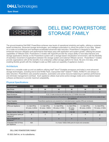
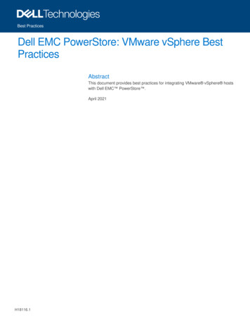
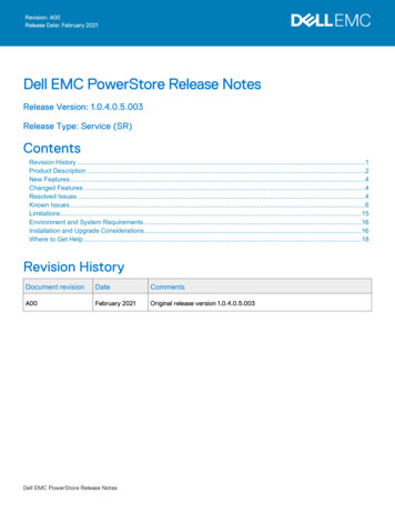
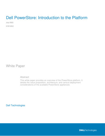
Hardware overviewLED stateSystem statusAmberPower is on. Fault has occurred within the enclosure.Blue after amber alternatingPower is on. System is not initialized.OffPower is off.The data storage drives are populated from left to right, starting in slot 0. PowerStorerequires a minimum of six storage drives. User data, metadata, and system data areautomatically stored and protected across the available storage drives using thePowerStore Dynamic Resiliency Engine (DRE). For more information about PowerStoreDRE, see the document PowerStore: Clustering and High Availability.PowerStore 1200 through 9200The PowerStore 1200 through 9200 model appliances are available starting inPowerStoreOS 3.0 as PowerStore T systems. The base enclosure for PowerStore 1200,PowerStore 3200, PowerStore 5200, and PowerStore 9200 models supports 25 all-NVMe2.5-inch drives in a 2U chassis. The following figure shows the base enclosure for aPowerStore system with 21 NVMe SSDs and four NVMe NVRAM drives.Figure 2.Base enclosure front viewThe back of the base enclosure reveals the nodes and their connectivity options (seeFigure 3). Each node has one embedded module and two optional I/O module slots forhost connectivity. Each node has a dedicated 1 GbE BASE-T service port which can beused for on-site support access and initial configuration of the system. Each node alsocontains a second 1 GbE BASE-T port which is used for management traffic. These 1GbE BASE-T ports are both provided on the embedded module of the node.For more information about the base enclosure and base enclosure components, see thePowerStore Hardware Information Guide.Figure 3.Base enclosure back viewDrivesThe base enclosure is an all-NVMe platform, capable of supporting NVMe SSD, NVMeSCM, and NVMe NVRAM drives. You can populate slots 0 through 20 with NVMe SSD orNVMe SCM drives. Slots 21 through 24 are reserved for NVMe NVRAM drives whichserve as write caching for user data. PowerStore 1200 and PowerStore 3200 models12Dell PowerStore: Introduction to the Platform
Hardware overviewcontain two NVMe NVRAM drives in slots 23 and 24. PowerStore 5200 and PowerStore9200 models contain four NVMe NVRAM drives in slots 21 through 24. In models thatonly use two NVMe NVRAM drives, slots 21 and 22 are not available for storage drives.PowerStore systems require a minimum of six NVMe SSD or six NVMe SCM drives,which can be scaled up in single-drive increments. Systems with at least six NVMe SSDdrives can support one or more NVMe SCM drives for metadata tiering. NVMe SCMdrives provide lower latency than NVMe SSD drives and can improve systemperformance by storing metadata on these low-latency drives. On a system that containsboth NVMe SCM and NVMe SSD, the NVMe SCM drives are dedicated to metadata andall user data is stored on NVMe SSD drives.PowerStore 1200 through 9200 model systems support up to three NVMe expansionenclosures per appliance for expanding capacity beyond the all-NVMe base enclosurewith additional NVMe SSDs. NVMe expansion enclosures are not supported on systemsthat contain entirely NVMe SCM drives. NVMe expansion enclosures are supported onsystems that have a mix of NVMe SSD and NVMe SCM in the base enclosure.NodeThe purpose-built PowerStore platform is powered by dual-socket upgraded Intel Xeon processors. Each purpose-built PowerStore system contains two nodes, which are usedfor high-availability and load-balancing purposes.Each node is 1U in size and stacks vertically in the base enclosure, with the top nodeinverted. The bottom PowerStore node is node A, and the top PowerStore node is nodeB. Each node can access each drive through the midplane connection inside the baseenclosure. Each node contains the following components, which are detailed in thefollowing sections: Internal M.2 boot module Fan modules Battery backup unit DIMMs Embedded module I/O module Power supplyInternal M.2 boot moduleEach node has a primary and a secondary M.2 SATA device inside the system on a risercard between DIMM slots 11 and 12 (see the following figure). The primary M.2 device is240 GB and the primary boot device for the node. PowerStore uses this device to storethe base operating system, log files, and for general system operations. The secondaryM.2 device is 120 GB. PowerStore uses this device for recovery during a primary M.2failure, and it is an alternate location for log files.Dell PowerStore: Introduction to the Platform13
Hardware overviewFigure 4.Internal M.2 boot moduleFan modulesPowerStore uses fan modules (cooling modules) to provide cool airflow to the nodeinterior to ensure that the internal components remain at optimal operating temperatures(see Figure 14 following figure). Each node contains seven redundant fan modules thatare connected to the motherboard within the node. A node can tolerate a single fanmodule fault, and the surviving fans increase their speed to compensate for the faultedmodule. If two fan modules fault within the same node, the node performs a protectivethermal shutdown. A protective thermal shutdown gracefully powers off the node, and anyresource fails over to the surviving node.Figure 5.Fan moduleBattery backup unitIf system power is lost, the battery backup unit (BBU) provides power to the NVRAM driveslots and the baseboard management controller (BMC). This action allows the NVRAMdrives to vault their volatile data to nonvolatile storage within the same drive and persistthe information. When the NVRAM drives have completed their vault, the BMC powers offthe system.The BBU in node A provides power for drive slots 21 and 23. The BBU in node B providespower for drive slots 22 and 24. The NVRAM drives are in mirrored sets consisting ofdrives in slots 23 and 24. If the PowerStore model supports four NVRAM drives, there isanother mirrored set in slots 21 and 22. The node BBUs are configured so that both BBUspower each NVRAM mirrored pair, ensuring that there is no single point of failure. EachBBU contains sufficient charge to accommodate multiple back-to-back power failures.When power is resumed, the BBUs gradually recharge.14Dell PowerStore: Introduction to the Platform
Hardware overviewFigure 6.Battery backup unitDIMMsEach node contains 24 DDR4 DIMM slots used for DRAM, which are populated indifferent configurations that are based on the PowerStore model. All host data is written tothe NVMe NVRAM drives from DRAM before the host is acknowledged, to protect againstdata loss upon system power failure.Figure 7.DIMMEmbedded moduleEach node contains a single embedded module that includes various connectivitycomponents. In PowerStoreOS 3.0, the PowerStore 1200, 3200, 5200, and 9200 modelscome with an upgraded embedded module where the SAS ports have been removed inorder to support a 100GbE 2-port card for NVMe expansion enclosures. The 2-port card isoptional at time of purchase and is required to supported NVMe exp
PowerStore Manager An HTML5 user interface used to manage PowerStore systems. PowerStore Representational State Transfer (REST) API Set of resources (objects), operations, and attributes that provide interactive, scripted, and programmatic management control of the PowerStore cluster.