Transcription
APC-104 Contents2001Norgren AirPreparation Productsand AccessoriesCompressed Air Systems . . . . . . . . . . . . . . . . . . . . . . . . . . . . . ALE-0-2Filters . . . . . . . . . . . . . . . . . . . . . . . . . . . . . . . . . . . . . . . . . . . . ALE-1-AOil Removal (Coalescing) Filters . . . . . . . . . . . . . . . . . . . . . . . ALE-2-1Oil Vapor Removal (Adsorbing) Filters . . . . . . . . . . . . . . . . . . . ALE-3-1Membrane Dryers . . . . . . . . . . . . . . . . . . . . . . . . . . . . . . . . . . . ALE-4-1Regulators . . . . . . . . . . . . . . . . . . . . . . . . . . . . . . . . . . . . . . . . ALE-5-ASpecialty Regulators. . . . . . . . . . . . . . . . . . . . . . . . . . . . . . . . . ALE-6-1Manifold Regulators . . . . . . . . . . . . . . . . . . . . . . . . . . . . . . . . . ALE-7-1Precision and Instrument Regulators . . . . . . . . . . . . . . . . . . . ALE-8-1Pilot Regulators . . . . . . . . . . . . . . . . . . . . . . . . . . . . . . . . . . . . ALE-9-1Pilot Operated Regulators . . . . . . . . . . . . . . . . . . . . . . . . . . . ALE-10-1U.L. Listed Cylinder Gas Regulators for Industrial Use . . . . . ALE-11-1U.L. Listed Beverage Regulators . . . . . . . . . . . . . . . . . . . . . . ALE-12-1Filter/Regulators . . . . . . . . . . . . . . . . . . . . . . . . . . . . . . . . . . . ALE-13-1Lubricators . . . . . . . . . . . . . . . . . . . . . . . . . . . . . . . . . . . . . . . ALE-14-APressure Relief Valves . . . . . . . . . . . . . . . . . . . . . . . . . . . . . . ALE-15-1Shut-Off and Lockout Valves . . . . . . . . . . . . . . . . . . . . . . . . . ALE-16-1Stainless Steel Products. . . . . . . . . . . . . . . . . . . . . . . . . . . . . ALE-17-1Smooth Start, and Directional Control Valves . . . . . . . . . . . . ALE-18-1Additional Products . . . . . . . . . . . . . . . . . . . . . . . . . . . . . . . . ALE-19-1Filter-Filter Combination Units . . . . . . . . . . . . . . . . . . . . . . . . ALE-20-1Filter/Regulator-Lubricator Combination Units . . . . . . . . . . . ALE-21-1Filter-Regulator-Lubricator Combination Units . . . . . . . . . . . ALE-22-1Filter-Lubricator Combination Units. . . . . . . . . . . . . . . . . . . . ALE-23-1Modular Components . . . . . . . . . . . . . . . . . . . . . . . . . . . . . . . ALE-24-1Accessories for Filters, Regulators, and Lubricators . . . . . . ALE-25-1Watson Smith Electronic Products. . . . . . . . . . . . . . . . . . . . . ALE-26-1Compressed Air Dryers . . . . . . . . . . . . . . . . . . . . . . . . . . . . . ALE-27-1Fittings and Accessories . . . . . . . . . . . . . . . . . . . . . . . . . . . . ALE-28-1Appendix/Technical Information. . . . . . . . . . . . . . . . . . . . . . . ALE-29-1Part Index . . . . . . . . . . . . . . . . . . . . . . . . . . . . . . . . . . . . . . . ALE-29-18Littleton, CO USAPhone 303-794-2611Fax 303-795-9487ALE-0-1
Compressed Air SystemsNorgren Air Preparation Products: Protecting yourpneumatic system from the hazards of contaminated air.T h e a i r l e a v i n g a c o m p r e s s o r i s h o t , d i r t y, w e t a n d g e n e r a l l y a t a h i g h e rpressure than the downstream equipment requires. A typical 100 scfm (50dm3/sec) compressor will push 1200 gallons (4500 liters) of water and 2 gallons(8 liters) of degraded compressor oil into the system in a year along withconsiderable amounts of dirt particles. Before this air can be used it needs to betreated to remove the contaminants, have its pressure reduced to the right level,and in many cases have oil added to lubricate downstream equipment.ALE-0-2Littleton, CO USAPhone 303-794-2611Fax 303-795-9487
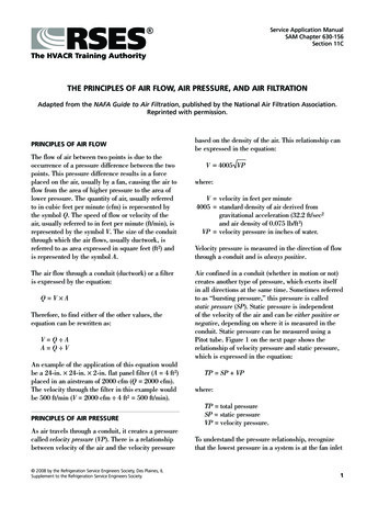
Compressed Air SystemsBuild Your System!These illustrations show three examples of how NorgrenAir Preparation Products have been used to design clean,safe, and efficient industrial compressed air systems. APilot Operated(Slave) RegulatorModular Excelon System Lockout Valve Filter/Regulator IR OPERATED TOOLS COMPRESSEDAIR FROMRECEIVER BModular Excelon System Lockout Valve Filter/Regulator Oil Removal FilterGeneralPurposeFilterPAINT SPRAYINGOil RemovalFilterAirDryerA SolenoidValveBearingLubricatorFilter Regulator torDrip LegDrainMACHINELUBRICATIONCYLINDERSReclassifieresB Filter/RegulatorOil RemovalFilterVaporRemoval FilterULTRA CLEAN AIR FORCRITICAL APPLICATIONSLockoutValveDrip LegDrainLittleton, CO USAPhone 303-794-2611Fax 303-795-9487ALE-0-3
Compressed Air SystemsNorgren knowledgeand products saveyou moneyAPPLICATIONSCompressed air isoften wrongly assumed tobe a cheap or even ‘free’source of power. In fact itcan be 10 times asexpensive as electricityby the time allgeneration, transmission,treatment and systemcosts are taken intoaccount. Good airpreparation musttherefore consider theenergy consumption ofthe system and airtreatment equipment.The following section shows several typical systemsof a generic type and the equipment normally usedfor the application. Remember every system shouldbe treated on its merits and broken down into severalelements to ensure optimum installation, runningand maintenance costs are achieved.The applications below are typicallybranches taken off a large works distribution mainsand isolating valves are usually placed in front of allbranches to permit isolation from the mains to allowfor maintenance to take place without recourse tocomplete plant shut-down.General Pneumatic Circuits:eg: directional control valves and cylinders, inmulti-valve circuits, machine cleaning, air motorsand high speed tools.A Micro-Fog lubricator is required for theseveral varying flow paths to ensure full lubrication.(Figure 2)Figure 2.Shut-off valve, filter/reg, Micro-Fog lubricator, softstart/dump, relief valve.Multiple Simple Applications:eg: OEM machines.The process of airpreparation has been atthe core of Norgren’sbusiness for over 70years. The aim of thisbooklet is to offerguidance on the correct,economic and safetreatment of compressedair in industrialapplications. Here we canonly provide a briefsummary of the extensiveexperience Norgren hasas a world leader in FRLt e c h n o l o g y.It is often a case that with fairly simplemachines, lubricated air is required for valving andpneumatic circuitry and oil-free air for air bearings.To keep costs low two separate lines areunnecessary and a typical arrangement from one airsupply only can be arranged as shown.Other elements such as pressure switchesand check valves may be made available withinmodular systems. (Figure 3).Figure 2Shut-off valve, filter/regulator, oil removal filter,porting block, Micro-Fog lubricator.ALE-0-4Littleton, CO USAPhone 303-794-2611Fax 303-795-9487
Compressed Air SystemsOil-Free Applications:eg paint spraying, foodstuffs, film processing,powders.Critical Pressure Control (Instrumentation):eg: precision regulation, fluidic systems, airgauging, process control.These applications need to be free fromany water deposits in the downstream system. Formany installations this will require air drying. Thedrying medium (for desiccant or deliquescentdryers) will need protecting from oil to allow it towork efficiently and the downstream system willalso need protection from accidental migration ofthe material into it. A typical arrangement would beas figure 26 and in some instances it might beworth considering an oil vapour removal filter too.(Figure 4)A typical arrangement is shown, where oilaerosols which can prevent fast response ofdownstream devices, need to be removed.Dependant upon air quality drying may not berequired. (Figure 6)Continuous ProcessesAnother facet of Norgren’s Olympian Plus is theability to make duplex systems. This is invaluablefor systems which cannot be shut-down, such ascontinuous process plant. Two identical air sets arejoined together and one may be isolated (andserviced) whilst the other set is in operation.(Figure 8)Figure 8.Figure 6.Figure 4.Duplex system: shut-off valve, filter/reg, lubricator,porting block, oil removal filter and shut-off valve x2 with manifold block connectors.Shut-off valve, general purpose filter, oil removalfilter, drier, oil removal filter, precision regulator.Shut-off valve, general purpose filter, oil removalfilter, drier, oil removal filter, regulator, relief valve.Heavy Duty Lubrication:eg: large slow moving cylinders.In such applications large amounts oflubricant are required for effective lubrication. Againa soft start/dump valve is shown but is dependentupon the application. (Figure 5).Direct Injection Lubrication:eg: conveyor chains.The application does not allow for‘fog’ type lubrication because of the surroundingenvironment and absence of a lubrication chamber.(Figure 7).Figure 7.Figure 5.Shut-off valve, filter/reg, Oil-Fog lubricator,soft start/dump valve, relief valve.Shut-off valve, filter/reg direct injectionlubricator.Littleton, CO USAPhone 303-794-2611Fax 303-795-9487ALE-0-5
Filter ContentsFiltersGeneral Purpose Filters, OilRemoval (Coalescing) Filters, OilVapor Removal (Adsorbing)Filters, and Compressed AirMembrane DryersFilter Overview . . . . . . . . . . . . . . . . . . . . . . . . . . . . . . .ALE-1-BRating Filter Elements and ISO Standard 8573-1 . . . .ALE-1-GGeneral Purpose Filters . . . . . . . . . . . . . . . . . . . . . . . . . .ALE-1Oil Removal (Coalescing) Filters . . . . . . . . . . . . . . . . . . .ALE-2Oil Vapor Removal (Adsorbing) Filters . . . . . . . . . . . . . .ALE-3Compressed Air Membrane Dryers . . . . . . . . . . . . . . . . .ALE-4Littleton, CO USAPhone 303-794-2611Fax 303-795-9487ALE-1-A
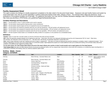
Filters1.1GENERAL PURPOSE FILTERService indicator(optional)BodyLouvreCentre postElementBowlBaffleyyy;;;yyy;;;yyy;;;yyy;;;Metal bowlsight glassDrainCOALESCING FILTERService indicatorBodyElementOuter sockBowlyyy;;;yyy;;;yyy;;;yyy;;;ALE-1-BMetal bowlsight glassCollectedcondensateDrainThree main types of filters exist: The generalpurpose filter for water and particles, the coalescingoil removal filter for oil aerosols and the activatedcarbon filter for the removal of oil vapors.The general purpose filter is used for mostfilter applications and is available from 1/8" to 2"pipe sizes. Uses are main headers, branch lines,tools, cylinders, valves and valve circuits, airagitators etc. Oil removal filters are used where veryclean, oil-free air is required, such as for the supplyto fluidic devices, instrumentation, air gaugingequipment and air bearings.Activated Carbon filters are used forsystems where the oil vapors in the air are notacceptable; such as instrumentation and paintspraying.1.1.1CollectedcondensateGENERAL OVERVIEWHow Do General Purpose Filters Work?The dirt and moisture-laden air enters the inlet portand is directed into the louvers which centrifugallyseparate the entrained liquids and dirt which fall tothe bottom of the bowl. Near the bottom of the bowla baffle creates a quiet zone, preventing theturbulent air re-entraining the contaminants. The air,now free of water droplets and large dirt particles,passes through the filter element which removessmall dirt particles. Solid particles eventually plugthe element necessitating replacement.1.1.2How Do Oil Removal Filters Work?Air enters the filter and passes through theelement from inside to outside, where oil aerosolsimpinge on the borosilicate micro-fibers and arecoalesced into larger drops. The drops are carriedthrough the element until they reach the outerporous sock. The outer sock, because of its cellularconstruction, retains these liquids and allows themto drain by gravity to the bottom of the bowl.Solid partilces are retained in the elementand cause the pressure drop to slowly increasethrought the working life of the element. When thepressure drop across the element reaches 10 psid,the service life indicator on top of the filter willshow more red than green and the element shouldbe replaced.Littleton, CO USAPhone 303-794-26111.1.3How do Vapor removal Filters Work?Carbon filters are used to remove oil vapors andodors. The activated carbon has a porous structurewhich results in a large surface area. The oil vaporsare attracted and adhere to this surface. There isusually a small sintered medium included in anactivated carbon element to prevent the carbonparticles from migrating downstream. The carbonfilter reduces the maximum oil content of air leavingthe filter to 0.003ppm at 70 F, i.e. To ISO 8573 class1.7.1. If protected upstream by general and oilremoval filters life is between 400 and 1000 hours.1.1.4 Why use a Pre-Filter?A pre-filter is simply a general purpose filter placedupstream of a higher grade filter to remove themajority of the water and larger particlecontaminants and thus lengthen the life of the highergrade filter element.A 5 micron pre-filter should always be usedahead of an oil removal filter.An oil removal (coalescing) filter must beused ahead of a vapor removal adsorbing filter.1.2AIR QUALITY1.2.1What is ISO 8573?(See ALE-1-G for specification)This is an international standard on air quality. Itcovers compressed air for general industrial use.The air quality is specified using a 3 digitcode expressing the remaining content of a specificcontaminant after the filter (or dryer).1.2.2Air Classes for Norgren Filters:Particulate filters condition compressed air todifferent degrees, dependent on the micron rating ofthe filter. The finer filter, 5 µm, will achieve ISO 8573class 3.7. or class 3. Applying a 40 µm filter willresult in ISO 8573 class 5.7. or class 5 air.Coalescing filters improve the quality ofdownstream air to ISO 8573 class 1.7.2, the particlesize is reduced down to 0.01µm, with a remainingoil content of less than 0.01ppm. Coalescing filterscannot remove oil which is in the vapor state in thesupply air. One way to remove vapor is to reduce thetemperature of the air flow allowing the vapor tocondense, alternatively remove the vapor chemicallyusing an activated carbon filter.Fax 303-795-9487
Filters1.31.2.3What Micron Ratings are Available?1.2.4The standard Norgren general purpose elements are40 and 5 microns, with 40 microns being suitablefor most industrial applications. Certain industrieshave 25 or 75 micron as a standard and someproduct ranges have these options available.For a given element size, the smaller themicron rating the higher the pressure drop acrossthe filter. The service life between cleaning is alsoless for the smaller micron filters, as small holesplug more quickly than bigger holes.Figure 1.RECOMMENDED FILTRATION LEVELS.ApplicationTypical Quality ClassesOilDirtAir agitation13Air bearings22Air gauging22Air motors44Brick and glass machines54Cleaning of machine parts34Construction45Conveying, granular products 24Conveying, powder products13Fluidics, power circuits25Fluidics, sensors23Foundry machines45Food and beverages11Hand operated air tools55Machine tools54Mining55Micro-electronics manufacture 11Packaging and textile machines 53Photographic film processing 12Pneumatic cylinders35Pneumatic tools54Pneumatic tools (high speed) 43Process control instruments32Paint spraying11Sand Blasting45Welding macines55General Workshop air54How do Service Life Indicators Work?The service life (pressure drop) indicator found ontop of coalescing or general purpose filters is greenwhen the filter is new. As a pressure differentialdevelops across the filter element with use, a springbiased red outer sleeve is pushed up. When morered is visible than green, then the pressuredifferential across the element is in excess of 10 psi(0.7 bar) and the element should be replaced.1.2.5When does the Carbon Pack Indicator TurnPink?The white ring around the base of the vaporremoval carbon pack turns pink in the presence ofliquid oil. Therefore if the ring turns pink thecoalescing filter is passing liquid oil and needsreplacing. If this occurs soon after the filter hasbeen installed then it usually indicates a seal failurein the coalescing filter. Remember that visualdetection is a not a substitute for scheduledmaintenance.1.2.6PLASTIC BOWLSHow Long does an Element Last?This depends entirely on the quality of the inlet air.If it is very poor the elements will need replacingmore frequently.In general, air service equipment shouldbe maintained annually. Use, quality of air andcondition at examination may indicate adjustmentof the maintenance interval.The following guidelines can be given:General Purpose Replace/maintain annually. TheFilter:element can lose 15% efficiencyeach time it is cleaned. Elementsare low cost, so it is advisable toreplace them.Coalescing:Evaluate after 12 months ofservicing. If the pressure dropacross the element exceeds 10psig (0.7bar) then the elementrequires changing.Activated Carbon Should be changed every 1,000Packs:hours usage or when odor isdetected. The life dependssignificantly on ambienttemperature.Littleton, CO USAPhone 303-794-2611Norgren transparent plastic bowls are made frompolycarbonate. Some competitors use othermaterials such as Grilamid.Both these materials are extremely resilient and havean excellent safety record. However thesetransparent plastics will degrade when subjected toexcessive heat, solvents and some chemicals, whichcan lead to crazing and finally bowl failure.Over the last few years metal bowls andguarded plastic bowls have become increasinglypopular driven by the emergence of guidelinesrecommending the use of guards.Some organizations have their own internalstandards which call for guarded plastic or metalbowl and the general market trend is away fromplastic bowls in the 1/2” or above port size units.This trend is reflected in our latest Excelon 74 andOlympian Plus product ranges. Plastic bowls remainthe most common option for 1/4” and smaller units.Never use polycarbonate bowls atconditions which exceed the maximum ratedpressure and temperature of 150 psig (10 bar) and125 F (50 C).Certain chemicals, common in some oilsand solvents, can attack polycarbonate and causethe bowl to burst. If the compressor intake is locatedin an area containing incompatible vapors, thesecontaminants can be drawn into the compressor andconveyed to the bowl in the compressed air. Thiscan result in bowl failure.Synthetic compressor oils may be drawn infrom the compressor and can also result in bowlfailure.If doubt exists as to the compatibility ofcertain fluids with polycarbonate, please contactApplications Engineering.Metal bowls should be used wheretemperatures exceed 125 F (50 C) and/or pressuresexceed 150 psig (10 bar), or when materials arepresent which are incompatible with polycarbonate.Maximum rated operating conditions for metalbowls depend on the range; check APC-104.Fax 303-795-9487ALE-1-C
Filters1.4DRAINS1.4.1Semi Automatic:1.4.4A semi-auto drain is one which operates when theair-line is depressurized eg at the end of a shift. It isa normally open two-way valve which is held closedby 7-10 psig (0.7-0.8 bar). When the filter ispressurized, the drain may be operated manually bypushing the tube, which protrudes outside the bowl,upwards.1.4.2Automatic:An automatic drain is a two-way valve, which willclose when the system is pressurized. The drainopens when the float rises due to accumulated liquidand on depressurization.1.4.3Where should an Automatic Drain be Used?Automatic Drains should be used where the filterlocation may make servicing difficult, where filtersmay be hidden from view and consequently beoverlooked or where equipment is in continual use.Areas where large quantities of liquid mayaccumulate over a short period of time should alsobe equipped with auto-drain filters. High labor costsfor draining a large number of filters manually willgenerally justify the use of auto-drains.Machines which have been shut down for along period of time, such as over a weekend, candraw slugs of water during start-up which canoverload a filter unless drained immediately. (Thissituation can normally be handled by a drip legdrain, see.)Norgren float type automatic drains are‘normally open’ type drains. During periods whenthe air line pressure is shut off, the automatic drainwill open allowing liquids to drain rather than floodthe air line piping system. When re-pressurizing theair line, the automatic drain valve will close whenpressure reaches approximately 10 psig (0.7bar).This results in a flow through the drain toatmosphere of about 1.77 scfm (0.84dm3/s) untilthe valve automatically closes. (See 1.4.4 below.)ALE-1-DWhere should a Low Flow Automatic Drainbe used?In systems where the compressor capacity isinsufficient to close a number of standard autodrains a ‘low flow’ drain is available which requiresonly 0.5 scfm flow before closing. An ultra low flowauto drain is also available. ‘Low flow’ drains haveless clearance around the valve for expellingcontaminants, so should only be used where thestandard unit cannot be used. ‘Low flow’ drains canbe identified by red plastic parts.1.4.5 07 Automatic (spitter) Drain:When a rapid increase in flow occurs through thefilter it results in the pressure above the drain’sdiaphragm being less than that below it. Thisdifferential pressure causes the drain tomomentarily lift and ‘spit’ out the condensatecollected underneath the drain.1.5PERFORMANCE1.5.1Performance of General Purpose FiltersFilters have their flow measured in terms of thepressure drop across them. As the flow increasesthen the pressure drop also increases. Thesepressure drops are energy losses in the system.A well designed filter not only removeswater and particles efficiently, but also has a lowpressure drop at a given flow. The flow figuresquoted in Norgren catalogues for general purposefilters are at a pressure drop of 5 psig (0.3 bar),from a 100 psig (7 bar) inlet pressure.Beware! not all competitors quote theirflows under the same conditions. If a higher inletpressure is used or a higher pressure drop is quotedthen the apparent flow will be higher. This does notmean it is a better unit , simply that a different pointon the curve has been selected. Often the only wayto compare units is to test them under the samelaboratory conditions.1.5.21.4.6Performance of Coalescing Filters:Where should a Drip Leg Drain be Used?The drip leg drain is a system protection device.Most compressed air distribution systems havevarying flows and/or are shut down at the end of aworking day. As the system cools, water in thecompressed air condenses and collects in thedistribution pipe work. This water will run along thepipe work and settle at the low point(s). On start upof the plant this water can be pushed underpressure into the nearest device or process andcause malfunction or damage.By running a vertical pipe down fromthese low points water will flow into the drip legdrain where the automatic drain will expel it.A filter screen within the drip leg drainprevents particles interfering with the auto-drainoperation. A ball valve should be included abovethe drip leg drain to allow for maintenance whenthe system is running.Littleton, CO USAPhone 303-794-2611The maximum flow of an oil removal filter is usuallydetermined by the oil removal efficiency undersaturated conditions. In the catalog there aremaximum flows quoted ‘to maintain stated oilremoval characteristics.’ These are the steady stateflows which should not be exceeded to guaranteethat the oil in the outlet air remains below the0.01ppm (parts per million) quoted. Cyclic orpulsating flows will result in oil carry over, as willelevated temperatures.If a higher oil carry over is acceptable (orthere is no oil in the air-line) then higher flows areachievable, and will be determined by the‘acceptable’ pressure drop. For a new (dry) elementa flow which gives a pressure drop of less than 5psid (0.3 bar) is recommended.Fax 303-795-9487
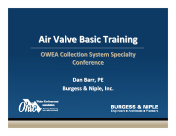
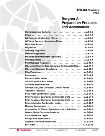
FiltersFILTER SIZINGThe flow characteristic curves should relate tothe fluid used, pressure, pipe port size andmicron rating of the filter element. Often theparameters of pressure and flow are labeled inmetric and imperial units. The vertical axis isthe pressure drop across the filter, and thehorizontal axis is the air flow through the filter.Each curved line represents the filter flow andpressure drop characteristics for differentoperating pressures.psidbar dSelecting the proper size of filter for anyapplication should be done by determining themaximum allowable pressure drop which canbe caused by the filter. The pressure drop canbe determined by referring to flow curvesprovided by the manufacturer.Flow 1)90(6.2120 150 180(8.3) (10.4) (12.5)45Pressure Drop1.64035306542520315210050100204001020603080 100 120 140 160 180 200 220 scfm405060708090 100dm 3/sAir FlowExample Find the pressure drop across thefilter when operating at 90 psig (6.2 bar) andwhen 50 scfm (24 dm3/s) is flowing throughthe filter.Answer Locate 50 scfm (24 dm3/s) on thehorizontal axis. Read up to the intersectingpoint on the 90 psig (6.2 bar)operating curve.The pressure drop (or p) is approximately .6psid (.04bar) on the vertical axis on the left ofthe graph. (See graph)1.7MEMBRANE DRYERSFor those applications where a low-pressuredewpoint and low installation/operational costare required, Norgren provides an Excelon Membrane Dryer. This new product canprovide dewpoint suppression up to 800F(260C) below ambient temperature and isavailable with nominal flows of 2, 5, 10, 20,and 30 scfm.The Membrane Dryer is a variable dew pointsuppression device constructed of an anodizedaluminum body with end caps. Inside thebody are bundles of special hollow fibers(membranes) which are semi-permeable.Moisture-laden air enters the fibers and watervapor permeates through the walls to theoutside of the fibers. Dry air exits the devicethrough the outlet port. A small percentage ofdry air is diverted across the outside of thefibers to sweep away and vent water vapor toatmosphere.Littleton, CO USAThis device provides variable dew pointsuppression inversely related to flow. Lowerflows through a unit will increase contact timewith the membrane fibers, resulting in greaterdew point suppression. Higher flows willresult in a decreased level of dew pointsuppression. Additionally, dew pointsuppression is directly related to operatingpressure. Increasing the pressure applied willresult in a greater level of dew pointsuppression. Therefore, it is alwaysrecommend placing regulators downstream ofa membrane dryer to ensure the highestpressure possible through the membrane dryer.Typical Flows for Membrane DW74M4ANNNEPort OutletFlow1/4" 2 scfm1/4" 5 scfm1/4" 10 scfm1/2" 20 scfm1/2" 30 scfmPhone 303-794-2611InletFlow2.2 scfm5.6 scfm11.2 scfm22.2 scfm33.4 scfmPurgeFlow0.2 scfm0.6 scfm1.2 scfm2.2 scfm3.4 scfmFax 303-795-9487Press.Drop0.4 psid0.32 psid0.90 psid0.65 psid1.35 psidALE-1-E
Filters1.7SIMPLE FILTER TROUBLESHOOTINGMalfunctionPossible causeRemedyExcessive pressure drop.Micron rating of element to smallUse larger micron element size for application.Filter element blocked.1. Clean element (notcoalescing element). Note: Some residualcontamination will remain.2. Replace with new element.Flow requirement greater thanfilter capacity.Use larger filter.Element seals missing ordefective. (N.B. Seals notrequired on some units).Replace seal2. Tighten element.Damaged element.Replace element.Water level in bowl abovebaffle.Drain water.Flow capacity of filterexceeded.Maintain flow within capacityof filter or change to filtercapable of handling desired flows.Bowl has been cleaned withincompatible fluid.Replace bowl.(Clean only in clean warm water and soap.)Bowl is being used in an areacontaining fumes or vaporsincompatible with polycarbonate.Replace bowl.Eliminate source of problem orconvert from plastic to metal bowls.Compressor oil vapor may becausing problem.Replace bowl.Eliminate source of problem orconvert from plastic to metal bowls.Air intake to compressor maycontain fumes or vaporReplace bowl.Eliminate source of problem orincompatible with polycarbonate.convert fromplastic to metal bowls.Inlet air has a high temperatureand as it cools downstream,moisture condenses to water.Fit dryer, pre-cool air or fitfilter immediately prior to application.Dirt passing through filter.Water passing through filter.Crazing of Polycarbonate bowlor milky appearance.Water beyond the filterALE-1-FLittleton, CO USAPhone 303-794-2611Fax 303-795-9487
Rating Filter Elements and ISO Standard 8573-1Absence of an Industrial Standard for RatingPneumatic Filter ElementsISO Standard 8573-1. Compressed Airfor General UseThere is not an industry wide standard for establishing the micronrating of pneumatic filter elements. Standards by various industryassociations, including the National Fluid Power Association(NFPA) and International Standard Organization (ISO), are indiscussion. In the absence of an industry standard, somemanufacturers of pneumatic filters make claims concerning themicron rating of their so called “standard” element which can notbe substantiated and are probably not valid.Contaminant’s found in industrial compressedair systems include solid particles, water, andoil. ISO 8573-1:1991 provides a simple methodof classifying these contaminant’s. A qualityclass required for a particular application canbe defined by listing, in order, the classrequired for solids, water, and oil.Table 1. Summary of ISO 8573-1:1991 AirQuality Classes *Norgren’s Method of Rating and TestingPneumatic Filter ElementsSolidParticleWaterNorgren particle removal filter elements are rated by the size ofthe particle they will trap (i.e., a 40-micron element will removeparticles 40-microns and larger). Norgren tests filter elements byusing standard coarse and fine test dusts of known particle sizedistribution. Coarse dust consists of 12% particles smaller than5-microns; fine grain dust consists of 39% particles smaller than5-microns. Test results show that a Norgren filter element rated at40-microns actually removes over 98% of particles 5-microns andlarger.Qua
1.2.2 Air Classes for Norgren Filters: Particulate filters condition compressed air to different degrees, dependent on the micron rating of the filter. The finer filter, 5 µm, will achieve ISO 8573 class 3.7. or class 3. Applying a 40 µm filter will. Littleton, CO USA Phone 303-794-2611 Fax 303-795-9487. 0