Transcription
INSTALLATION AND USE INSTRUCTIONSCHAIN ACTUATOR FORWINDOW AUTOMATIONACK5PATENTEDCOD. 0P5018VER.0.0REV.05.17BEFORE INSTALLING AND USING THE ACTUATOR, IT ISCOMPULSORY FOR THE INSTALLER AND THE USER TO READAND UNDERSTAND THIS MANUAL IN ALL ITS PARTS.THIS MANUAL IS INTEGRAL PART OF THE ACTUATORAND MUST BE PRESERVED FOR FUTURE REFERENCEUNTIL DEMOLITION OF THE SAME.
ACK5INDEX1- EC DECLARATION OF INCORPORATION OF PARTLY COMPLETEDMACHINERY.page 042- GENERAL REMARKS2.1- General instructions .page 052.2- Installer and user .page 052.3- Warranty .page 052.4- Technical assistance .page 052.5- Reserved rights .page 052.6- Description of personnel .page 063- TECHNICAL DESCRIPTION3.1- Rating plate and "CE" marking .page 073.2- Denomination of the components and dimensions.page 083.3- Technical data .page 093.4- Formulas for the calculation of thrust force or tractive force.page 103.5- Destination of use .page 103.6- Use Limits.page 113.7- Package.page 114- SAFETY4.1- General instructions .page 134.2- Safety devices .page 134.2.1- Protections against electric hazard .page 134.3- Safety plates.page 144.4- Residual risks .page 145- INSTALLATION5.1- General instructions .page 155.2- Top hung windows.page 165.3- Bottom hung windows .page 175.4- Electric connections .page 195.5- Control devices.page 195.6- Window closing adjustment.page 205.7- Emergency procedures .page 216- USE AND OPERATION6.1- Use of the actuator.page 227- MAINTENANCE7.1- General instructions .page 238- DEMOLITION8.1- General instructions .page 249- SPARE PARTS AND ACCESSORIES UPON REQUEST9.1- General instructions .page 24FIGURES.page 28INSTALLATION AND USE ISTRUCTIONS3
1- EC DECLARATION OF INCORPORATION OF PARTLY COMPLETED MACHINERYACK5ORIGINALThe undersigned, in the name of and behalf of the following companyTopp S.r.l.Via Galvani, 5936066 Sandrigo (VI)Italiaherewith declaresthat the person authorised to compile the technical file isName:Bettiati Roberto - Topp S.r.l.Address: via Galvani,59 36066 Sandrigo (VI)andthat to the partly completed machineryCHAIN ACTUATOR FOR WINDOW AUTOMATIONType:Model(s):ACK5ACK5/230V - ACK5/24Vthe following essential requirements of the following EC directive (including all applicableamendments)2006/42/EC Machinery Directive (Italian adoption DLgs 27 jan. 2010, n.17)have been applied and fulfilled:Enclosure I: 1.5.1; 1.5.2; 1.5.10; 1.5.11and that the relevant technical documentation is compiled in accordance with part B ofAnnex VII of the above mentioned Machinery Directive.The above identified partly completed machinery is also in conformity with the all therelevant provisions of the following EC directives (including all applicable amendments)2014/30/EU EMC Directive2011/65/EU ROHS II DirectiveThe following harmonised standards have been applied:EN 55014-1EN 55014-2EN 61000-3-2EN 61000-3-3EN 61000-6-2EN 61000-6-3EN 62233EN 50581EN 60335-1Applicable parts of EN 60335-2-103The undersigned also undertakes the obligation, in response to a duly reasoned request by thenational market surveillance authorities, to transmit to the a.m. authorities, in electronic orpaper format, the relevant technical documentation on the partly completed machinery.The above identified partly completed machinery must not be put into service until the finalmachinery into which it is to be incorporated has been declared in conformity with theprovisions of the above mentioned Machinery Directive.This declaration of conformity is issued under the sole responsibility of the manufacturer and isvalid for products built from the date specified below.Date: Sandrigo, 01/05/20174Signature: Matteo CavalcanteAdministrator .INSTALLATION AND USE ISTRUCTIONS
ACK5GENERAL REMARKS -22.1- GENERAL INSTRUCTIONSBEFORE INSTALLING AND USING THE ACTUATOR, IT IS COMPULSORY THAT THEINSTALLER AND THE USER CAREFULLY READ AND UNDERSTAND THIS MANUAL INALL ITS PARTS.THIS MANUAL IS INTEGRAL PART OF THE ACTUATOR AND MUST COMPULSORILY BEPRESERVED FOR FUTURE REFERENCE.THE MANUFACTURER HAS NO LIABILITY FOR ANY EVENTUAL DAMAGE TO PERSONS,ANIMALS AND THINGS DUE TO THE INOBSERVANCE OF THE PRESCRIPTIONSDESCRIBED IN THIS MANUAL.THE WARRANTY ON THE ACTUATOR WILL NOT BE HONORED IF PRODUCT IS NOTINSTALLED AND USED ACCORDING TO THE INSTRUCTIONS PROVIDED AND THEREGULATIONS SHOWN IN THIS INSTRUCTION MANUAL AND IF IT IS USED WITH NONGENUINE PARTS, ACCESSORIES, SPARE PARTS AND/OR CONTROL/FEEDING UNITS.2.2- INSTALLER AND USERTHE ACTUATOR INSTALLATION CAN BE PERFORMED EXCLUSIVELY BY COMPETENTAND QUALIFIED TECHNICAL PERSONNEL SATISFYING THE PROFESSIONAL ANDTECHNICAL REQUIREMENTS FORESEEN BY THE LAWS IN FORCE IN THE COUNTRY OFINSTALLATION.THE ACTUATOR CAN BE USED EXCLUSIVELY BY A USER ACTING IN COMPLIANCE WITHTHE INSTRUCTIONS CONTAINED IN THIS MANUAL AND/OR IN THE MANUAL OF THEACTUATOR CONTROL DEVICE (e.g.: CONTROL UNIT).2.3- WARRANTYTHE ACTUATOR WARRANTY EXPIRES, IF ITS USE DOES NOT COMPLY WITH THEINSTRUCTIONS AND PRESCRIPTIONS DESCRIBED IN THIS MANUAL, AS WELL AS IFNON-ORIGINAL COMPONENTS, ACCESSORIES, SPARE PARTS, AND CONTROLSYSTEMS ARE USED (SEE LAST PAGE).2.4- TECHNICAL ASSISTANCEFor the technical assistance apply to your Dealer or to the Manufacturer.2.5- RESERVED RIGHTSThe reserved rights on this manual "Installation and use instructions" remainproperty of the Manufacturer.Each information herein contained (text, drawings, diagrams, etc.) is reserved.None part of this manual can be reproduced and disclosed (totally or partially) by anyreproduction means (photocopies, microfilms or other) without written authorization ofthe Manufacturer.INSTALLATION AND USE ISTRUCTIONS5
2- GENERAL REMARKSACK52.6- DESCRIPTION OF PERSONNELUSERS MUST NEVER PERFORM OPERATIONS RESERVED FOR MAINTENANCEPEOPLE OR SPECIALISED TECHNICIANS. THE MANUFACTURER DECLINES ALLLIABILITY FOR DAMAGE DERIVING FROM FAILURE TO OBSERVE THE ABOVEREQUIREMENTS.Specialised electrician:A specialised electrician must be able to install the actuator, start it and operate it bothin normal conditions and in the maintenance mode; he/she is qualified to perform allelectrical and mechanical adjustment and maintenance operations. He/she is allowedto work on live electrical cabinets and junction boxes.User:specialised person capable of operating the actuator under normal conditions by usingthe relative controls. He/she must also be able to operate with the actuator under“maintenance” in order to perform simple routine maintenance operations (cleaning),and start or reset the actuator following an unscheduled stop.6INSTALLATION AND USE ISTRUCTIONS
ACK5TECHNICAL DESCRIPTION -33.1- RATING PLATE AND "CE" MARKINGThe "CE" marking certifies the compliance of the machine with the essential safety andhealth requirements foreseen by the product European Directives.The rating plate is an adhesive plate in polyester, silk-screen printed in black, having thefollowing size: L 50 mm - H 36 mm.It is applied externally on the actuator. The plate bears in readable and indelible way thefollowing data: logo and address of the manufacturer type and model voltage and intensity of power supply (V - A) absorbed electric power P (W) thrust and tractive force F (N) type of service S2(min) idle translation speed (mm/s) protection degree (IP) "CE" marking symbol of “WEEE” Directive 2002/96/CE symbol of double insulation (only for mod. ACK5/230V) serial numberINSTALLATION AND USE ISTRUCTIONS7
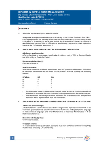
3- TECHNICAL DESCRIPTIONACK53.2- DENOMINATION OF THE COMPONENTS AND DIMENSIONSFig. 2 Dimensions in mm12345678LEGEND:1) Power supply cable2) Support heads3) Support4) Opening stroke adjustment on both sides5) Actuator6) Chain pin7) Bracket for bottom hung opening8) Window frame connection bracket8INSTALLATION AND USE ISTRUCTIONS
TECHNICAL DESCRIPTION -3ACK53.3- TECHNICAL DATATab. 1 contains the technical data characterising the actuators.Power supply voltageACK5/230VACK5/24V230 V - 50 Hz24 VAbsorbed current0,32 A1,35 AAbsorbed power with load75 W32 WThrust force300 NTractive force300 NIdle translation speed27 mm/s17 mm/sDuration of idle stroke15 s23 sTop hung windowH 600 mmBottom hung windowH 800 mmMinimum window frame height (1)Adjustable stroke end(2)10 - 15 - 20 - 25 - 30 - 35 - 40 cmElectronics with warning horn to signal to the user the wrong assembling (3)Protection against electric shocksType of service S2(4)Operating temperatureClass IIClass III2 min3 min- 5 ºC 50 ºCProtection degree of electric devicesIP 55Adjustment of the window frame connection10 mmParallel electric connection of moreactuators on the same windowOnly with properelectronic deviceParallel electric connection of moreactuators on different windowsYes(see wiring diagram)Actuator weight with brackets1,7 kgGross weight1,9 kg(1)Actuator distance from the window frame opening hingeTolerance on the precision of the output limit switch tripping: /- 1 cm(3)The "buzzer" device is enabled automatically and emits a continuous "beep" as long as theactuator is fed. For further details on its operation see par. 5.6(4)Service of limited duration according to EN 60034(2)Tab. 1INSTALLATION AND USE ISTRUCTIONS9
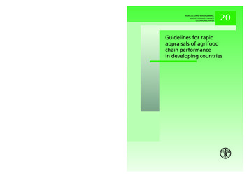
3- TECHNICAL DESCRIPTIONACK53.4- FORMULAS FOR THE CALCULATION OF THRUST AND TRACTIVEFORCEFig. 3Horizontal domes or skylightsFF(N) Force necessary for opening orclosingP(N) Weight of the skylight or dome(Only movable part)PF 0,54 x PFig. 4BCFF (0,54 x P) x ( C )HHF(N) Force necessary for opening orclosingP(N) Weight of the window(only movable part)C(mm) Window opening strokeH(mm) Window heightAHTop hung windows (A) orbottom hung windows (B)PPFC3.5- DESTINATION OF USETHE ACTUATOR HAS BEEN DESIGNED AND MANUFACTURED TO PERFORMAUTOMATICALLY, BY MEANS OF A CONTROL DEVICE, THE OPENING AND CLOSING OFTOP HUNG WINDOWS, BOTTOM HUNG WINDOWS, PIVOT WINDOWS, AND SKYLIGHTS.10INSTALLATION AND USE ISTRUCTIONS
ACK5TECHNICAL DESCRIPTION -33.6- USE LIMITSThe actuator has been designed and manufactured exclusively for the destination ofuse given in par .3.5, therefore, any other type of use is strictly forbidden in order toassure in any moment the safety of the installer and of the user, as well as theefficiency of the actuator itself.Check carefully all environmental conditions (temperature, humidity, wind, snow,potential chemical agents, etc.) and installation settings (misaligned fitting of bracketsand attachment to the frame, frictions produced by hinges or gaskets, use of selfbalancing window stays, etc.) it is recommended that they not exceed the actuatorperformances shown in the technical table, Tab1. If they do, please find an alternativeand more suitable product for your application.IT IS STRICTLY FORBIDDEN TO USE THE ACTUATOR FOR IMPROPER USES OTHERTHAN THE ONE FORESEEN BY THE MANUFACTURER (SEE PAR. 3.5).IT IS STRICTLY FORBIDDEN TO INSTALL THE ACTUATOR ON THE EXTERNAL SIDE OFTHE WINDOW FRAME SUBJECT TO ATMOSPHERIC AGENTS (RAIN, SNOW, ETC.).EXTHE USE OF THE ACTUATOR IN ENVIRONMENTS WITH POTENTIALLY EXPLOSIVEATMOSPHERE IS STRICTLY FORBIDDEN.IT IS COMPULSORY TO KEEP THE PACKAGE AND THE ACTUATOR OUT OF REACH OFCHILDREN.3.7- PACKAGEEach standard package of the product (cardboard box) contains (Fig. 5): No. 1 Actuator equipped with power supply cable (Ref.A);Ÿ No. 1 Small parts package (window connection bracket, nuts, pin and fasteningscrews for aluminium window frames) (Ref. B); No. 1 Adhesive drilling template (Ref. C); No. 1 Installation and use instructions (Ref. D); No.1 Safety Plate (Fig. 6).MAKE SURE THAT THE ABOVE DESCRIBED COMPONENTS ARE CONTAINED IN THEPACKAGE, AS WELL AS THAT THE ACTUATOR HAS NOT BEEN DAMAGED DURINGTRANSPORT.SHOULD ANY ANOMALY BE DETECTED, IT IS FORBIDDEN TO INSTALL THE ACTUATOR,AND IT IS COMPULSORY TO REQUIRE TECHNICAL ASSISTANCE FROM YOUR DEALEROR THE MANUFACTURER.THE PACKAGING (PAPER, PLASTIC, ETC.) HAS TO BE DISPOSED ACCORDING TO THELAWS IN FORCE.INSTALLATION AND USE ISTRUCTIONS11
3- TECHNICAL TPEIONR L’INANSTD ALUSLAE INSZIOTRNEUCE TIOL'UNSSOATTUCHATAINOREACAUWIA TUTONDCAATMAOWTEORZIOAUNA FONETOPERFINMAESTIOTRNEACK5BREENTPATVETEDTATOPRIMA DI INSTBEFOREL’INSALLACOMCODTALLP/N .0PRE EINSTPULATO0P5000SORREUTILALLIIN TUTTANDY FORIZZAE L’UTNGREV.ANDUNDERSREUSINE LETHEILIZZL’ATTUA05/03REVINSTATORESUE PARTANG THE.SENTETORD THISTI ALLELEGTHISMANEÈACTIL PRERANDGANOMANOBBLIGAUATMANPER FUTUUALANDOBBTHEEUSEUALSENUALE ISPARCOMOR,MUSLIGAIT ISIN TETORALLMANRI RIFET BE ÈR PREINTETETO REAITSUALNDANOIO CHEGRAPREINTEIAMERIMETORPARE.UNTSERNTEL PARDGRANTETS.ILNTIVEDESSDEMT OF DELFINOFOREREOLITALLATHE L’ATFUTUION OFCONACTTUADEMRESERUATTORTHEOLIZREFVATOOR E EIONESAMERENCEDEVEE. DELLO STESSO.IL PRED12INSTALLATION AND USE ISTRUCTIONS
ACK5SAFETY -44.1- GENERAL INSTRUCTIONSOPERATORS MUST BE INFORMED OF ACCIDENT RISKS, SAFETY DEVICES AND THEGENERAL ACCIDENT PREVENTION REGULATIONS ESTABLISHED BY INTERNATIONALDIRECTIVES AND BY THE LAW IN FORCE IN THE COUNTRY OF USE.ALL OPERATORS MUST STRICTLY COMPLY WITH THE ACCIDENT PREVENTIONREGULATIONS IN FORCE IN THE COUNTRY OF USE.DO NOT REMOVE OR ALTER THE PLATES PLACED ON THE ACTUATOR BY THEMANUFACTURER.IF THE WINDOW FRAME IS ACCESSIBLE FROM OR INSTALLED AT A HEIGHT OF LESSTHAN 2.5 m FROM THE GROUND, AND IF IT CAN BE COMMANDED BY AN UNTRAINEDUSER OR WITH A REMOTE CONTROL DEVICE, FIT AN EMERGENCY STOP SYSTEMWHICH AUTOMATICALLY CUTS IN TO PREVENT THE RISK OF CRUSHING ORDRAGGING PARTS OF THE BODY INSERTED BETWEEN THE MOVING AND FIXED PARTSOF THE WINDOW FRAME.ANY TAMPERING WITH OR UNAUTHORISED REPLACEMENT OF ONE OR MORE PARTSOR COMPONENTS OF THE ACTUATOR, OR THE USE OF UNORIGINAL ACCESSORIESAND CONSUMABLES, MAY INCREASE THE RISK OF ACCIDENT AND THUS RELIEVESTHE MANUFACTURER OF ALL CIVIL AND PENAL LIABILITYEXTRAORDINARY AND ROUTINE MAINTENANCE OPERATIONS INVOLVING THE TOTALOR PARTIAL DISMOUNTING OF THE ACTUATOR MAY ONLY BE PERFORMED AFTERDISCONNECTING IT FROM THE POWER SUPPLY.THIS APPLIANCE MAY NOT BE USED BY PERSONS (CHILDREN INCLUDED) WITHREDUCED PHYSICAL, SENSORIAL OR MENTAL CAPACITIES, OR INEXPERT PEOPLE,UNLESS THEY ARE SUPERVISED AND TAUGHT HOW TO USE IT BY A PERSONRESPONSIBLE FOR THEIR SAFETY. CHILDREN MUST BE CONTROLLED TO MAKESURE THEY DO NOT PLAY WITH THE APPLIANCE.4.2- SAFETY DEVICES4.2.1- PROTECTION AGAINST ELECTRIC HAZARDThe actuator is protected against electric hazard due to direct and indirect contacts.The protection measures against direct contacts aim at protecting people againsthazards due to contact with active parts, usually live parts; while the protectionmeasures against indirect contacts aim at protecting people against hazards due toconducing part, which are usually insulated, but could become live in case of failure(insulation failure).The adopted protection measures are the following:1) Insulation of live parts by means of a plastic material body;2) Enclosure with suitable protection degree;INSTALLATION AND USE ISTRUCTIONS13
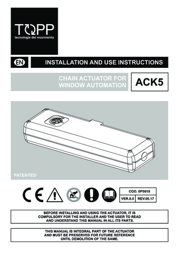
4- SAFETYACK53) Only for the mod. ACK5/230V provided with protection against electric shocks:Protection of passive type given by the use of components with double insulation,also called components of class II or with equivalent insulation.4.3- SAFETY PLATESIT IS FORBIDDEN TO REMOVE, MOVE, SPOIL OR IN ANYWAY REDUCE THE VISIBILITYOF THE SAFETY PLATES. FAILURE TO OBSERVE THE ABOVE MAY CAUSE SERIOUSHARM TO PEOPLE AND DAMAGE TO PROPERTY. THE MANUFACTURER DECLINES ALLLIABILITY FOR ANY DAMAGE CAUSED BY THE FAILURE TO OBSERVE THE ABOVEREQUIREMENT.Fig. 6 illustrates the safety plate: this must applied directly to the outside of the actuatoror near it and always in a position where it can be seen by the installer and/or operator.4.4- RESIDUAL RISKSThe installer and the user are herewith informed that after the actuator has beeninstalled on the window, the actuator drive can accidentally generate the followingresidual risk:Residual risk:Hazard of squashing or dragging of body parts inserted between themovable and the fix part of the window frame.Exposure frequency: Accidental and when the installer or the user decides to performa wrong voluntary action.Severity of the damage:Light lesions (usually reversible).Adopted measures:Before enabling the device, it is compulsory to verify that near thewindow there are not persons, animals or things whose safety may be accidentallyjeopardized. During actuator operation, it is compulsory to be in a safe control positionassuring visual control on the window movement (see par. 6.1).Fig. 6MACCHINA AD AVVIAMENTO AUTOMATICOAUTOMATIC MACHINEPRIMA DI INSTALLARE E UTILIZZARE L'ATTUATORE È OBBLIGATORIO CHE L'INSTALLATORE E L'UTILIZZATORELEGGANO E COMPRENDANO IN TUTTE LE SUE PARTI IL MANUALETHE INSTALLER AND USER MUST READ AND UNDERSTAND ALL PARTS OF THIS MANUAL BEFORE INSTALLINGAND USING THE ACTUATOR.PERICOLO ATTENZIONE ALLE MANIBEWARE OF YOUR HANDSATTENZIONE MACCHINA AD AVVIAMENTO AUTOMATICO CON COMANDO A DISTANZAATTENTION! AUTOMATIC MACHINE WITH REMOTE CONTROL DEVICE14INSTALLATION AND USE ISTRUCTIONSITEN
INSTALLATION -5ACK55.1- GENERAL INSTRUCTIONSTHE ACTUATOR INSTALLATION CAN BE PERFORMED EXCLUSIVELY BY COMPETENTAND QUALIFIED TECHNICAL PERSONNEL SATISFYING THE PROFESSIONAL ANDTECHNICAL REQUIREMENTS FORESEEN BY THE LAWS IN FORCE IN THE COUNTRY OFINSTALLATION.THE ACTUATOR PERFORMANCE MUST BE SUFFICIENT TO ASSURE THE CORRECTMOVEMENT OF THE WINDOW. IT IS COMPULSORY TO VERIFY THE THRUST ORTRACTIVE FORCE ACCORDING TO THE TYPE AND WEIGHT OF THE WINDOW (PAR. 3.4).IT IS FORBIDDEN TO EXCEED THE LIMITS GIVEN IN TAB. 1 CONCERNING THETECHNICAL DATA (PAR. 3.3).THE ACTUATOR INSTALLATION MUST BE PERFORMED EXCLUSIVELY WITH CLOSEDWINDOW OR SKYLIGHT.BEFORE PERFORMING THE INSTALLATION OF THE ACTUATOR ON HOPPERWINDOWS, VERIFY THAT ON BOTH SIDES OF THE WINDOW TWO COMPASS STROKELIMIT DEVICES ARE INSTALLED IN ORDER TO AVOID THE ACCIDENTAL FALL OF THEWINDOW.FOR CORRECT OPERATION OF THE ACTUATOR, THE WINDOW MUST HAVE A MINIMUMHEIGHT OF 800 mm (DISTANCE OF THE ACTUATOR FROM THE WINDOW OPENINGHINGE). OTHERWISE, ASK YOUR DEALER OR THE MANUFACTURER FOR THENECESSARY ACCESSORIES FOR A CORRECT INSTALLATION.VERIFY THAT THE DISTANCE "D" BETWEEN THE FIXED PART OF THE WINDOW (ONWHICH THE FIXING OF THE ACTUATOR IS FORESEEN - FIG. 7 - REF. 1) AND THEMOVABLE PART OF THE WINDOW (ON WHICH THE BRACKET FIXING IS FORESEEN FIG. 7 - REF. 2) IS INCLUDED WITHIN 0 AND 10 mm. OTHERWISE, ASK YOUR DEALER ORTHE MANUFACTURER FOR THE NECESSARY ACCESSORIES FOR A CORRECTINSTALLATION (SEE CHAP. 9)Fig. 7D 0 10 mm21INSTALLATION AND USE ISTRUCTIONS15
5- IINSTALLATIONACK55.2- TOP HUNG WINDOWS(Fig. 8 and 16 26)Fig. 81) Open the package (par. 3.7) and extract thevarious components;2) Fig. 17- With a pencil draw the centre line "X" ofthe window frame;3) Fig. 18- Select the following components:bracket "S1", support "SA", two nuts "D1", twoscrews "V1", heads "T1" and “T2";4) Fig. 19- Insert the two nuts "D1" on the support"SA" and mount the head "T1" by fixing it usingscrew "V1";5) Fig. 20- Cut out the adhesive template "DS" and apply it on the window framecentring it on the previously drawn centre line "X";CAUTION: FOR NON-COPLANAR WINDOW FRAMES, IT IS NECESSARY TO CUT THETEMPLATE CONCERNED PART AND TO APPLY IT ON THE WINDOW FRAME PAYINGATTENTION TO KEEP IT IN THE SAME REFERENCE POSITION.6) With a suitable drill, create on the window frame holes having the related diameter,given on the adhesive template "DS";7) Fig. 21- Mount the support "SA" on the fix window frame with the screws "V2"; Checkthe perfect horizontal and vertical alignment with the window frame;8) Fig. 22- Mount the bracket "S1" on the movable window frame with the screws "V2";9) Mount the actuator on the support "SA", place the head "T2" and tighten the screw "V1;VERIFY THAT THE CHAIN END "TC" IS ON THE SAME AXIS OF THE BRACKET "S1".OTHERWISE, LOOSEN THE FIXING SCREWS AND POSITION IT CORRECTLY. WHEN THEDEVICES ARE NOT COAXIAL, THIS MAY DAMAGE THE ACTUATOR AND THE WINDOWFRAME (FIG. 9).Fig. 9YESNOTC16S1INSTALLATION AND USE ISTRUCTIONSTCS1
INSTALLATION -5ACK510) Fig. 23- Mount the nut "D2" on the screw "V3" and then it on the chain ending "TC";Fig. 24- Connect the bracket "S1" to the screw "V3" by means of the pin "P";11) Perform the electric connections according to the prescriptions of par. 5.4, as wellas with reference to the wiring diagram;12) Fig. 25- Act with a screwdriver or with a coin on the adjustment screw "VR", settingthe wished opening stroke (cm);CAUTION: VERIFY THAT THE SELECTED STROKE IS SOME CENTIMETRES LOWERTHAN THE STROKE EFFECTIVELY ALLOWED BY MECHANICAL LOCKS, COMPASSSTROKE LIMIT DEVICES, OR WING OPENING HINDRANCES.13) Fig. 26- Perform a test of complete window frame opening and closing. After theclosing phase, verify that the chain end "TC" is completely returned in its seat(Ref. A);14) If the closing is right (Ref. A), fix the screw "V3" with the nut "D2" and the pin "P".If the closing is not precise (Ref. B), perform the necessary adjustment of the screw"V3" and of the nut "D2".FOR A CORRECT ADJUSTMENT OF THE WINDOW FRAME CLOSING SEE THEINDICATIONS GIVEN IN PAR. 5.6.5.3- BOTTOM HUNG WINDOWS(Fig. 10 and 27 37)Fig. 101) Open the package (par. 3.7) and extract thevarious components;2) Fig. 28- With a pencil draw the centre line "Y" ofthe window frame;3) Fig. 29- Select the following components:bracket "S2" and "S3", support "SA", two nuts"D1", two screws "V1", screw "V4", heads "T1"and "T2";4) Fig. 30- Insert the two nuts "D1" on the support"SA" and mount the head "T2" by fixing it using screw "V1";5) Fig. 31- Cut out the adhesive template "DV" and apply it on the window framecentring it on the previously drawn centre line "Y";CAUTION: FOR NON-COPLANAR WINDOW FRAMES, IT IS NECESSARY TO CUT THETEMPLATE CONCERNED PART AND TO APPLY IT ON THE WINDOW FRAME PAYINGATTENTION TO KEEP IT IN THE SAME REFERENCE POSITION.INSTALLATION AND USE ISTRUCTIONS17
5- INSTALLATIONACK56) With a suitable drill, create on the window frame holes given on the adhesivetemplate "DV";7) Fig. 32- Mount the support "SA" on the fix window frame with the screws "V2"; checkthe perfect horizontal and vertical alignment with the window frame;8) Fig. 33- Mount the bracket "S2" on the movable window frame with the screws "V2";9) Mount the actuator on the support "SA", place the head "T1" and tighten the screw"V1;VERIFY THAT THE CHAIN END "TC" IS ON THE SAME AXIS OF THE BRACKET "S1".OTHERWISE, LOOSEN THE FIXING SCREWS AND POSITION IT CORRECTLY. WHEN THEDEVICES ARE NOT COAXIAL, THIS MAY DAMAGE THE ACTUATOR AND THE WINDOWFRAME (SEE FIG. 9).10) Fig.34- Mount the nut "D2" on the screw "V3" and then it on the chain end "TC";Fig.35- Connect the bracket "S3" to bracket "S2" and fix it with the screw "V4".Connect the bracket "S3" with the screw "V3" by means of the pin "P";11) Perform the electric connections according to the prescriptions of par. 5.4, as wellas with reference to the wiring diagram;12) Fig. 36- Act with a screwdriver or with a coin on the adjustment screw "VR", settingthe wished opening stroke (cm);CAUTION: VERIFY THAT THE SELECTED STROKE IS SOME CENTIMETRES LOWERTHAN THE STROKE EFFECTIVELY ALLOWED BY MECHANICAL LOCKS, COMPASSSTROKE LIMIT DEVICES, OR WING OPENING HINDRANCES.13) Fig. 37- Perform a test of complete window frame opening and closing. After theclosing phase, verify that the chain end "TC" is completely returned in its seat(Ref. A);14) If the closing is right (Ref. A), fix the screw "V3" with the nut "D2" and the pin "P".If the closing is not precise (Ref. B), perform the necessary adjustment of the screw"V3" and of the nut "D2". If necessary, act also on the bracket "S3", unscrewing thescrew "V4" it is possible to unhook the two brackets modifying their couplingposition.FOR A CORRECT ADJUSTMENT OF THE WINDOW FRAME CLOSING SEE THEINDICATIONS GIVEN IN PAR. 5.6.18INSTALLATION AND USE ISTRUCTIONS
INSTALLATION -5ACK55.4- ELECTRIC CONNECTIONS (Wiring diagram)THE ELECTRIC CONNECTION OF THE ACTUATOR CAN BE PERFORMED ONLY BYCOMPETENT AND QUALIFIED TECHNICAL PERSONNEL SATISFYING THE TECHNICALAND PROFESSIONAL REQUIREMENTS FORESEEN BY THE LAW IN FORCE IN THECOUNTRY OF INSTALLATION ISSUING TO THE CUSTOMER A DECLARATION OFCONFORMITY FOR THE CONNECTION AND/OR THE PLANT PERFORMED.THE ELECTRIC CONNECTION OF THE VERSION ACK5/24V HAS TO BE CARRIED OUTWITH A VERY LOW SAFETY VOLTAGE FEEDER PROTECTED AGAINST SHORTCIRCUITS.BEFORE PERFORMING THE ELECTRIC CONNECTION OF THE ACTUATOR, VERIFY THECORRECT INSTALLATION ON THE WINDOW.THE MAINS TO WHICH THE ACTUATOR IS CONNECTED MUST COMPLY WITH THEREQUIREMENTS OF THE LAWS IN FORCE IN THE COUNTRY OF INSTALLATION, ASWELL AS SATISFY THE TECHNICAL FEATURES GIVEN IN TAB. 1 AND ON THE RATINGPLATE AND THE "CE" MARKING (PAR. 3.1).THE SECTION OF THE MAINS CABLES MUST BE PROPERLY SIZED ACCORDING TO THEABSORBED ELECTRIC POWER (SEE RATING PLATE AND "CE" MARKING).ANY TYPE OF ELECTRIC MATERIAL (PLUG, CABLE, TERMINALS, ETC.) USED FOR THECONNECTION MUST BE SUITABLE FOR THE USE, WITH "CE" MARKING ANDCOMPLYING WITH THE REQUIREMENTS FORESEEN BY THE LAWS IN FORCE IN THECOUNTRY OF INSTALLATION.TO ASSURE EFFICIENT SEPARATION FROM THE MAINS, INSTALL AN APPROVEDTEMPORARY BIPOLAR SWITCH (PUSH-BUTTON) UPLINE OF THE DEVICE. FIT ABIPOLAR MAIN SWITCH WITH CONTACT APERTURE OF AT LEAST 3 mm UP LONE OFTHE CONTROL LINE.BEFORE PERFORMING THE ELECTRIC CONNECTION OF THE ACTUATOR, VERIFYTHAT THE POWER SUPPLY CABLE IS NOT DAMAGED. SHOULD IT BE DAMAGED, ITMUST BE REPLACED BY THE MANUFACTURER OR BY THE TECHNICAL ASSISTANCESERVICE OR IN ANY CASE BY AUTHORIZED OPERATORS.5.5- CONTROL DEVICESTHE CONTROL DEVICES USED TO DRIVE THE ACTUATOR MUST ASSURE THE SAFETYCONDITIONS FORESEEN BY THE LAWS IN FORCE IN THE COUNTRY OF USE.According to the different type of installations, the actuators can be driven by thefollowing control devices:1) MANUAL PUSH-BUTTON:Bipolar switch button with central OFF position, with biased-off switch;INSTALLATION AND USE ISTRUCTIONS19
5- INSTALLATIONACK52) CONTROL AND FEEDING UNIT:Microprocessor control units (e.g.: Mod. TF, etc.) controlling the single actuator ormore than one actuator simultaneously by means of one or more manual pushbuttons, an infrared remote control or a 433 Mhz radio control.To these control units, it is possible to connect the rain sensors (RDC - 12V), the windsensor (RW) and the brightness sensor;THE EVENTUALLY USED UNITS MUST SUPPLY A VOLTAGE TO ACK5 FOR MAX. 120 s.3) SYNCHRONIZATION UNIT:Microprocessor control unit (USA2) controlling by means of a manual push-buttonthe simultaneous operation of 2 actuators installed on a single window assuring theregular opening and closing movement.5.6- ADJUSTMENT OF THE WINDOW FRAME CLOSING (Fig. 25-35)THE CORRECT ADJUSTMENT OF THE WINDOW FRAME CLOSING ASSURES THE LIFEAND THE TIGHTNESS OF THE SEALS, AS WELL AS THE GOOD OPERATION OF THEACTUATOR.A good method to perform the adjustment is to let the chain go back without load into theactuator and, then, to measure the position of the chain ending with reference to theexternal casings.Then, tighten the window frame fixing screw and let the chain go back.The adjustment is right, when with closed window the chain ending has the sameposition detected during the test without load.As given in Fig. 26 -
TOP HUNG WINDOWS, BOTTOM HUNG WINDOWS, PIVOT WINDOWS, AND SKYLIGHTS. 3.4- FORMULAS FOR THE CALCULATION OF THRUST AND TRACTIVE FORCE Top hung windows (A) or bottom hung windows (B) F (N) Force necessary for opening or closing P (N) Weight of the window (only movable part) C (mm) Window opening stroke H (mm) Window height F (0,54 x P) x .