Transcription
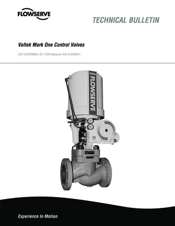
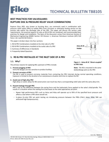
TECHNICAL BULLETIN TB8105BEST PRACTICES FOR VALVEGUARD:RUPTURE DISC & PRESSURE RELIEF VALVE COMBINATIONSRupture Discs (RD), also known as bursting discs, are commonly used in combination withpressure relief valves (PRV) to isolate PRVs from corrosive or otherwise fouling service on theprocess side and/or the discharge side of the PRV. This paper will discuss the various coderequirements, the practical aspects for why an RD & PRV are combined, and recommended bestpractices for design and installation. The basis of the discussion comes from American Society ofMechanical Engineering (ASME) Section VIII Division 1, American Petroleum Institute (API) 520Parts 1 & 2 and EN ISO 4126‐3.This paper is broken down into four sections:1. RD & PRV Combinations installed at the inlet side of a PRV2. RD & PRV Combinations installed at the outlet side of a PRV3. Summary of differences in Standards4. Frequently Asked QuestionsAxius & XLHolder1. RD & PRV INSTALLED AT THE INLET SIDE OF A PRV1.1. Why?The primary reasons for applying RDs upstream of PRVs include:Figure 1 – Axius & XL "direct‐coupled"to PRV inlet.1. Prevent plugging of PRVSome RD designs are less sensitive to product buildup.Note: The RD is mounted in the samebolted flange joint as the PRV.2. Prevent corrosion of PRVThe RD is used to prevent corrosive materials from contacting the PRV internals during normal operating conditions.Exposure is limited to the duration of an overpressure situation and time to replace the RD.3. Avoid cost of high alloy PRVHigh alloys or exotic alloys for RD construction cost much less than a corresponding relief valve with the same alloy trim.4. Prevent leakage through PRVPRV’s rely on the difference between the spring force and the hydrostatic force applied to the valve’s disk/spindle. Thisresults in a situation where the sealing force decreases as the valve approaches set point. Newer high performance RD's such as Axius and Atlas will operate up to 95% of the specified burst pressure andaffects a seal where a PRV alone would not. In‐place (In‐situ) PRV set point testing via introducing pressure between the PRDs (Fike’s Axius, Atlas, SRX canwithstand high backpressures).704 SW 10th Street, P.O. Box 610, Blue Springs, Missouri 64013‐0610 U.S.A.Phone: (816) 229‐3405 www.fike.comForm No. TB8105‐01 of 10
1.2. How?When installing a RD between a pressure vessel and PRV, the following requirements must be met:1.2.1. Non‐FragmentingThe RD used on the inlet side of a PRV must be a non‐fragmenting design. The RD must not eject material that can impairPRV performance. This includes relief capacity as well as the ability to reclose without leakage. Refer to section 1.2.4 formore information about single petal RD types.1.2.2. Monitoring (tell‐tale indicator)The RD is a differential pressure device. If any back pressure accumulates between the RD and PRV, the pressure in thevessel required to burst the RD will increase in proportion. Therefore, the space between the RD and PRV must be ventedand monitored to prevent/detect pressure buildup between the RD and the PRV. The ASME and EN Pressure Vessel Codesrequire the use of a pressure gauge, a try cock, free vent, or suitable telltale indicator.If the space between the RD and PRV is otherwise closed, then a pressure gauge alone should not be considered suitable.This approach relies on plant personnel to periodically check each gauge to insure that pressure buildup has not occurred.This could easily result in an unsafe situation existing for hours, days or weeks at a time. A pressure switch or transmitterthat provides an alarm in the control room is a more appropriate indication method. If the space between the RD and PRVis closed and does not feature a free vent, consideration should be given to using a high integrity pressure transmitter(such as Emerson Rosemount or equivalent). A pressure gauge along with a pressure switch or transmitter may be an evenbetter choice so not only the control room is notified, but the maintenance personnel also have visibility to the elevatedpressure condition prior to breaking loose the pipe flanges. This requires the holder to feature multiple gauge taps and/orpiping manifolds.In some cases, the space between the RD and PRV is not vented, but venting to atmosphere, a catch tank, or aflare/collection header may be desired. It is common in these cases to use an excess flow valve (a type of check valve) onthe venting line. At very low flow conditions, as in the case of thermal expansion of trapped air, the check ball allows thefluid to vent. When the RD ruptures, the excess flow valve closes to restrict and minimize fluid loss through the vent.No one configuration is ideal for all applications. The corrosiveness or toxicity of the media is often what drives how thisspace is monitored, and how the pressure and effluent vented. The RD holders available by Fike feature gauge taps for thispurpose, or the tell‐tale indication can be located in the downstream spacer or spool piece between the RD & PRV.Note: Break wire or other flow sensitive burst indication devices (Such as the Fike BC2) are not considered suitable for thisfunction unless they are capable of detecting leakage through the RD.1.2.3. CapacityThe rupture disc capacity must be equal to or greater than relief area of the PRV. This generally means that the RD has tobe the same nominal pipe size, or larger, than the PRV inlet. This is easily validated if the PRV and RD have been tested,and the CCCF values are listed; a summary of these are in Fike Technical Bulletin TB8103. Comparing the product of the RDminimum net flow area (MNFA) and Kd against that of the PRV orifice area and Kd provides this result. MNFA * KdRupture Disc Orifice Area * KdPRV. This topic will be discussed further in the section “Sizing Requirements for the RD & PRVCombination”.1.2.4. InstallationA common installation is one where the RD holder is mounted directly upstream of the PRV, in accordance with ASME. Thisinstallation is referred to as “direct‐coupled” when the RD and PRV are connected in the same bolted flange joint. This is agood installation approach, but care needs to be taken to insure that the holder provides sufficient clearance to allowsingle petal RD designs to open without blocking the nozzle of the PRV. Single petal RDs may extend significantly beyondthe outlet flange face of the holder after rupture and have the potential to block the PRV nozzle. Fike's Axius and SRL RDdevices feature holder options with high‐profile holders that are designed to ensure the PRV is not impaired when “direct‐coupled”. The Atlas‐Lo holder is available with a separate spacer ring with pressure tap for the same purpose, and isinstalled with the holder in the same bolted flange joint as the PRV.Often, as indicated in API 520 and ISO 4126‐3, the RD holder and PRV may be separated by a piping spool piece. Shortspool piece sections of 1 or 2 pipe diameters, not exceeding 5 pipe diameters (ISO 4126‐3), in length are preferred. Longerpipe sections have been known to cause reflective pressure waves, from excessive line loss and valve chatter (or valvecycling), that can cause some RD petals to repeatedly bend back/forth and eventually fragment when they ordinarilywould not.Form No. TB8105‐02 of 10704 SW 10th Street, P.O. Box 610, Blue Springs, Missouri 64013‐0610 U.S.A.Phone: (816) 229‐3405 www.fike.com
There is a variety of installation practices used in industry, and the Standards are not harmonized regarding installationpractices. Figure 2 illustrates the ambiguity of the term “close‐coupled” by API/ISO, as both illustrations of “direct‐coupled”or “spool‐separated” can fall into the definition of “close‐coupled”; however there are distinct and important differences.Generally, operating company practices will dictate the installation practice, and the “spool‐separated” installation may beused satisfactory to ensure no petal interference with the PRV in any size or petal orientation.Figure 2 ‐ Direct‐Coupled (left) vs. Spool‐Separated (right).Note: RD and PRV are in different flange joints with the configuration on the right. API and ISO refer to both installationpractices as “close coupled”, leaving this an ambiguous term. Consideration for holder selection is influenced by theinstallation practice.Spool piece separatingthe RD & PRV flangesAxius & XLHolderAxius & XLOHolder1.2.5. Specified BP and PRV Set PressureThe industry provides the following guidance regarding the relationship between the specified burst pressure of the RDand the set pressure of the PRV:A. ASME UG‐127 footnote 52 says: “ .result in opening of the valve coincident with the bursting of the rupture disk.”B. For RD&PRV combination capacity testing, ASME UG‐132(a)(4)(a) says: “The marked burst pressure shall bebetween 90% and 100% of the marked set pressure of the valve.”C.API 520 Part 1 paragraph 2.3.2.2.2 says: “ the specified burst pressure and set pressure should be the samenominal value.”D. EN ISO4126‐3 paragraph 7.2 says: “The maximum limit of bursting pressure shall not exceed 110% of the setpressure or a gauge pressure of 0.1 bar, whichever is greater ”. and “ The minimum limit should not be less than90% of the set pressure.”E.While all slightly different the basic guidance is the same and keeping the RD specified burst pressure and PRV setpressure at the same nominal value, ignoring rupture tolerances, meets the intent of each of the standards and isrelatively easy to implement. This can be achieved by specifying a RD with a Zero ( /‐0%) manufacturing range(ASME), or /‐ Performance Tolerance (EN ISO).F.There may be special cases where it is desirable to have these pressures significantly different: in these cases theuser should carefully evaluate both the RD and PRV function to insure that there are no adverse effects onperformance.704 SW 10th Street, P.O. Box 610, Blue Springs, Missouri 64013‐0610 U.S.A.Phone: (816) 229‐3405 www.fike.comForm No. TB8105‐03 of 10
1.2.6. Replacement after Activation or LeakageOnce the RD has burst, or when pressure is detected through the suitable tell‐tale indication, corrective measures must betaken to reduce the vessel pressure immediately and replace the RD. A RD that is leaking pressure into the space betweenthe RD & PRV can create a potentially unsafe condition if called upon to relieve, specifically due to the backpressure andrate of rise. This situation is further discussed in Fike Technical Bulletin TB8108 for Double Discs. Additionally, continualuse and exposing the already burst RD to repeated relieving and blow‐down conditions may cause the petals to bend andfatigue, resulting in eventual fragmentation.1.2.7. PRV RequirementsInlet line lossMost pressure relief Codes and Standards address the issue of inlet line loss between the pressure vessel and the inlet ofthe PRV. ASME, API, and EN/ISO all limit this loss to 3% of the PRV set pressure. ASME and API evaluate this at the ratedcapacity of the PRV. EN/ISO requires evaluation at the maximum flowing conditions. The Kr and relief area (MNFA)values for assessing inlet line loss calculations are available in Fike Technical Bulletin TB8104.Why is Inlet Line Loss Important?One of the primary concerns is the concept of relief valve instability during discharge (such as discussed in API 520 Part 2Section 7). A direct spring PRV is subject to rapid and sometimes destructive dynamic behavior under certain operatingconditions. Figure 3 shows what happens as the valve goes from static (no flow) conditions to dynamic (flow) conditions.The pressure drop between the vessel and the PRV inlet causes Pv and Pi to become unequal in dynamic conditions. If Pi isless than the PRV blow down pressure (closing pressure), then a condition can develop where the PRV opens and closesvery rapidly (chatter). This can cause damage to the valve seats, failure of valve components, damage to piping, and/orfailure to flow at the rated capacity. This condition of reflective pressure waves during repeated relieving conditions maycause a normally non‐fragmenting RD to fragmentNote: A secondary RD in parallel as a backup may be a good choice for redundancy if a primary PRV becomes instable andcannot operate to relieve the overpressure event. Chatter may lead to the valve galling or becoming stuck in any liftposition, reducing the capacity to an unknown amount.Figure 3 ‐ Graph of DynamicsForm No. TB8105‐04 of 10704 SW 10th Street, P.O. Box 610, Blue Springs, Missouri 64013‐0610 U.S.A.Phone: (816) 229‐3405 www.fike.com
1.2.8. Built‐up Backpressure:Conventional PRV’s are generally limited to 10% built‐up backpressure, and balanced bellow valves generally areacceptable up to 30 or even 50% built‐up backpressures (confirm with the manufacturer). The sizing for the PRV used incombination with the RD will need to take into account the built‐up backpressure for considering the valve stability. Note:Since the RD has already opened and is flowing, the built‐up backpressure is not relevant to the RD performance, and isonly considered for stable PRV operation and flowing capacity.1.2.9. Sizing Requirements for the RD & PRV Combination:The PRV sizing is completed with the applicable sizing formulas for the relieving fluid phases and Code requirement(refer to Fike Technical Bulletin TB8102 for more information on sizing equations). The RD and PRV follow the samegeneral coefficient of discharge formulas (KD), but the sizing process for a PRV is broken down into two steps typicallyaccording to API 520.Step 1 ‐ Before a specific manufacturer is selected, size using effective orifice area and effective KD per API 526 todetermine the capacity/size of the system.Step 2 ‐ Once a specific PRV has been selected; validate the sizing with the actual orifice area and actual KD of theselected PRV. Next the system designer assesses the inlet line loss and built up backpressure to validate the sizingassumptions were correct.The process of sizing f
C. API 520 Part 1 paragraph 2.3.2.2.2 says: “ the specified burst pressure and set pressure should be the same nominal value.” D. EN ISO4126‐3 paragraph 7.2 says: “The maximum limit of bursting pressure shall not exceed 110% of the set