Transcription
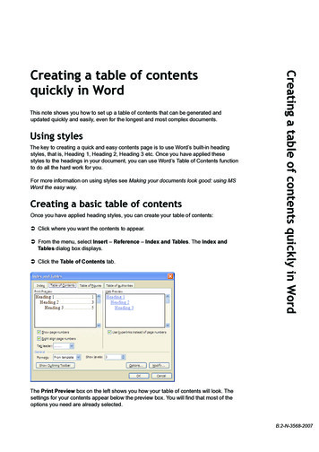
Table of ContentsParts Required . 6Introducing the Arduino . 8Traffic Lights .16LED Brightness on a 16x2 LCD .22Complete Guide for Ultrasonic Sensor HC-SR04 with Arduino .27Parking Sensor.34Gesture Slider Swiper .39Arduino with PIR Motion Sensor .46Control LEDs with IR Remote Control . 49Teensy/Arduino - Memory Game .58Guide for MQ-2 Gas/Smoke Sensor with Arduino .66Guide for 8 8 Dot Matrix MAX7219 Pong Game .72Security Access using MFRC522 RFID Reader with Arduino .86Arduino Time Attendance System with RFID .93Arduino Temperature Data Logger with SD Card Module . 111Android App – RGB LED with Arduino and Bluetooth . 118Control DC Motor via Bluetooth . 128Request Sensor Data via SMS . 133Night Security Light with Arduino . 149Ethernet Web Server with Relay . 154Resources . 163Wrapping Up . 165Arduino Step-by-step Projects Course . 166Download Other RNT Products . 1682Like Arduino? Get 25 Arduino Step-by-step Projects Course
DisclaimerThis eBook has been written for information purposes only. Every effort has beenmade to make this eBook as complete and accurate as possible.The purpose of this eBook is to educate. The author (Rui Santos) does not warrantthat the information contained in this eBook is fully complete and shall not beresponsible for any errors or omissions. The author (Rui Santos) shall have neitherliability nor responsibility to any person or entity with respect to any loss or damagecaused or alleged to be caused directly or indirectly by this eBook.This eBook contains code examples which you can use on your own projects,excepted where otherwise noted.You cannot redistribute this eBook.This eBook is only available for free download at: http://randomnerdtutorials.com/downloadPlease send an email to the author (Rui Santos - hello@ruisantos.me), if you find thiseBook anywhere else.3Like Arduino? Get 25 Arduino Step-by-step Projects Course
IntroductionThis eBook is a compilation of some of my most popular Arduino projects. For moreArduino projects, take a look at our Arduino project’s repository.I encourage you to watch some of the video demonstrations. Some of my projectsare easier to understand if you can see the circuit in action.This eBook has the purpose to inspire you create something amazing withelectronics and programing. After you create something cool, I hope you share itwith others. That’s the whole goal of this awesome community.To all my readers, thank you for your interest in my work. I really appreciate it!Have fun with your projects,Rui SantosP.S. Make sure you visit my website to see the latest projects!http://RandomNerdTutorials.com4Like Arduino? Get 25 Arduino Step-by-step Projects Course
Connect with RuiIf you have any questions, please don’t hesitate to contact me. Here are some waysto stay in touch.Visit my website(http://RandomNerdTutorials.com)Subscribe on orials)Like on als)Follow me on Twitter(https://twitter.com/RuiSantosdotme)Fork me on GitHub(https://github.com/RuiSantosdotme)Follow me on Like Arduino? Get 25 Arduino Step-by-step Projects Course
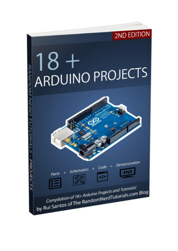
Parts RequiredTo build Arduino projects you need some electronics components beside the bareArduino board. In each project we provide a complete list of the needed parts andlinks to Maker Advisor, so that you can find the parts you're looking for on yourfavorite store at the best price.If you buy your parts through Maker Advisor links, we'll earn a small affiliatecommission (you won't pay more for it). By getting your parts through our affiliatelinks you are supporting our work. If there's a component or tool you're looking for,we advise you to take a look at our favorite tools and parts here.What do you need to get started?In our opinion, the best way to get started with the Arduino is by getting oneArduino starter kit that contains all the components you need to learn the basicsand start doing projects.Elegoo Arduino UNO R3 Complete Starter KitThere are a wide variety of Arduino Starter Kits. The best kit for you depends onwhat you want to do and how much you are willing to spend. We recommendreading the following article about the best Arduino Starter Kits for Beginners: Best Arduino Starter Kits - Buying Guide6Like Arduino? Get 25 Arduino Step-by-step Projects Course
There are also other tools we recommend you getting like a multimeter and asoldering iron.We have some articles to help you chose the best multimeter and soldering iron forbeginners: Best Soldering Irons for Beginners and Hobbyists Best Multimeters Under 50You may also find useful taking a look at the following article that gives you tips toset up your own electronics hobbyist lab: How To Set Up an Electronics Lab: Tools and Equipment7Like Arduino? Get 25 Arduino Step-by-step Projects Course
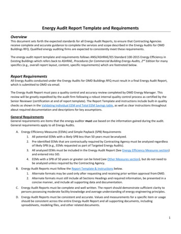
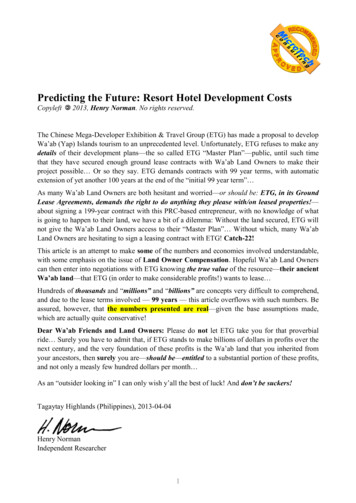
Introducing the ArduinoThe Arduino is a small computer that you can program to read information from theworld around you and send commands to the outside world. All of this is possiblebecause you can connect several devices and components to the Arduino to dowhat you want.You can do amazing projects with it, there is no limit for what you can do, and usingyour imagination everything is possible!What is an Arduino?The Arduino is the board shown in the figure below.Arduino UNO R3 board with ATmega328PBasically, it is a small development board with a brain (also known as amicrocontroller) that you can connect to electrical circuits. This makes it easy toread inputs – read data from the outside – and control outputs - send a commandto the outside. The brain of this board (Arduino Uno) is an ATmega328p chip whereyou can store your programs that will tell your Arduino what to do.Exploring the Arduino Uno BoardIn the figure below you can see an Arduino board labeled. Let’s see what each partdoes.8Like Arduino? Get 25 Arduino Step-by-step Projects Course
Microcontroller: the ATmega328p is the Arduino brain. Everything on theArduino board is meant to support this microcontroller. This is where youstore your programs to tell the Arduino what to do. Digital pins: Arduino has 14 digital pins, labeled from 0 to 13 that can act asinputs or outputs.o When set as inputs, these pins can read voltage. They can only readtwo states: HIGH or LOW.o When set as outputs, these pins can apply voltage. They can only apply5V (HIGH) or 0V (LOW). PWM pins: These are digital pins marked with a (pins 11, 10, 9, 6, 5 and 3).PWM stands for “pulse width modulation” and allows the digital pins output“fake” varying amounts of voltage. You’ll learn more about PWM later. TX and RX pins: digital pins 0 and 1. The T stands for “transmit” and the R for“receive”. The Arduino uses these pins to communicate with other electronicsvia Serial. Arduino also uses these pins to communicate with your computerwhen uploading new code. Avoid using these pins for other tasks other thanserial communication, unless you’re running out of pins. LED attached to digital pin 13: This is useful for an easy debugging of theArduino sketches. TX and RX LEDs: these leds blink when there are information being sentbetween the computer and the Arduino.9Like Arduino? Get 25 Arduino Step-by-step Projects Course
Analog pins: the analog pins are labeled from A0 to A5 and are often used toread analog sensors. They can read different amounts of voltage between 0and 5V. Additionally, they can also be used as digital output/input pins likethe digital pins. Power pins: the Arduino provides 3.3V or 5V through these pins. This is reallyuseful since most components require 3.3V or 5V to operate.The pinslabelled as “GND” are the ground pins. Reset button: when you press that button, the program that is currentlybeing run in your Arduino restarts. You also have a Reset pin next to thepower pins that acts as reset button. When you apply a small voltage to thatpin, it will reset the Arduino. Power ON LED: will be on since power is applied to the Arduino. USB jack: you need a male USB A to male USB B cable (shown in figurebelow) to upload programs from your computer to your Arduino board. Thiscable also powers your Arduino. Power jack: you can power the Arduino through the power jack. Therecommended input voltage is 7V to 12V. There are several ways to power upyour Arduino: rechargeable batteries, disposable batteries, wall-warts andsolar panel, for example. For more information about this subject you canread this blog post on Random Nerd Tutorials Arduino – 5 Ways to Power Upyour Arduino.Note: For more information about the Arduino hardware parts, visit theArduino official web page.10Like Arduino? Get 25 Arduino Step-by-step Projects Course
Downloading the Arduino IDEThe Arduino IDE (Integrated Development Environment) is where you develop yourprograms that will tell the Arduino what to do.You can load new programs onto the main chip, the ATmega328p, via USB using theArduino IDE. To download the Arduino IDE, please click on the following link:https://www.arduino.cc/en/Main/Software. Select which Operating System you’reusing and download it. Then, simply follow the installation wizard to install theArduino IDE.When you first open the Arduino IDE, you should see something similar to the figurebelow:11Like Arduino? Get 25 Arduino Step-by-step Projects Course
Connecting your ArduinoConnect your Arduino UNO to your computer via USB.After connecting your Arduino with a USB cable, you need to make sure that theArduino IDE has selected the right board.In our case, we’re using Arduino Uno, so we should go to Tools Board: Arduino/Genuino Uno.Then, you should select the serial port where your Arduino is connected to. Go toTools Port and select the right port.12Like Arduino? Get 25 Arduino Step-by-step Projects Course
Uploading an Arduino SketchTo show you how to upload code to your Arduino board, we’ll show you a simpleexample. This is one of the most basic examples – it consists in blinking theon-board LED or digital pin 13 every second.1. Open your Arduino IDE.2. Go to File Examples 01.Basics BlinkBy default, the Arduino IDE comes pre-configured for the Arduino UNO. Click theUpload button and wait a few seconds.13Like Arduino? Get 25 Arduino Step-by-step Projects Course
After a few seconds, you should see a Done uploading message.This code simply blinks the on-board LED on your Arduino UNO (highlighted withred color). You should see the little LED turn on for one second, and turn off foranother second repeatedly.Control an Output and Read an InputAn Arduino board contains digital pins, analog pins and PWM pins.Difference between digital, analog and PWMIn digital pins, you have just two possible states, which are on or off. These can alsobe referred as High or Low, 1 or 0 and 5V or 0V.For example, if an LED is on, then, its state is High or 1 or 5V. If it is off, you’ll haveLow, or 0 or 0V.In analog pins, you have unlimited possible states between 0 and 1023. This allowsyou to read sensor values. For example, with a light sensor, if it is very dark, you’llread 1023, if it is very bright you’ll read 0 If there is a brightness between dark andvery bright you’ll read a value between 0 and 1023.14Like Arduino? Get 25 Arduino Step-by-step Projects Course
PWM pins are digital pins, so they output either 0 or 5V. However these pins canoutput “fake” intermediate voltage values between 0 and 5V, because they canperform “Pulse Width Modulation” (PWM). PWM allows to “simulate” varying levelsof power by oscillating the output voltage of the Arduino.Controlling an outputTo control a digital output you use the digitalWrite() function and betweenbrackets you write, the pin you want to control, and then HIGH or LOW.To control a PWM pin you use the analogWrite() function and between bracketsyou write the pin you want to control and a number between 0 and 255.Reading an inputTo read an analog input you use the function analogRead() and for a digital inputyou use digitalRead().The best way for you to learn Arduino is practising. So, choose a project and startbuilding something.15Like Arduino? Get 25 Arduino Step-by-step Projects Course
Traffic LightsView code on GitHubClick hereIntroductionIn this project you’re going to build a traffic lights system: There are 3 LEDs with different colors (green, yellow and red) to mimic thetraffic lights for the cars There are 2 LEDs with different colors (green and red) to mimic the trafficlights for the pedestrians There is a pushbutton to mimic the ones in the pedestrians traffic lights16Like Arduino? Get 25 Arduino Step-by-step Projects Course
Parts RequiredGrab all the needed components for this project. 1x Breadboard Arduino UNO – read Best Arduino Starter Kits 3x 5mm LED (1x red, 1x yellow, 1x green) 2x 3mm LED (1x red, 1x green) 5x 220Ohm Resistor 1x 10kOhm Resistor 1x pushbutton Jumper WiresI’m using LEDs of different sizes but if you don’t have LEDs of different sizes, it is ok.The project still works.17Like Arduino? Get 25 Arduino Step-by-step Projects Course
SchematicsAssemble all the parts by following the schematics below.CodeYou don’t need any library for this code. The code is very simple. Here’s some tipsto better understand what’s going on. The car light is always green, and so the pedestrian light is always red unlesssomeone presses the button. When someone presses the button here’s what happens: The car light changes to yellow and then to red The pedestrian light changes to green18Like Arduino? Get 25 Arduino Step-by-step Projects Course
The lights are in this state for a while (in the code this time is thevariable crossTime) The pedestrian green light flashes and goes to red The car light changes from red to greenAll these actions will be inside the function changeLights(). Everytime you want tochange the lights, you just need to call the changeLights() function.Copy the following code to your Arduino IDE, and upload it to your Arduino board.Make sure you have the right board and COM port selected.View code on GitHub/** Rui Santos* Complete Project Details http://randomnerdtutorials.com*/int redCar 13;int yellowCar 12;int greenCar 11;int greenPed 2;int redPed 3;int button 7;int crossTime 2000;unsigned long changeTime;void setup() {// initialize timerchangeTime millis();// here we are initializing our pins as outputspinMode(redCar, OUTPUT);pinMode(yellowCar, OUTPUT);pinMode(greenCar, OUTPUT);pinMode(redPed, OUTPUT);pinMode(greenPed, OUTPUT);pinMode(button, INPUT);//turn on the green lightdigitalWrite(greenCar, HIGH);digitalWrite(redPed, HIGH);digitalWrite(redCar, LOW);digitalWrite(yellowCar, LOW);digitalWrite(greenPed, LOW);19Like Arduino? Get 25 Arduino Step-by-step Projects Course
Serial.begin(9600);}void loop() {// this variable will tell us if the button is pressedint state digitalRead(button);Serial.println(state);// if the button is pressed and if it has passed 5 seconds since last buttonpressif (state HIGH && (millis() - changeTime) 5000) {//call the function to change the lightschangeLights();}}void changeLights() {digitalWrite(greenCar, LOW);// the green LED will turn offdigitalWrite(yellowCar, HIGH); // the yellow LED will turn on for 2 seconddelay(2000);digitalWrite(yellowCar, LOW); // the yellow LED will turn offdigitalWrite(redCar, HIGH); // the red LED will turn on for 5 secondsdigitalWrite(redPed, LOW);digitalWrite(greenPed, HIGH);delay(crossTime);// flash the ped greenfor (int x 0; x 10; x ) {digitalWrite(greenPed, LOW);delay(100);digitalWrite(greenPed, HIGH);delay(100);}digitalWrite(greenPed, LOW);digitalWrite(redCar, LOW);digitalWrite(redPed, HIGH);digitalWrite(greenCar, HIGH);changeTime millis();}20Like Arduino? Get 25 Arduino Step-by-step Projects Course
DemonstrationWhen you press the button, the light for the cars changes from green to red, andthe pedestrian light changes from red to green.After the crosstime, the pedestrian green led flashes and changes to red. The lightfor the cars changes from red to green.Wrapping UpIf you’re starting with the Arduino, a good exercise is to change the value of somevariables like crossTime and changeTime and see what happens.If you want something a little bit more challenging, try to mimic what happens in ajunction, with several lights for several cars and pedestrians.21Like Arduino? Get 25 Arduino Step-by-step Projects Course
LED Brightness on a 16x2 LCDView Project on Random Nerd TutorialsClick hereWatch on YouTubeClick hereView code on GitHubClick hereIntroductionThis is a beginner project where you’ll use a 16 2 LCD to display the LED brightness.Shortly, in this project we’ll control an LED brightness using a potentiometer. TheLED brightness will be displayed on the LCD screen using a progress bar22Like Arduino? Get 25 Arduino Step-by-step Projects Course
Watch the video belowWatch on YouTube: http://youtu.be/sAklcqiywPwIntroducing the LCDThe simplest and inexpensive way to display information is with an LCD (liquidcrystal display). These are found in everyday electronics devices such as vendingmachines, calculators, parking meters, printers, and so on. These are ideal fordisplaying text or small icons. The figure below shows a 16 2 LCD front and backview.This LCD has 2 rows, and each row can display 16 characters. It also has LEDbacklight to adjust the contrast between the characters and the background.23Like Arduino? Get 25 Arduino Step-by-step Projects Course
Parts RequiredFor this project you need the following parts: Arduino UNO – read Best Arduino Starter Kits 1x Breadboard 1x LCD 16 2 2x 10k Ohm Potentiometers 1x 5mm LED 1x 220Ohm Resistor Jumper wiresSchematicsWire all the parts by following the next schematic diagram.24Like Arduino? Get 25 Arduino Step-by-step Projects Course
The next table shows a brief description of each pin of the LCD display. Make sureyour LCD uses the same pinout.CodeCopy the following code and upload it to your Arduino board. The code is wellcommented so that you can easily understand how it works, and modify it toinclude in your own projects.View code on GitHub/*Created by Rui SantosAll the resources for this project:http://randomnerdtutorials.com/Based on some Arduino code examples*/// include the library code#include LiquidCrystal.h // initialize the libraryLiquidCrystal lcd(12, 11,int potPin A0;//int ledPin 6;//int potValue 0;potentiometerint brightness 0;//int pBari 0;//int i 0;//with the numbers of the interface pins5, 4, 3, 2);Analog pin 0 for the LED brightness potentiometerLED Digital Pin with PWM// variable to store the value coming from theconverts the potValue into a brightnessprogress barfoor loop//progress bar character for brightnessbyte pBar[8] {B11111,B11111,B11111,B11111,B11111,B11111,25Like Arduino? Get 25 Arduino Step-by-step Projects Course
B11111,};void setup() {// setup our led as an OUTPUTpinMode(ledPin, OUTPUT);// set up the LCD's number of columns and rows:lcd.begin(16, 2);// Print a message to the LCDlcd.print(" LED Brightness");//Create the progress bar characterlcd.createChar(0, pBar);}void loop() {// clears the LCD screenlcd.clear();// Print a message to the LCDlcd.print(" LED Brightness");//set the cursor to line number 2lcd.setCursor(0,1);// read the value from the potentiometerpotValue analogRead(potPin);// turns the potValue into a brightness for the LEDbrightness map(potValue, 0, 1024, 0, 255);//lights up the LED according to the bightnessanalogWrite(ledPin, brightness);// turns the brighness into a percentage for the barpBari map(brightness, 0, 255, 0, 17);//prints the progress barfor (i 0; i pBari; i ){lcd.setCursor(i, 1);lcd.write(byte(0));}// delays 750 msdelay(750);}26Like Arduino? Get 25 Arduino Step-by-step Projects Course
Complete Guide for UltrasonicSensor HC-SR04 with ArduinoView Project on Random Nerd TutorialsView code on GitHubClick hereClick hereClick hereThis project is about the Ultrasonic Sensor HC – SR04. We’ll explain how it works,show some features and share an Arduino Project example. We provide a schematicdiagram on how to wire the ultrasonic sensor, and an example sketch to use withyour Arduino.DescriptionThe HC-SR04 ultrasonic sensor uses sonar to determine distance to an object likebats do. It offers excellent non-contact range detection with high accuracy andstable readings in an easy-to-use package. From 2cm to 400 cm or 1” to 13 feet. Itsoperation is not affected by sunlight or black material like sharp rangefinders are(although acoustically soft materials like cloth can be difficult to detect). It comescomplete with ultrasonic transmitter and receiver module.27Like Arduino? Get 25 Arduino Step-by-step Projects Course
Features Power Supply : 5V DC Quiescent Current : 2mA Working Current: 15mA Effectual Angle: 15 Ranging Distance : 2cm – 400 cm/1″ – 13ft Resolution : 0.3 cm Measuring Angle: 30 degree Trigger Input Pulse width: 10uSHow Does it Work?The ultrasonic sensor uses sonar to determine the distance to an object. Here’swhat happens:1. The transmitter (trig pin) sends a signal: a high-frequency sound;2. When the signal finds an object, it is reflected and 3. The transmitter (echo pin) receives it.The time between the transmission and reception of the signal allows us tocalculate the distance to an object. This is possible because we know the sound’svelocity in the air.28Like Arduino? Get 25 Arduino Step-by-step Projects Course
Sensor Pins VCC: 5VDC Trig : Trigger (INPUT) Echo: Echo (OUTPUT) GND: GNDWhere to buy?You can check the Ultrasonic Sensor HC-SR04 sensor on Maker Advisor and find thebest price.Arduino with HC – SR04 SensorIn this project the ultrasonic sensor reads and writes the distance to an object in theSerial Monitor.The goal of this project is to help you understand how this sensor works. Then, youcan use this example in your own projects.Note: There’s an Arduino library called NewPing that can make your life easier whenusing this sensor.29Like Arduino? Get 25 Arduino Step-by-step Projects Course
Parts Required Arduino UNO – read Best Arduino Starter Kits Ultrasonic Sensor (HC-SR04) Breadboard Jumper wiresSchematicsFollow the next schematic diagram to wire the HC-SR04 ultrasonic sensor to theArduino.The following table shows the connections you need to make:Ultrasonic Sensor HC-SR04ArduinoVCC5VTrigPin 11EchoPin 12GNDGND30Like Arduino? Get 25 Arduino Step-by-step Projects Course
CodeUpload the following code to your Arduino IDE.View code on GitHub/** created by Rui Santos, http://randomnerdtutorials.com** Complete Guide for Ultrasonic Sensor HC-SR04*Ultrasonic sensor Pins:VCC: 5VDCTrig : Trigger (INPUT) - Pin11Echo: Echo (OUTPUT) - Pin 12GND: GND*/int trigPin 11;//Trig - green Jumperint echoPin 12;//Echo - yellow Jumperlong duration, cm, inches;void setup() {//Serial Port beginSerial.begin (9600);//Define inputs and outputspinMode(trigPin, OUTPUT);pinMode(echoPin, INPUT);}void loop(){// The sensor is triggered by a HIGH pulse of 10 or more microseconds.// Give a short LOW pulse beforehand to ensure a clean HIGH pulse:digitalWrite(trigPin, LOW);delayMicroseconds(5);digitalWrite(trigPin, HIGH);delayMicroseconds(10);digitalWrite(trigPin, LOW);// Read the signal from the sensor: a HIGH pulse whose31Like Arduino? Get 25 Arduino Step-by-step Projects Course
// duration is the time (in microseconds) from the sending// of the ping to the reception of its echo off of an object.pinMode(echoPin, INPUT);duration pulseIn(echoPin, HIGH);// convert the time into a distancecm (duration/2) / 29.1;inches (duration/2) / 74;Serial.print(inches);Serial.print("in, tln();delay(250);}Code with NewPingYou can also use the the NewPing library. Download the library here. After installingthe NewPin library, you can upload the code provided below.View code on GitHub/** Posted on http://randomnerdtutorials.com* created by e NewPing.h #define TRIGGER PIN 11#define ECHO PIN 12#define MAX DISTANCE 200NewPing sonar(TRIGGER PIN, ECHO PIN, MAX DISTANCE); // NewPing setup of pinsand maximum distance.void setup() {Serial.begin(9600);}void loop() {delay(50);unsigned int uS sonar.ping Like Arduino? Get 25 Arduino Step-by-step Projects Course
TroubleshootingNOTE: “If the HC-SR04 does not receive an echo then the output never goeslow. Devantec and Parallax sensors time out after 36ms and I think 28msrespectively. If you use Pulsin as above then with no return echo the program willhang for 1 second which is the default timeout for Pulsin. You need to use thetimeout e HC-SR04 barely works to 10 feet giving a total path length of 20 feet and a pathtime of about 20ms so set the timeout to something above that, say 25 or 30ms.If you put a resistor, say 2k2 between E and T then only connect to T you can use theHC-SR04 from just one Arduino pin. Look up single pin operation of ultrasonicsensors.Also if you are using a HC-SR04 with a PicAxe you need to up the clockspeed to atleast 8MHz otherwise they don’t see the start of the echo pulse so pulsin neverstarts. The HC-SR04 works fine with a BS2.” by David BuckleyWrapping UpIn this post we’ve shown you how the HC-SR04 ultrasonic sensor works, and howyou can use it with Arduino. If you are a beginner to the Arduino, we recommendfollowing our Arduino Mini Course that will help you quickly getting started with thisamazing board.33Like Arduino? Get 25 Arduino Step-by-step Projects Course
Parking SensorView Project on Random Nerd TutorialsClick hereWatch on YouTubeClick hereView code on GitHubClick hereIntroductionIn this project we have an ultrasonic sensor that measures the distance and an LEDbar graph that lights up accordingly to our distance from the sensor. As we getcloser to the sensor the buzzer beeps in a different way. This circuit can work as aparking sensor.34Like Arduino? Get 25 Arduino Step-by-step Projects Course
Parts Required Arduino UNO – read Best Arduino Starter Kits 1x 74HC595 8 Bit Shift Register 1x Breadboard 8x LEDs (for example: 3x red, 3x yellow, 2x green) 9x 220 Ohm Resistors 1x Buzzer 1x Ultrasonic Sensor (for exemple: HC-SR04) Jumper WiresSchematicsAssemble the circuit by following the next schematic diagram:35Like Arduino? Get 25 Arduino Step-by-step Projects Course
CodeUpload the following code to your Arduino board:View code on GitHub/** created by Rui Santos, http://randomnerdtutorials.com* Ultrasonic Sensor with LED's bar graph and buzzer*/int tonePin 4;//Tone - Red Jumperint trigPin 9;//Trig - violet Jumperint echoPin 10;//Echo - yellow Jumperint clockPin 11;//IC Pin 11 - white Jumperint latchPin 12;//IC Pin 12 - Blue Jumperint dataPin 13;//IC Pin 14 - Green Jumperbyte possible patterns[9] ,B00011111,B00111111,B01111111,B11111111,};int proximity 0;int duration;int distance;void setup() {//Serial PortSerial.begin (9600);pinMode(trigPin, OUTPUT);pinMode(echoPin, INPUT);pinMode(clockPin, OUTPUT);pinMode(latchPin, OUTPUT);pinMode(dataPin, OUTPUT);pinMode(tonePin, OUTPUT);}36Like Arduino? Get 25 Arduino Step-by-step Projects Course
void loop() {digitalWrite(latchPin, LOW);digitalWrite(trigPin, , LOW);duration pulseIn(echoPin, HIGH);distance (duration/2) / 29.1;/*if (distance 45 distance 0){Serial.println("Out of range");}else {Serial.print(distance);Serial.println(" cm");}*/proximity map(distance, 0, 45, 8, 0);//Serial.println(proximity);if (proximity 0){proximity 0;}else if (proximity 3 && proximity 4){tone(tonePin, 200000, 200);}else if (proximity 5 && proximity 6){tone(tonePin,5000, 200);}else if (proximity 7 && proximity 8){tone(tonePin, 1000, 200);}shiftOut(dataPin, clockPin, MSBFIRST, possible patterns[proximity]);digi
Arduino starter kit that contains all the components you need to learn the basics and start doing projects. Elegoo Arduino UNO R3 Complete Starter Kit There are a wide variety of Arduino Starter Kits. The best kit for you depends on what you want