Transcription
Technical DataE1 Plus Overload Relay SpecificationsBulletin Numbers 193, 592TopicSummary of ChangesProduct OverviewFeaturesCatalog Number ExplanationSpecificationsApproximate DimensionsPage1236713Summary of ChangesThis publication has been reformatted from its original layout.Additional ResourcesThese documents contain additional information concerning related products from Rockwell Automation.ResourceDescriptionIndustrial Automation Wiring and Grounding Guidelines, publication 1770-4.1Provides general guidelines for installing a Rockwell Automation industrial system.Product Certifications website, tion/overview.pageProvides declarations of conformity, certificates, and other certification details.You can view or download publications at e-library/overview.page. To order paper copies oftechnical documentation, contact your local Allen-Bradley distributor or Rockwell Automation sales representative.
E1 Plus Overload Relay SpecificationsProduct OverviewBulletin193-ED193-EETypeRated Current (Range)NEMA Operating Voltage, NominalIEC Operating Voltage, NominalOverload TypeTrip Class (Fixed)Trip Class (Adjustable)Ambient Temperature CompensatedReset TypeAdjustment RangePhase LossGround (Earth) FaultOvercurrent (Jam) DetectionStall DetectionUnderload DetectionCurrent ImbalancePTC Thermistor MonitoringWarning SettingsN.C. Trip ContactN.O. Alarm ContactNo. of OutputsNo. of InputsODVA (DeviceNet) ConformanceVariable Frequency Drive (VFD)CompatibleE1 Plus Electronic Overload RelayE1 Plus Electronic Overload Relay0.1 45 A0.1 800 A—600V690V690/1000VElectronic OverloadElectronic Overload10——10, 15, 20, 30Manual OnlyAutomatic and ��Standards Compliance IEC/EN 60947-4-1 IEC/EN 60947-5-1 CSA 22.2 No. 14 UL 508Certifications CE cULus Listed C-Tick CCC2Rockwell Automation Publication 193-TD011B-EN-P - January 2017
E1 Plus Overload Relay SpecificationsFeaturesAccurate, Reliable PerformanceCurrent measurement-based protectionWhile electromechanical overload relays pass motor current through heating elements to provide an indirect simulation of motor heating, theE1 Plus Overload Relay directly measures motor current. Current measurement-based overload protection more accurately models a motor’sthermal condition. Furthermore, ambient temperature does not impact the performance of current measurement-based designs over the specifiedtemperature operating range.Electronic designThermal modeling is performed electronically with precision solid- state components, where at the heart of the E1 Plus Overload Relay is anapplication-specific integrated circuit (ASIC). The ASIC continually processes motor current data to accurately maintain the time-current status ofthe motor thermal capacity utilization value.Thermal memoryA thermal memory circuit allows the E1 Plus Overload Relay to model the heating and cooling effects of motor on and off periods. This ensuresaccurate protection for both hot and cold motors.Enhanced phase loss protectionA separate phase loss detection circuit incorporated into the E1 Plus Overload Relay allows it to respond quickly to phase loss conditions; typicalreaction time is 3 seconds.Easy to Select and ApplyStraightforward installationThe self-powered design means that the E1 Plus Overload Relay installs in the same manner as traditional overload relays. Device setup isaccomplished by simply dialing the setting potentiometer to the motor FLA rating. The low energy consumption of the electronic design minimizestemperature rise issues inside control cabinets.Wide adjustment rangeA wide 5:1 adjustment range results in the need for half as many catalog numbers as the bimetallic alternative in order to cover the same currentrange. This helps to reduce inventory carrying costs and affords greater installation flexibility for dual voltage machines. Evenly spaced setting tickmarks enhance the ease of installation setup.Rugged ConstructionOver-molded power connectionsThe unique line-side over-molded power connections make for a sturdy two-component starter assembly that is unmatched in the industry. Thepre-formed power connections allow easy starter assembly—every time.Current transformersThe current transformers are secured separately in the overload housing to ensure the greatest degree of resistance to shock and vibration conditions.Varnished laminations ensure consistent performance and provide additional protection against corrosion.Rockwell Automation Publication 193-TD011B-EN-P - January 20173
E1 Plus Overload Relay SpecificationsLatching relayThe robust design of the bi-polar latching relay provides reliable trip and reset performance for the most demanding of applications. The selfenclosed relay offers additional environmental protection for use in industrial applications.Application FlexibilityIsolated ContactsThe isolated contact configuration allows the N.C. and N.O. contacts to be applied in circuits operating at different voltage levels and withoutpolarity restrictions. The B600 contact rating affords application in circuits rated to 600V.DIP switch settings193-EE devices offer DIP switch settings to select the trip class (10, 15, 20 or 30) and the reset mode (manual or automatic), making these devicesextremely versatile.Pass-thru OptionThe E1 Plus Pass-thru consumes 48% less panel space compared to a standard E1 Plus mounted in a panel mount adapter. The design provides anintegrated DIN Rail mount and panel mounting holes and is intended for the following applications: DIN Rail and Panel Mount Applications,Bulletin 100-K mini contactor, external current transformers, and for use with non Allen-Bradley contactors. The E1 Plus Pass-thru ElectronicOverload Relay provides all of the same expandable protection & communication capabilities as a standard E1 Plus, and eliminates the need for aseparate panel mount adapter, which saves money and valuable panel space.Side-Mount Expansion ModulesThrough the use of optional side-mount expansion modules, functionality of the E1 Plus overload relays can be cost effectively expanded andmachine operation and protection enhanced. Direct mounting to the left side of the 193-EE and 592-EE E1 Plus overload relays means that only18 mm is added to the overall product width. The side-mounted accessory modules electronically interface with the E1 Plus overload relay so thatall control circuit connections are made at the E1 Plus overload relay terminals.E1 Plus DeviceNet Communication ModuleThe 193-EDN DeviceNet Communication Side-Mount Module provides a cost-effective, seamless deployment of motor starters onto theIntegrated Architecture as an accessory for the E1 Plus electronic overload relay. The DeviceNet module provides Integrated I/O (2 inputs and 1output) providing local connection of motor starter-related I/O. The DeviceNet module offers expanded protective functions including overloadwarning, jam protection, and underload warning. The DeviceNet module also allows access to average motor current (percentage of FLA setting),percentage of thermal capacity usage, device status, trip & warning identification, and trip history which allows continual monitoring of motorperformance.E1 Plus remote reset moduleThe 193-ERR Remote Reset Module is available for applications that require remote reset of the E1 Plus overload relays after a trip occurs.E1 Plus jam protection module with remote resetThe 193-EJM Jam Protection Module provides front-accessible DIP switches which offers flexibility to provide jam protection to matchapplication requirements. Selections are available for enabling or disabling the jam protection function and remote reset operation. Jam trip levelsettings are available at 150%, 200%, 300%, and 400% of full load current setting. Trip delay settings of 1/2, 1, 2, and 4 seconds are available tominimize nuisance tripping in applications where intermittent short-duration overloading is permissible.4Rockwell Automation Publication 193-TD011B-EN-P - January 2017
E1 Plus Overload Relay SpecificationsE1 Plus ground fault module with remote resetThe 193-EGF Ground Fault Protection Module offers front- accessible DIP switches providing flexibility to configure ground fault protection tomatch application requirements. Selections are available for enabling or disabling the ground fault protection function and remote reset operation.Ground fault trip level settings are available in four ranges: 20 100 mA (resistive loads only; for motor loads, consult your local RockwellAutomation sales office or Allen-Bradley distributor), 100 500 mA, 0.2 1 A, and 1 5 A. Within each range, the specific ground fault trip levelcan be set (20%, 35%, 50%, 65%, 80%, 90%, or 100% of the maximum ground fault setting). Trip delay is fixed at 50 ms 20 ms.E1 Plus ground fault/jam module with remote resetThe 193-EGJ Ground Fault/Jam Protection Module offers front- accessible DIP switches to provide flexibility to configure ground fault and jamprotection to match application requirements. The ground fault selections are the same as the 193-EGF Ground Fault Protection Module. Inaddition to ground fault, this module offers selectable fixed jam protection. The user can enable or disable jam protection from the DIP switches.The jam protection is fixed at 400% of the full load current setting with a 0.5 second trip delay.E1 Plus PTC module with remote resetThe 193-EPT PTC Side-mount Module provides two terminals for the connection of positive temperature coefficient (PTC) thermistor sensors.PTC sensors are commonly embedded in the motor stator windings to monitor winding temperature. PTC sensors react to actual temperature, soenhanced motor protection can be provided to address conditions like obstructed cooling and high ambient temperature.E1 Plus EtherNet/IP moduleThe 193-ETN EtherNet/IP network communication module delivers seamless control and direct access to motor performance and diagnostic dataon an Ethernet-based network. It supports I/O and explicit messaging for data access by a programmable automation controller, and containspredefined ControlLogix style tags for direct software access. The integrated web and e-mail server contains a web server to allow users to readinformation and configure parameters via a web browser. The device also uses a simple mail transfer protocol (SMTP) server to send e-mail or textmessages in the event of a warning or trip condition.E1 Plus PROFIBUS moduleThe 193-EPRB PROFIBUS network communication module delivers direct access to motor performance and diagnostic data on a field bus basednetwork in addition to seamless control. The PROFIBUS communication module supports both PROFIBUS DP- V0 and DP-V1. Protectivefunctions include overload warning, jam protection, and underload warning. The PROFIBUS network communication module monitors themotor current by electronically interfacing to the E1 Plus overload relay’s current-sensing circuit. As a result, the side-mount module is able toidentify the cause of the trip and provides warnings for overload, underload, phase loss, and jam. The module continuously monitors the motor’sperformance for average motor current, thermal capacity usage, and device status, and also provides a trip history for the five previous trips.Integrated I/O provides convenient local termination of motor-related inputs and outputs, simplifying the control architecture.Rockwell Automation Publication 193-TD011B-EN-P - January 20175
E1 Plus Overload Relay SpecificationsCatalog Number Explanation193–EEaCodeabBulletin NumberTypebCcBdcAdjustment criptiondBulletin 100 IEC Contactor EC Three-PhaseED1(1)Fixed Trip Class 10A0.1 0.5P1.0 5.0BC09 C23193SIEC Single-PhaseEESelectable Trip ClassB0.2 1.0R3.2 16DC30 C43592NEMA Three-PhaseC1.0 5.0S5.4 27EC60 C97592SNEMA Single-PhaseD3.2 16T9 45FD115 D180E5.4 27U18 90GD210 D420F9 45V60 120HG18 90——H30 150——CodeJ40 200——TSize 00K60 300——CSize 0 2DL100 500——M120 600——N160 800——(1) Bulletin 193 overload relays only6Rockwell Automation Publication 193-TD011B-EN-P - January 2017D630 D860Bulletin 500 NEMA Contactor SizeDescriptionSize 3Panel/DIN rail mountCodeDescriptionPIntegrated panel mount and passthrough wiringZPanel mount with external currenttransformers
E1 Plus Overload Relay SpecificationsSpecificationsFeaturesFunctionE1 Plus(1)(Cat. No. 193/592- EE )E1 Plus w/ JamModule(Cat. No. 193EJM)E1 Plus w/Ground FaultModule(2)(Cat. No.193-EGF)Manual/Automatic ResetGroundFaultProtectionPTCProtectionE1 Plus w/DeviceNetModule(Cat. No.193-EDN)E1 Plus w/EtherNet/IPModule(Cat. No.193-ETN)E1 Plus w/ProfibusModule(Cat. No. XXXXXXXOn or Off—X—X——XXXTrip Level—Adjustable 150/200/300/400%—Fixed @ 400%——Trip Delay—Adjustable 0.5/1.0/2.0/4.0 s—Fixed @ 0.5 s——Adjustable0.5 25 sAdjustable0.5 25 sAdjustable0.5 25 sInhibit—DynamicInhibit(1)—Dynamic DynamicInhibit(1)Type——Core- BalancedGround FaultProtection(2)Core- BalancedGround FaultProtection(2)—————On or Off——XX—————Adjustable20 mA 5 A(3)——————————Selectable Trip ClassJamProtectionE1 Plus w/E1 Plus w/E1 Plus w/ PTCGround Fault/Remote ResetModuleJam Module(2)Module (Cat.(Cat. No.(Cat. No. 193No. 150 600% FLA 150 600% FLA 150 600% FLATrip Level——Adjustable20 mA 5 A(3)Trip Delay——Fixed @ 50 ms Fixed @ 50 ms 20 ms20 msInhibit——DynamicInhibit(1)Dynamic ————————PTC Open Circuit————X————PTC Short Circuit————X————Remote Reset Capability—XXXXXXXXFault Indication——XXX—XXX(1) Dynamic Inhibit: Protective function is enabled after the motor current goes above 150% and then falls to below 125%.(2) Requires use of an external ground fault sensor, Cat. No. 193-CBCT .(3) From 20 100 mA for resistive loads only.DIN Rail / Panel Adapter - Terminal Cross SectionsCat. No. 193-EPB(1)Cat. No. 193-EPD(1)Cat. No. 193-EPE22.5 16 mm24.0 35 mm2Torque1.8 N m2.3 N m4.0 N mTwo Conductor1.0 4.0 mm22.5 10 mm24.0 25 mm2DescriptionSingle ConductorFlexible-Stranded with FerruleCoarse-Stranded/SolidStranded/Solid1.0 4.0 mmDeTorque1.8 N m2.3 N m4.0 N mSingle Conductor1.5 6.0 mm22.5 25 mm24.0 50 mm2Torque1.8 N m2.3 N m4.0 N mTwo Conductor1.5 6.0 mm22.5 16 mm24.0 35 mm2Torque1.8 N m2.3 N m4.0 N mSingle Conductor14 8 AWG16 6 AWG12 1 AWGTorque16 lb in20 lb in35 lb inTwo Conductor14 10 AWG16 6 AWG12 2 AWGTorque16 lb in20 lb in35 lb in(1) For multiple-conductor applications, the same size and style wire must be used.Rockwell Automation Publication 193-TD011B-EN-P - January 20177
E1 Plus Overload Relay SpecificationsGeneral SpecificationsCat. No. 193- ED1 B, Cat. No. 193- EE D, and193-EE B, 592-EE T592- EE CCat. No. 193- EE E,and 592- EE DCat. No. 193-EE F(1)Cat. No. 193EE GCat. No. 193- EE HMain CircuitsRated Insulation Voltage (Ui)690V ACRated Impulse Strength (Uimp)6 kV AC6 kV AC690V AC/600V AC1000V AC/600V AC50/60 Hz (sinusoidal)50/60 Hz (sinusoidal)Rated Operating Voltage (Ue) IEC/ULRated Operating FrequencyTerminal CrossSections1000V ACTerminal TypeTerminal ScrewsM5M822Flexible-Stranded with Single-Conductor Torque 2.5 16 mm , 2.5 N m 2.5 16 mm , 2.5 N m22(2)FerruleTwo-Conductor Torque 2.5 10 mm ‡, 3.4 N m 2.5 10 mm , 3.4 N mLug4 35 mm2, 24 N m———4 25 mm2, 4 N m———2.5 25 mm2, 2.5 N m4 50 mm2, 4 N m16 150 mm2, 28 N m——3.4 N m6 16 mm2(2), 3.4 N m4 35 mm2, 4 N m—25 185mm2,28 N m70 240 mm2, 45 N mFour-Conductor Torque6 16 mm2(2), 3.4 N m6 16 mm2(2), 3.4 N m4 35 mm2, 4 N m——70 240 mm2, 45 N mSingle-Conductor Torque14 6 AWG, 22 lb in14 6 AWG, 22 lb in12 1 AWG, 35 lb in6 300 MCM, 250 lb in——Single-Conductor Torque 2.5 25 mm2, 2.5 N mCoarse- Stranded/Solid Two-Conductor Torque6 16mm2(2),(2)(2)4 350 MCM,2/0 500 MCM, 400 lb in250 lb inTwo-Conductor Torque14 6 AWG , 30 lb in14 6 AWG , 30 lb in6 2 AWG, 35 lb in—Four-Conductor Torque14 6 AWG(2), 30 lb in14 6 AWG(2), 30 lb in6 2 AWG, 35 lb in——Pozidriv Screwdriver Size22————Slotted Screwdriver (mm)1x61x6————Hexagon Socket Size (mm)——4888Stranded/Solid2/0 500 MCM, 400 lb inControl CircuitsRated Insulation Voltage (Ui)690V ACRated Impulse Strength (Uimp)6 kV ACRated Operating Voltage (Ue) IEC/UL690V AC / 600V ACB600N.O./N.C.Rating DesignationRated Operating Current IeAC-1512 120V3/2220 240V1.5/1.5380 480V0.75/0.75500 600V0.6/0.6Thermal Current Ithe5AContact Reliability17V, 5 mAScrew TerminalCross SectionsFlexible-Strandedwith FerruleCoarse- Stranded/SolidStranded/SolidTerminal ScrewM30.5 2.5 mm2, 0.55 N mSingle-Conductor TorqueTwo-Conductor Torque20.2 0.75 mm2, 0.55 N m0.25 1.5 mm , 0.55 N m0.5 4 mm0.55 N mSingle-Conductor Torque20.2 2.5 mm2, 0.55 N mTwo-Conductor TorqueSingle-Conductor Torque0.2 1.5mm2, 0.55 N m24 10 AWG, 5 lb inTwo-Conductor Torque24 12 AWG, 5 lb inScrewdriver Size (mm)22 16 AWG, 5 lb in#1 Pozidriv/0.6 x 3.5 slottedCage Clamp Cross SectionsFlexible-Stranded with Ferrule0.25 1 mm2Coarse-Stranded/Solid0.2 1.5 mm2Stranded/Solid24 14 AWG(1) Cat. Nos. 193-EEGF and 193-EEVF follow Cat. No. 193-EE E specifications.(2) For multiple conductor applications, the same style and size of wire must be used.8Rockwell Automation Publication 193-TD011B-EN-P - January 2017
E1 Plus Overload Relay Specifications3-Pole Terminal BlocksCat. No. 100-DTB180Cat. No. 100-DTB420(A) 6 1/0 AWG, 16 50 mm2(B) 6 AWG 250 MCM, 16 120 mm290 110 lb in, 10 12 N m(2) 4 AWG 600 MCM, 25 240 mm2180 220 lb in, 20 25 N mTerminal Lug KitsLugCat. No. 100-DLE110Cat. No. 100-DL180Cat. No. 100-DL420Cat. No. 100-DL630Cat. No. 100-DL8606 2/0 AWG, 16 70 mm290 110 lb in, 10 12 N m6 AWG 250 MCM, 16 120 mm290 110 lb in, 10 12 N m2 AWG 350MCM,375 lb in, 42 N m2/0 AWG 500 MCM,70 240 mm2 400 lb in, 45 N m2/0 AWG 500 MCM,70 240 mm2 400 lb in, 45N m13/32 in., 10 mm150 lb in, 17 N m1/2 in., 13 mm275 lb in, 16 N m11/16 in., 17 mm140 lb in, 16 N m3/4 in., 19 mm600 lb in, 68 N m3/4 in., 19 mm600 lb in, 68 N mTerminalEnvironmental RatingsAttributeAmbient TemperatureHumidityDescriptionStorage-40 85 C (-40 185 F)Operating-20 60 C (-4 140 F)Operating5 95% Non-condensingDamp Heatper IEC 68-2-3 and IEC68-2-30Vibration (per IEC 68-2-6)3GShock (per IEC 68-2-27)30 GMax. Altitude2000 mPollution EnvironmentPollution Degree 3Degree of ProtectionIP20ProtectionType of RelayAmbient Compensated, Time Delay, Phase Loss SensitiveNature of RelaySolid-StateTrip RatingTrip ClassReset Mode120% FLAType ED10Type EE10, 15, 20, 30Type EDManualType EEAutomatic or ManualElectromagnetic CompatibilityElectrostatic Discharge ImmunityRF ImmunityElectrical Fast Transient/Burst ImmunitySurge ImmunityTest Level8 kV Air Discharge, 6 kV Contact DischargePerformance Level1 (1) (2)Test Level10 V/mPerformance Level1 (1)(2)Test Level4 kV1 (1)(2)Performance LevelTest Level2 kV (L-E), 1 kV (L-L)1 (1)(2)Performance Level(1) Performance Criteria 1 requires the device under test (DUT) to experience no degradation or loss of performance.(2) Environment 2.Cat. No. 193-ED1 B, 193-EE BStandardsCertificationsApproximate Weights (unpackaged)Cat. No. 193-EE DCat. No. 193-EE EUL508, CSA C22.2 No. 14, NEMA ICS 2-1993 Part 4, EN 60947-4-1, EN 60947-5-1CE, cULus, C-Tick, CCC0.25 kg (0.55 lb)0.25 kg (0.55 lb)Rockwell Automation Publication 193-TD011B-EN-P - January 20170.52 kg (1.06 lb)9
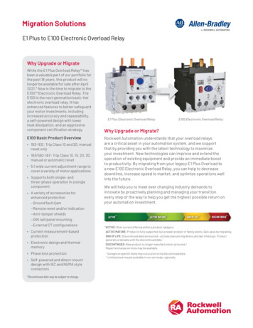
E1 Plus Overload Relay SpecificationsExternal Current Transformers (for use with cat. nos. 193-EE Z)The user shall provide one current transformer (CT) for each motor phase, and shall connect the secondary leads of the CT to the appropriateE1 Plus overload relay power terminals, as shown in the current transformer’s wiring diagrams. The CT shall have the appropriate ratio (refer to theproduct nameplate or product description). Additionally, the CT shall be selected to be capable of providing the required VA to the secondary load,which includes the E1 Plus overload relay burden at the rated secondary current and the wiring burden. Finally, the CT shall be rated for protectiverelaying to accommodate the high inrush currents associated with motor startup, and shall have an accuracy of 2% over its normal operatingrange. Typical CT ratings include (Instrument Transformers, Inc. — Model #23 or equivalent):ANSI (USA)Class C5B0.1CSA (Canada)Class 10L5IEC (Europe)5 VA Class 5P10Wiring SchematicsFigure 1 - Typical Wiring for 1-Phase IEC ApplicationsS.C.P.D.Connection must befitted by userA1L1L2L313A2149596T19798T2Connection must befitted by userT3T1T2Figure 2 - Typical Wiring for 3-Phase IEC on must befitted by user10T298T3T2T1T3Rockwell Automation Publication 193-TD011B-EN-P - January 2017
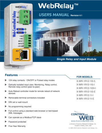
E1 Plus Overload Relay SpecificationsFigure 3 - Typical Wiring for NEMA ion must befitted by userTrip CurvesTypical reset time for 193-EE devices set to automatic reset mode is 120 seconds.Figure 4 - Trip Class 10Figure 5 - Trip Class 15Trip Class 1510001000100100Time (seconds)Time (seconds)Trip Class 101011010.10.11101FLA Multiple10FLA MultipleFigure 6 - Trip Class 20Rockwell Automation Publication 193-TD011B-EN-P - January 201711
E1 Plus Overload Relay SpecificationsFigure 7 - Trip Class 30Trip Class 20Trip Class 3010001000100Time (seconds)Time (seconds)1001010110.1110FLA Multiple0.1110FLA Multiple12Rockwell Automation Publication 193-TD011B-EN-P - January 2017
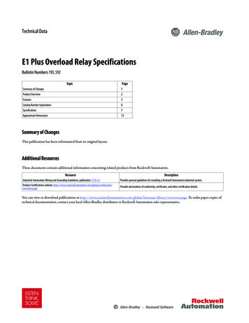
E1 Plus Overload Relay SpecificationsApproximate DimensionsApproximate dimensions are shown in millimeters (inches). Dimensions are not to be used for manufacturing purposes.Figure 8 - E1 Plus Pass-thru .31(58.6)1.97(50)1.44(36.7)0.18 ø(ø 4.5)Rockwell Automation Publication 193-TD011B-EN-P - January 201713
E1 Plus Overload Relay SpecificationsFigure 9 - Bulletin 100-C Contactor MountedAFH2DH1BE2TO RESET FROMCONTACTORMOUNTING HOLEE1TO RESET FROMCONTACTORMOUNTING HOLE2 T16 T34 T2COverload Cat. No.Contactor Cat. No.Width AHeight BDepth CDE1E2FH1H2193-ED B193-EE B193R-EE B193S-EE B100-C09, -C12, -C16, -C2345(1-25/32)146.6(5-25/32)85.2(3-23/64)4.5 (3/16)13.9 (35/64)24.5 (31/32)86.5(3-13/32)60(2-23/64)35(1-3/8)193-EE D193R-EE D193S-EE D100-C30, -C3745(1-25/32146.6(5-25/32)101.2(3-63/64)4.5 (3/16)13.9 (35/64)24.5 (31/32)104(4-3/32)60(2-23/64)35(1-3/8)193-EE D193R-EE D193S-EE D100-C4354 (2-1/8)146.6(5-25/32)101.2(3-63/64)4.5 (3/16)18.9 (3/4)24.5 (31/32)104(4-3/32)60(2-23/64)45(1-25/32)193-EE E193R-EE E193S-EE E100-C60, -C72,-C8572(2-53/64)192.3(7-37/64)120.4 (4-3/4)5.4 (7/32)23.8 /64)14Rockwell Automation Publication 193-TD011B-EN-P - January 2017
E1 Plus Overload Relay SpecificationsFigure 10 - Bulletin 100-D Contactor MountedAGDE1FCLHE2B1BKJøMCHeight BOverloadCat. No.Contactor Cat. No.Width A193-EE F100-D95, -D110193-EE FDepth CWithoutTerminalCoversWith TerminalCoversHeight 140, -D180120(4.72)339.8(13.38)418(16.46)193-EE G100-D210, -D250, -D300, -D420155(6.10)385.8(15.19)193-EE H100-D630, -D860255(10.04)552(21.73)OverloadCat. No.Contactor Cat. No.FGHJKøM193-EE F100-D95, 88)8 - 5.6(8 - 0.22)193-EE F100-D140, 8)8 - 5.6(8 - 0.22)193-EE G100-D210, -D250, -D300, -D42054 (2-1/8)130(5.12)180(7.09)140(5.51)23.5(0.93)8 - 6.5(8 - 0.26)193-EE H100-D630, )8 - 13(8 - 10.66)3.6(0.14)384.1(15.12)(Reset)Rockwell Automation Publication 193-TD011B-EN-P - January 201715
E1 Plus Overload Relay SpecificationsFigure 11 - Panel Adapter MountedAL1L3L2153H3H1BJE22 T14 T2F6 T3E1CDH2Panel AdapterCat. No.Overload Cat.No.Width AHeight BDepth CDE1E2FH1H2H3J193-EPB193-ED B193-EE B193R-EE B193S-EE B45(1-25/32116.5(4-19/16)92.7(3-21/32)4.4 (11/64)11.4(0.45)57.9(2-9/32)62.5(2-15/32)95 -EE D193R-EE D193S-EE D45(1-25/32112.4(4-7/16)108.7(4-9/32)4.4 (11/64)11.4(0.45)57.9(2-9/32)62.5(2-15/32)95 -EE E193R-EE E193S-EE E72(2-53/64)107.4(4-15/64)127 (5/32)5.5 /64)60(2-23/64)—43.3(1-45/64)16Rockwell Automation Publication 193-TD011B-EN-P - January 2017
E1 Plus Overload Relay SpecificationsNotes:Rockwell Automation Publication 193-TD011B-EN-P - January 201717
Rockwell Automation SupportUse the following resources to access support information.Knowledgebase Articles, How-to Videos, FAQs, Chat, UserForums, and Product Notification cate the phone number for your get-support-now.pageDirect Dial CodesFind the Direct Dial Code for your product. Use the code toroute your call directly to a technical support /direct-dial.pageLiterature LibraryInstallation Instructions, Manuals, Brochures, andTechnical Data.www.rockwellautomation.com/literatureGet help determining how products interact, checkfeatures and capabilities, and find associated /pcdc.pageTechnical Support CenterLocal Technical Support Phone NumbersProduct Compatibility and Download Center(PCDC)Documentation FeedbackYour comments will help us serve your documentation needs better. If you have any suggestions on how to improve this document, complete theHow Are We Doing? form at s/literature/documents/du/ra-du002 -en-e.pdf.Rockwell Automation maintains current product environmental information on its website at ental-compliance.page.Allen-Bradley, ControlLogix, E1 Plus, Rockwell Software, Rockwell Automation, and LISTEN. THINK. SOLVE are trademarks of Rockwell Automation, Inc.Trademarks not belonging to Rockwell Automation are property of their respective companies.Rockwell Otomasyon Ticaret A.Ş., Kar Plaza İş Merkezi E Blok Kat:6 34752 İçerenköy, İstanbul, Tel: 90 (216) 5698400Publication 193-TD011B-EN-P - January 2017Supersedes Publication 193-TD011A-EN-P - August 2014Copyright 2017 Rockwell Automation, Inc. All rights reserved. Printed in the U.S.A.
2 Rockwell Automation Publication 193-TD011B-EN-P - January 2017 E1 Plus Overload Relay Specifications Product Overview Standards Compliance IEC/EN 60947-4-1 IEC/EN 60947-5-1 CSA 22.2 No. 14 UL 508 Certifications CE cULus Listed C-Tick CCC Bulletin 193-ED 193-EE Type E1 Plus Electronic Overload Relay E1 Plus Electronic Overload Relay .