Transcription
Boundary-Scan Tutorial
Boundary-Scan TutorialSee the ASSET homepage on the World Wide Web athttp://www.asset-intertech.comASSET and the ASSET logo are registered trademarks ofASSET InterTech, Inc.Windows is a registered trademark of Microsoft Corporation. 2000, ASSET InterTech, Inc. 2000, R.G. Bennettsii
Boundary-Scan TutorialTable of ContentsIntroduction . 1Chapter 1: The Motivation for Boundary-Scan Architecture . 2Chapter 2: The Principle of Boundary-Scan Architecture. 4Using the Scan Path . 5Chapter 3: IEEE 1149.1 Device Architecture. 11The Instruction Register. 12The Instructions . 13Using the Instruction Register (IR). 15Use of the “Capture 01” Mode. 17The Test Access Port (TAP) . 19The Bypass Register. 23The Identification Register . 23Use of the lsb 1 Feature . 24Boundary-Scan Register. 26Providing Boundary-Scan Cells . 29Accessing Other Core-Logic Registers. 31Chapter 4: Application at the Board Level. 32General Strategy. 32Interconnect Test Example . 33Practical Aspects of Using Boundary-Scan Technology. 37Handling Non-Boundary-Scan Clusters . 37Access to RAM Arrays . 39Other Issues of BScan-to-Non-BScan Interfacing . 40Assembling the Final Test Program. 43Tester Hardware . 44Chapter 5: Related Standards . 46Boundary-Scan Description Language (BSDL). 46What Is BSDL? . 46How BSDL is Used. 47Elements of BSDL. 47Hierarchical Scan Description Language (HSDL). 50What Is HSDL? . 50HSDL Module Statements. 51Serial Vector Format (SVF). 53What Is SVF?. 53SVF Structure . 55iii
Boundary-Scan TutorialChapter 6: Boundary-Scan Tools . 60Product Life Cycle Issues . 60Design Debug . 60Manufacturing Test . 61Field Test and Repair. 63Boundary-Scan Tools Requirements . 64Design Debug . 65Manufacturing Test . 66Field Test and Repair. 70Chapter 7: Conclusion . 71Bibliography. 72Reference . 72iv
Boundary-Scan TutorialTable of FiguresFigure 1: ICT vs. Functional Test . 2Figure 2: Principle of Boundary-Scan Architecture. 4Figure 3: Using the Boundary-Scan Path . 5Figure 4: Basic Boundary-Scan Cell. 7Figure 5: Bed-of-Nails Fault Coverage . 8Figure 6: Boundary-Scan Fault Coverage (Intest). 9Figure 7: Boundary-Scan Fault Coverage (Extest). 10Figure 8: IEEE 1149.1 Chip Architecture. 11Figure 9: The Instruction Register . 12Figure 10: Using the Instruction Register — Step 1 . 15Figure 11: Using the Instruction Register — Step 3 . 17Figure 12: TAP Controller Global View. 20Figure 13: TAP Controller State Table Diagram. 21Figure 14: The Bypass Register . 23Figure 15: Device Identification Code Structure . 24Figure 16: Use of the lsb 1 Feature — Step 1. 25Figure 17: Use of the lsb 1 Feature — Step 3. 26Figure 18: Basic Boundary-Scan Cell (Input) . 27Figure 19: Basic Boundary-Scan Cell (Input/Output) . 28Figure 20: A Reason for the Hold State. 28Figure 21: Control of Tristate Outputs . 30Figure 22: Bidirectional Input/Output Pins . 30Figure 23: Interconnect Testing Example. 33Figure 24: Interconnect Testing Solution. 34Figure 25: Detecting the Fault . 35Figure 26: Locating the Fault. 37Figure 27. Handling Non-BScan Clusters. 38Figure 28. Testing a RAM Array Via Boundary Scan . 39Figure 29. BScan-to-non-BScan Interface . 40Figure 30. Assembling a Test Program: Tool Flow . 43Figure 31. Tester Hardware . 45v
Boundary-Scan Tutorialvi
Boundary-Scan TutorialIntroductionIn this tutorial, you will learn the basic elements ofboundary-scan architecture — where it came from, whatproblem it solves, and the implications on the design of anintegrated-circuit device. This tutorial also provides anoverview of the data standards applicable to the boundaryscan architecture and an overview of the software toolsavailable to perform boundary-scan-based tests.The core reference is the standard:IEEE Standard 1149.1-1990 “Test Access Port andBoundary-Scan Architecture,” available from theIEEE, 445 Hoes Lane, PO Box 1331, Piscataway,New Jersey 08855-1331, USA.The standard was revised in 1993 and again in 1994. Youcan also obtain a copy of the standard via the WWW on theIEEE home page at: http://standards.ieee.org/catalog.The 1993 revision to the standard, referred to as “1149.1a,”contained many clarifications, corrections, and minorenhancements. Two new instructions were introduced in1149.1a and these are described in this tutorial.The 1994 supplement contains a description of theBoundary-Scan Description Language (BSDL).For further, more recent publications on the boundary-scanarchitecture, see the Bibliography at the end of this tutorial.1
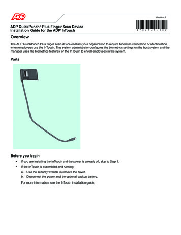
Boundary-Scan TutorialChapter 1: The Motivation for BoundaryScan ArchitectureSince the mid-1970s, the structural testing of loaded printedcircuit boards (PCBs) has relied very heavily on the use ofthe so-called in-circuit “bed-of-nails” technique (Figure 1).This method of testing makes use of a fixture containing abed-of-nails to access individual devices on the boardthrough test lands laid into the copper interconnect, or otherconvenient contact points. Testing then proceeds in twophases: the power-off tests followed by power-on tests.Power-off tests check the integrity of the physical contactbetween nail and the on-board access point. They thencarry out open and shorts tests based on impedancemeasurements.Figure 1: ICT vs. Functional TestPower-on tests apply stimulus to a chosen device on aboard, with an accompanying measurement of the responsefrom that device. Other devices that are electricallyconnected to the device-under-test are usually placed into asafe state (a process called “guarding”). In this way, the2
Boundary-Scan Tutorialtester is able to check the presence, orientation, andbonding of the device-under-test in place on the board.Fundamentally, the in-circuit bed-of-nails technique relies onphysical access to all devices on a board. For platedthrough-hole technology, the access is usually gained byadding test lands into the interconnects on the “B” side ofthe board — that is, the solder side of the board. The adventof onserted devices (surface mount) meant thatmanufacturers began to place components on both sides ofthe board — the “A” side and the “B” side. The smaller pitchbetween the leads of surface-mount components caused acorresponding decrease in the physical distance betweenthe interconnects. This had serious impact on the ability toplace a nail accurately onto a target test land. The wholequestion of access was further compounded by thedevelopment of multi-layer boards.Such was the situation in the mid-1980s when a group ofconcerned test engineers in a number of Europeanelectronics systems companies got together to examine theproblem and its possible solutions. The group of peoplecalled themselves the Joint European Test Action Group(JETAG). Their preferred method of solution was based onthe concept of a serial shift register around the boundary ofthe device — hence the name “boundary scan.” Later, thegroup was joined by representatives from North Americancompanies and the ‘E’ for “European” was dropped from thetitle of the organization leaving it Joint Test Action Group(JTAG). This was the organization that finally convertedtheir ideas into an international standard.3
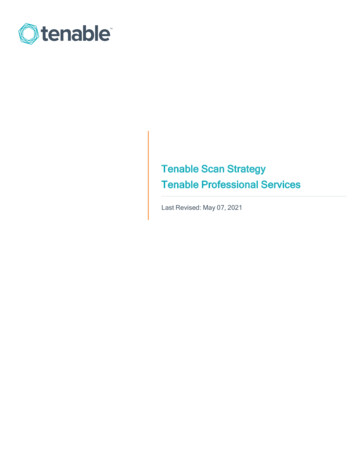
Boundary-Scan TutorialChapter 2: The Principle of Boundary-ScanArchitectureEach primary input signal and primary output signal issupplemented with a multi-purpose memory element calleda boundary-scan cell. Cells on device primary inputs arereferred to as “input cells;” cells on primary outputs arereferred to as “output cells.” “Input” and “output” is relativeto the core logic of the device. (Later, we will see that it ismore convenient to reference the terms “input” and “output”to the interconnect between two or more devices.) SeeFigure 2.Test Data In (TDI)Test Clock (TCK)Any Digital ChipTest Mode Select (TMS)Test Data Out (TDO)PISIMemoryElementPOSOEach boundary-scan cell can: Capture data on its parallel input PI Update data onto its parallel output PO Serially scan data from SO to its neighbor’s SI Behave transparently: PI passes to PO Note: all digital logic is contained inside theboundary-scan registerFigure 2: Principle of Boundary-Scan ArchitectureThe collection of boundary-scan cells is configured into aparallel-in, parallel-out shift register. A parallel loadoperation, called a “capture” operation, causes signal valueson device input pins to be loaded into input cells and, signalvalues passing from the core logic to device output pins tobe loaded into output cells. A parallel unload operation —4
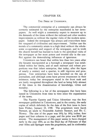
Boundary-Scan Tutorialcalled an “update” operation — causes signal valuesalready present in the output scan cells to be passed outthrough the device output pins. Signal values alreadypresent in the input scan cells will be passed into the corelogic.Data can also be shifted around the shift register, in serialmode, starting from a dedicated device input pin called“Test Data In” (TDI) and terminating at a dedicated deviceoutput pin called “Test Data Out” (TDO). The test clock,TCK, is fed in via yet another dedicated device input pin andthe mode of operation is controlled by a dedicated “TestMode Select” (TMS) serial control signal.Using the Scan PathAt the device level, the boundary-scan elements contributenothing to the functionality of the core logic. In fact, theboundary-scan path is independent of the function of thedevice. The value of the scan path is at the board level asshown in Figure 3.TDITDITCKCore LogicTDITCKCore LogicTMSTMSTDOTDOTDITDITCKCore LogicTCKCore LogicTMSTMSTDOTDOTCKTMSTDOFigure 3: Using the Boundary-Scan Path5
Boundary-Scan TutorialFigure 3 shows a board containing four boundary-scandevices. Notice that there is an edge-connector input calledTDI connected to the TDI of the first device. TDO from thefirst device is connected to TDI of the second device, and soon, creating a global scan path terminating at the edgeconnector output called TDO. TCK is connected in parallelto each device TCK input, TMS works similarly.In this way, particular tests can be applied to the deviceinterconnects via the global scan path — by loading thestimu
Testing a RAM Array Via Boundary Scan . 39 Figure 29. BScan-to-non-BScan Interface . 40 Figure 30. Assembling a Test Program: Tool Flow. 43 Figure 31. Tester Hardware . 45. Boundary-Scan Tutorial vi . Boundary-Scan Tutorial 1 Introduction In this tutorial, you will learn the basic elements of boundary-scan architecture — where it came from, what problem it solves, and the .File Size: 527KBPage Count: 78