Transcription
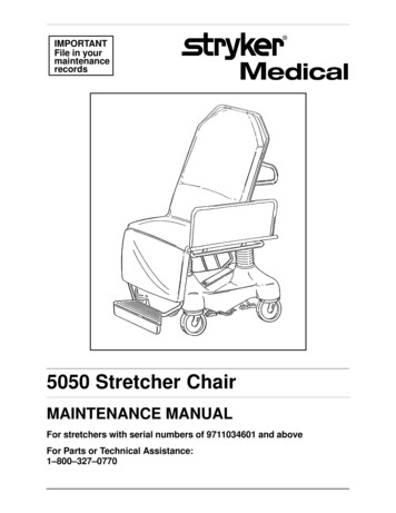
IMPORTANTFile in yourmaintenancerecords5050 Stretcher ChairMAINTENANCE MANUALFor stretchers with serial numbers of 9711034601 and aboveFor Parts or Technical Assistance:1–800–327–0770
Table of ContentsIntroductionSpecifications . . . . . . . . . . . . . . . . . . . . . . . . . . . . . . . . . . . . . . . . . . . . . . . . . . . . . . . . . . . . . . . . . . . . . . . . . . 3Warning / Caution / Note Definition . . . . . . . . . . . . . . . . . . . . . . . . . . . . . . . . . . . . . . . . . . . . . . . . . . . . . . . . 3Preventative MaintenanceChecklist . . . . . . . . . . . . . . . . . . . . . . . . . . . . . . . . . . . . . . . . . . . . . . . . . . . . . . . . . . . . . . . . . . . . . . . . . . . . . . 4Cleaning . . . . . . . . . . . . . . . . . . . . . . . . . . . . . . . . . . . . . . . . . . . . . . . . . . . . . . . . . . . . . . . . . . . . . . . . . . . . . . 4.1Service InformationHydraulic Jack Replacement . . . . . . . . . . . . . . . . . . . . . . . . . . . . . . . . . . . . . . . . . . . . . . . . . . . . . . . . . . . . . 5Jack Pump Piston Replacement . . . . . . . . . . . . . . . . . . . . . . . . . . . . . . . . . . . . . . . . . . . . . . . . . . . . . . . . 6, 7Hydraulic Check Valve ReplacementReplacement Of the Poppet Valve . . . . . . . . . . . . . . . . . . . . . . . . . . . . . . . . . . . . . . . . . . . . . . . . . . . . . 8Replacement Of the Check Valve . . . . . . . . . . . . . . . . . . . . . . . . . . . . . . . . . . . . . . . . . . . . . . . . . . . . . . 9Checking Hydraulic Fluid Level . . . . . . . . . . . . . . . . . . . . . . . . . . . . . . . . . . . . . . . . . . . . . . . . . . . . . . . . . . . 9Adjustable Pressure Compensated (P.C.) Valve Replacement . . . . . . . . . . . . . . . . . . . . . . . . . . . . . . . . 10Jack Descent Rate Adjustment . . . . . . . . . . . . . . . . . . . . . . . . . . . . . . . . . . . . . . . . . . . . . . . . . . . . . . . . . . 11Steerlock Spring Replacement . . . . . . . . . . . . . . . . . . . . . . . . . . . . . . . . . . . . . . . . . . . . . . . . . . . . . . . . . . . 11Brake/Steer Pedal Replacement . . . . . . . . . . . . . . . . . . . . . . . . . . . . . . . . . . . . . . . . . . . . . . . . . . . . . . . . . 12Siderail Adjustment . . . . . . . . . . . . . . . . . . . . . . . . . . . . . . . . . . . . . . . . . . . . . . . . . . . . . . . . . . . . . . . . . . . . 13Siderail Replacement (Transfer/Non–Transfer) . . . . . . . . . . . . . . . . . . . . . . . . . . . . . . . . . . . . . . . . . . . . . 14Dependent Leg Section Rigid Link Replacement . . . . . . . . . . . . . . . . . . . . . . . . . . . . . . . . . . . . . . . . . . . 15Foot Rest Pan Replacement (For Stationary or Adjustable Foot Rest) . . . . . . . . . . . . . . . . . . . . . . . . . 15Stationary Push Bar Replacement . . . . . . . . . . . . . . . . . . . . . . . . . . . . . . . . . . . . . . . . . . . . . . . . . . . . . . . 16Adjustable Push Bar Replacement . . . . . . . . . . . . . . . . . . . . . . . . . . . . . . . . . . . . . . . . . . . . . . . . . . . . . . . 17Pneumatic Fowler Adjustment . . . . . . . . . . . . . . . . . . . . . . . . . . . . . . . . . . . . . . . . . . . . . . . . . . . . . . . . . . . 18Independent Leg Section Cylinder Adjustment . . . . . . . . . . . . . . . . . . . . . . . . . . . . . . . . . . . . . . . . . . . . . 19Independent Leg Locking Linkage Adjustment . . . . . . . . . . . . . . . . . . . . . . . . . . . . . . . . . . . . . . . . . . . . . 20Independent Leg Section Locking Link Replacement . . . . . . . . . . . . . . . . . . . . . . . . . . . . . . . . . . . . . . . . 21Independent Leg Section Cable Replacement . . . . . . . . . . . . . . . . . . . . . . . . . . . . . . . . . . . . . . . . . . . . . 22Independent Leg Section Handle Adjustment . . . . . . . . . . . . . . . . . . . . . . . . . . . . . . . . . . . . . . . . . . . . . . 23Mattress Maintenance . . . . . . . . . . . . . . . . . . . . . . . . . . . . . . . . . . . . . . . . . . . . . . . . . . . . . . . . . . . . . . . . . . 23Caster Maintenance . . . . . . . . . . . . . . . . . . . . . . . . . . . . . . . . . . . . . . . . . . . . . . . . . . . . . . . . . . . . . . . . . . . . 24Base Lubrication Points . . . . . . . . . . . . . . . . . . . . . . . . . . . . . . . . . . . . . . . . . . . . . . . . . . . . . . . . . . . . . . . . . 25Assembly Drawings and Parts ListsBase Assembly . . . . . . . . . . . . . . . . . . . . . . . . . . . . . . . . . . . . . . . . . . . . . . . . . . . . . . . . . . . . . . . . . . . . . 26–30Brake Adjuster Assembly . . . . . . . . . . . . . . . . . . . . . . . . . . . . . . . . . . . . . . . . . . . . . . . . . . . . . . . . . . . . . . . 31Brake Cam Assembly . . . . . . . . . . . . . . . . . . . . . . . . . . . . . . . . . . . . . . . . . . . . . . . . . . . . . . . . . . . . . . . . . . 32Brake Drive Link Assembly . . . . . . . . . . . . . . . . . . . . . . . . . . . . . . . . . . . . . . . . . . . . . . . . . . . . . . . . . . . . . . 32Pump Pedal Assembly . . . . . . . . . . . . . . . . . . . . . . . . . . . . . . . . . . . . . . . . . . . . . . . . . . . . . . . . . . . . . . . . . 33Release Pedal Assembly, Head End . . . . . . . . . . . . . . . . . . . . . . . . . . . . . . . . . . . . . . . . . . . . . . . . . . . . . . 34Release Pedal Assembly, Foot End . . . . . . . . . . . . . . . . . . . . . . . . . . . . . . . . . . . . . . . . . . . . . . . . . . . . . . 35Foot End Brake Actuator . . . . . . . . . . . . . . . . . . . . . . . . . . . . . . . . . . . . . . . . . . . . . . . . . . . . . . . . . . . . . . . . 36Head End Brake Actuator . . . . . . . . . . . . . . . . . . . . . . . . . . . . . . . . . . . . . . . . . . . . . . . . . . . . . . . . . . . . . . . 37
Table of ContentsAssembly Drawings and Parts Lists (Continued)Caster Wheel Assembly . . . . . . . . . . . . . . . . . . . . . . . . . . . . . . . . . . . . . . . . . . . . . . . . . . . . . . . . . . . . . . . . 38Steer Caster Wheel Assembly . . . . . . . . . . . . . . . . . . . . . . . . . . . . . . . . . . . . . . . . . . . . . . . . . . . . . . . . . . . 39Molded Wheel Assembly . . . . . . . . . . . . . . . . . . . . . . . . . . . . . . . . . . . . . . . . . . . . . . . . . . . . . . . . . . . . . . . . 40Jack Assembly . . . . . . . . . . . . . . . . . . . . . . . . . . . . . . . . . . . . . . . . . . . . . . . . . . . . . . . . . . . . . . . . . . . . . . . . 41Jack Base Assembly . . . . . . . . . . . . . . . . . . . . . . . . . . . . . . . . . . . . . . . . . . . . . . . . . . . . . . . . . . . . . . . . . . . 42Base Hood/Label Assembly . . . . . . . . . . . . . . . . . . . . . . . . . . . . . . . . . . . . . . . . . . . . . . . . . . . . . . . . . . . . . 43Base Hood Graphics . . . . . . . . . . . . . . . . . . . . . . . . . . . . . . . . . . . . . . . . . . . . . . . . . . . . . . . . . . . . . . . . . . . 44Midsection Assembly . . . . . . . . . . . . . . . . . . . . . . . . . . . . . . . . . . . . . . . . . . . . . . . . . . . . . . . . . . . . . . . . . . . 45Fowler Assembly . . . . . . . . . . . . . . . . . . . . . . . . . . . . . . . . . . . . . . . . . . . . . . . . . . . . . . . . . . . . . . . . . . . 46, 47Dependent Leg/Stationary Foot Section Assembly . . . . . . . . . . . . . . . . . . . . . . . . . . . . . . . . . . . . . . 48–50Dependent Leg/Adjustable Foot Section Assembly . . . . . . . . . . . . . . . . . . . . . . . . . . . . . . . . . . . . . . 51–53Independent Leg/Stationary Foot Assembly . . . . . . . . . . . . . . . . . . . . . . . . . . . . . . . . . . . . . . . . . . . . 54–57Independent Leg/Adjustable Foot Section Assembly . . . . . . . . . . . . . . . . . . . . . . . . . . . . . . . . . . . . . 58–61Independent Leg Section Locking Link, Right . . . . . . . . . . . . . . . . . . . . . . . . . . . . . . . . . . . . . . . . . . . . . . 62Independent Leg Section Locking Link, Left . . . . . . . . . . . . . . . . . . . . . . . . . . . . . . . . . . . . . . . . . . . . . . . 63Non–Transfer Siderail Assembly . . . . . . . . . . . . . . . . . . . . . . . . . . . . . . . . . . . . . . . . . . . . . . . . . . . . . . . . . 64Transfer Siderail Assembly . . . . . . . . . . . . . . . . . . . . . . . . . . . . . . . . . . . . . . . . . . . . . . . . . . . . . . . . . . . . . . 65Board Support Assembly . . . . . . . . . . . . . . . . . . . . . . . . . . . . . . . . . . . . . . . . . . . . . . . . . . . . . . . . . . . . . . . 66Adjustable Push Bar Assembly . . . . . . . . . . . . . . . . . . . . . . . . . . . . . . . . . . . . . . . . . . . . . . . . . . . . . . . . . . 67Stationary Push Bar Assembly . . . . . . . . . . . . . . . . . . . . . . . . . . . . . . . . . . . . . . . . . . . . . . . . . . . . . . . . . . . 68Heel Stirrup Assembly . . . . . . . . . . . . . . . . . . . . . . . . . . . . . . . . . . . . . . . . . . . . . . . . . . . . . . . . . . . . . . . . . . 69Heel Stirrup Bracket Assembly . . . . . . . . . . . . . . . . . . . . . . . . . . . . . . . . . . . . . . . . . . . . . . . . . . . . . . . . . . 70Tethered I.V. Pole Assembly . . . . . . . . . . . . . . . . . . . . . . . . . . . . . . . . . . . . . . . . . . . . . . . . . . . . . . . . . . . . . 71Tethered I.V. Pole Trough Assembly . . . . . . . . . . . . . . . . . . . . . . . . . . . . . . . . . . . . . . . . . . . . . . . . . . . . . . 72Tethered I.V. Pole Assembly . . . . . . . . . . . . . . . . . . . . . . . . . . . . . . . . . . . . . . . . . . . . . . . . . . . . . . . . . . . . . 73I.V. Holder Assembly . . . . . . . . . . . . . . . . . . . . . . . . . . . . . . . . . . . . . . . . . . . . . . . . . . . . . . . . . . . . . . . . . . . 74Wrist Rest Assembly . . . . . . . . . . . . . . . . . . . . . . . . . . . . . . . . . . . . . . . . . . . . . . . . . . . . . . . . . . . . . . . . . . . 75Wrist Rest Assembly, Temporal . . . . . . . . . . . . . . . . . . . . . . . . . . . . . . . . . . . . . . . . . . . . . . . . . . . . . . . . . . 76Wrist Rest Accessory Bracket Assembly . . . . . . . . . . . . . . . . . . . . . . . . . . . . . . . . . . . . . . . . . . . . . . . . . . 77Leg Support Assembly . . . . . . . . . . . . . . . . . . . . . . . . . . . . . . . . . . . . . . . . . . . . . . . . . . . . . . . . . . . . . . . . . 78Leg Support Bracket Assembly . . . . . . . . . . . . . . . . . . . . . . . . . . . . . . . . . . . . . . . . . . . . . . . . . . . . . . . . . . 79Replacement Parts . . . . . . . . . . . . . . . . . . . . . . . . . . . . . . . . . . . . . . . . . . . . . . . . . . . . . . . . . . . . . . . . . . . . . . . . 80Limited WarrantyObtaining Parts and Service . . . . . . . . . . . . . . . . . . . . . . . . . . . . . . . . . . . . . . . . . . . . . . . . . . . . . . . . . . . . . 81Supplemental Warranty Coverage . . . . . . . . . . . . . . . . . . . . . . . . . . . . . . . . . . . . . . . . . . . . . . . . . . . . . . . . 81Return Authorization . . . . . . . . . . . . . . . . . . . . . . . . . . . . . . . . . . . . . . . . . . . . . . . . . . . . . . . . . . . . . . . . . . . 82Freight Damage Claims . . . . . . . . . . . . . . . . . . . . . . . . . . . . . . . . . . . . . . . . . . . . . . . . . . . . . . . . . . . . . . . . . 82
IntroductionINTRODUCTIONThis manual is designed to assist you with the maintenance of the model 5050 Stretcher Chair. Read it thoroughly before using the equipment or beginning any maintenance on it.SPECIFICATIONSMaximum Weight Capacity400 poundsOverall Stretcher Length/Width76”/30”Patient Surface Length/Width (Mattress)74”/24”Minimum/Maximum Stretcher Height (Floor to Litter Surface)22”/33.5”Foot Section Articulation0 to 80 Fowler Articulation0 to 90 Trendelenburg/Reverse Trendelenburg Articulation 18 /–18 WARNING / CAUTION / NOTE DEFINITIONThe words WARNING, CAUTION and NOTE carry special meanings and should be carefully reviewed.WARNINGThe personal safety of the patient or user may be involved. Disregarding this information could result in injuryto the patient or user.CAUTIONThese instructions point out special procedures or precautions that must be followed to avoid damaging theequipment.NOTEThis provides special information to make maintenance easier or important instructions clearer.WARNINGAlways apply the caster brakes when a patient is getting on or off the Stretcher Chair. Push on the StretcherChair to ensure the brakes are securely locked. Always engage the brakes unless the Stretcher Chair is beingmoved. Injury could result if the Stretcher Chair moves while a patient is getting on or off the Stretcher Chair.3
Preventative MaintenanceCHECKLISTAll fasteners secure (reference all assembly prints)Siderails move and latch properly – securing pins and screws are intactTransfer surface (optional equipment) intact and working properlyEngage brake pedal and push on the stretcher to ensure all casters lock securelyAll casters secure and swiveling properlySteer function working properlyFowler/leg articulation operating properly – adjust as necessaryTrendelenburg/Reverse Trendelenburg operating properlyNo leaks at hydraulic connectionsHydraulic jacks holding properlyHydraulic drop rate set properly. (see page 11 for procedure)Hydraulic oil level sufficient (see page 9 for procedure)Oxygen bottle holder intactNo rips or cracks in mattress cover or restraint straps – all Velcro intact and in good conditionHead and foot section bumpers intact and in good conditionLubricate where required, including the brake adjuster assembly and brake cam and the independentfoot section mechanisms (optional equipment)Accessories and mounting hardware in good condition and working properlySerial No.Completed By:4Date:
CleaningHand wash all surfaces of the stretcher with warm water and mild detergent. Dry thoroughly. DO NOTSTEAM CLEAN, PRESSURE WASH, HOSE OFF OR ULTRASONICALLY CLEAN. Using these methodsof cleaning is not recommended and may void this product’s warranty.Clean Velcro AFTER EACH USE. Saturate Velcro with disinfectant and allow disinfectant to evaporate. (Appropriate disinfectant for nylon Velcro should be determined by the hospital.)In general, when used in those concentrations recommended by the manufacturer, either phenolic type orquaternary type disinfectants can be used with Staph–Chek fabrics. Iodophor type disinfectants are not recommended for use on Staph–Chek fabrics because staining may result. The following products have beentested by the Herculite Laboratory and have been found not to have a harmful effect on Staph–Chek fabricsWHEN USED IN ACCORDANCE WITH MANUFACTURERS RECOMMENDED DILUTION.*TRADE ECOMMENDEDDILUTIONA33QuaternaryAirwick (Professional Products Division)2 ounces/gallonA33 (dry)QuaternaryAirwick (Professional Products Division)1/2 ounce/gallonBeaucoupPhenolicHuntington Laboratories1 ounce/gallonBlue ChipQuaternaryS.C. Johnson2 ounces/gallonElimstaphQuaternaryWalter G. Legge1 ounce/gallonFranklinPhenomysanF2500PhenolicPurex Corporation1 1/4 ounce/gallonFranklin SentinelQuaternaryPurex Corporation2 ounces/gallonGalahadPhenolicPuritan Churchill Chemical Company1 ounce/gallonHi–TorQuaternaryHuntington Laboratories1/2 ounce/gallonLPHPhenolicVestal Laboratories1/2 ounce/gallonMatarPhenolicHuntington Laboratories1/2 ounce/gallonOmegaQuaternaryAirwick (Professional Products Division)1/2 ounce/gallonQuantoQuaternaryHuntington Laboratories1 ounce/gallonSanikleenQuaternaryWest Chemical Products2 ounces/ gallonSanimaster IIQuaternaryService Master1 ounce/gallonVesphenePhenolicVestal Laboratories1 1/4 ounce/ gallonQuaternary Germicidal Disinfectants, used as directed, and/or Chlorine Bleach products, typically 5.25% Sodium Hypochlorite in dilutions ranging between 1 part bleach to 100 parts water, and 2 parts bleachto 100 parts water are not considered mild detergents. These products are corrosive in nature andmay cause damage to your stretcher if used improperly. If these types of products are used to cleanStryker patient handling equipment, measures must be taken to insure the stretchers are rinsed with cleanwater and thoroughly dried following cleaning. Failure to properly rinse and dry the stretchers will leave a corrosive residue on the surface of the stretcher, possibly causing premature corrosion of critical components.NOTEFailure to follow the above directions when using these types of cleaners may void this product’s warranty.REMOVAL OF IODINE COMPOUNDSThis solution may be used to remove iodine stains from mattress cover and foam footrest pad surfaces.1. Use a solution of 1–2 tablespoons Sodium Thiosulfate in a pint of warm water to clean the stained area.Clean as soon as possible after staining occurs. If stains are not immediately removed, allow solution tosoak or stand on the surface.2. Rinse surfaces which have been exposed to the solution in clear water before returning bed to service.4.1
Notes4.2
Service InformationHYDRAULIC JACK REPLACEMENTRequired Tools:3/8” WrenchStraight Screwdriver3” ExtensionNeedle–Nosed Pliers1/2” Wrench(2) 7/16” WrenchesAllen Wrench1/2’ SocketReplacement Procedure:NOTEIt requires two people to safely perform this procedure.1. Apply the Stretcher Chair brakes. Raise the litter to full up. Raise the Fowler and the siderails.2. Use a 3/8” wrench to remove the bolts in the litter support tubes above the black bellows on both endsof the litter.3. With the assistance of another person, lift the litter off the base and set it aside, taking care not to damagethe leg section linkages and other litter components.4. Push down on the jack actuator to put the jack in the full down position.5. Lift off the plastic base hood, separating the Velcro holding it to the base frame.6. Using an Allen wrench and a 1/2” wrench, remove the nylon lock nut underneath the pump piston.7. Using a straight screwdriver and pump spring compression tool (p/n 5050–500–70) compress the pumpspring and pry the pump link and socket head fastener out of the pump cylinder.CAUTIONDo not let the pump piston come out of the jack or damage may occur.8. Using a 1/2” socket and a 1/2” wrench, remove the four bolts, washers, and nuts holding the jack supportclamps to the base frame.9. Using the 1/2” socket and 1/2” wrench, remove the four bolts, washers, and nuts holding the jack baseto the base frame. (Using a 3” extension may be required). Remove the jack from the base frame.10. Reverse steps 8 and 9 to install the replacement jack.11. For head end jack only – using two 7/16” wrenches, remove the fasteners for the brake drive link andmove it to the side.12. With the pump pedal in the full–up position, insert the pump link into the pump pivot assembly and alignthe hole in the end of the pump link to the hole in the pump piston on the jack. Pull out or push in on thepump piston as required. Remove the pump link.13. Install the spring guide and grease before installing the jack spring onto the pump piston.14. Place the spring collar onto the end of the compression spring.15. Put the spring compression tool on the 1”x1” tubing with the handle to the right with the spring collar inthe recessed “U”–shaped plate. Push the entire assembly forward until it stops and tighten the knob.16. Visually align the pump piston to the center of the cut–out in the “U”–shaped plate. This will prevent pushing the pump piston in while compressing the jack spring. Continue to check the alignment while compressing the spring.17. Compress the jack spring by pulling back on the fixture handle. While doing this, use your left hand topush the upright, with the plastic sleeve, to the right. This prevents binding of the dowel pin in the slotof the fixture. Compress the jack spring until the fixture bottoms out.18. While keeping pressure on the jack spring, use your left hand to place the pump link into the pump pivotassembly and align the other end of the link to the hole in the pump piston.5
Service InformationHYDRAULIC JACK REPLACEMENT (CONTINUED)19. With pressure still on the jack spring, install the socket head cap screw through both the pump link andthe pump piston.20. Partially thread the locking nut for the socket head cap screw before taking the jack fixture off the 1”x1”tube.21. Tighten the locking nut for the socket head cap screw.22. Pump the jack fully up and lower to ensure proper operation.23. Reinstall the base hood, securing it to the Velcro.24. With the assistance of another person, place the litter back on the base.25. Use a 3/8” wrench to install the bolts in the litter support tubes above the black bellows on both ends ofthe litter.26. Pump the litter fully up and down to verify proper operation before returning the Stretcher Chair to service.JACK PUMP PISTON REPLACEMENTReplacement pump piston part # – 715–100–325Jack tool part # – 5050–500–70Required Tools:3/8” WrenchStraight ScrewdriverNeedle–Nosed Pliers1/2” WrenchAllen Wrench7/8” WrenchReplacement Procedure:NOTEIt requires two people to safely perform this procedure.1. Apply the Stretcher Chair brakes. Raise the litter to full up. Raise the Fowler and the siderails.2. Use a 3/8” wrench to remove the bolts in the litter support tubes above the black bellows on both endsof the litter.3. With the assistance of another person, lift the litter off the base and set it aside, taking care not to damagethe leg section linkages and other litter components.4. Push down on the jack actuator to put the jack in the full down position.5. Lift off the plastic base hood, separating the Velcro holding it to the base frame.6. Using an Allen wrench, and a 1/2” wrench, remove the nylon lock nut underneath the pump piston.7. Using a straight screwdriver and pump spring compression tool (p/n 5050–500–70), compress the pumpspring and pry the pump link and socket head fastener out of the pump cylinder.8. Remove the jack spring.9. Using needle–nosed pliers, remove the spring holder.10. Using a 7/8” wrench, remove the pump piston assembly and the bottom seal and discard the seal. Theremay be some slight hydraulic fluid leakage.11. Install the replacement seal into the jack base.12. Install the replacement pump piston assembly and tighten fully with a 7/8” wrench.13. For head end jack only – using two 7/16” wrenches, remove the fasteners for the brake drive link andmove it to the side.6
Service InformationJACK PUMP PISTON REPLACEMENT (CONTINUED)14. With the pump pedal in the full–up position, insert the pump link into the pump pivot assembly and alignthe hole in the end of the pump link to the hole in the pump piston on the jack. Pull out or push in on thepump piston as required. Remove the pump link.15. Install the spring guide and grease before installing the jack spring onto the pump piston.16. Place the spring collar onto the end of the compression spring.17. Install the spring compression tool onto the 1”x1” tubing with the handle to the right and capture the springcollar in the recessed “U”–shaped plate. Push the entire assembly forward until it stops and tighten theknob.18. Visually align the pump piston to the center of the cut–out in the “U”–shaped plate. This will prevent pushing the pump piston in while compressing the jack spring. Continue to check the alignment while compressing the spring.19. Compress the jack spring by pulling back on the fixture handle. While doing this, use your left hand topush the upright, with the plastic sleeve, to the right. This prevents binding of the dowel pin in the slotof the fixture. Compress the jack spring until the fixture bottoms out.20. While keeping pressure on the jack spring, use your left hand to place the pump link into the pump pivotassembly and align the other end of the link to the hole in the pump piston.21. With pressure still on the jack spring, install the socket head cap screw through both the pump link andthe pump piston.22. Partially thread the locking nut for the socket head cap screw before taking the jack fixture off the 1”x1”tube.23. Tighten the locking nut for the socket head cap screw.24. Pump the jack fully up and lower to ensure proper operation.25. Reinstall the base hood, securing it to the Velcro.26. With the assistance of another person, place the litter back on the base.27. Use a 3/8” wrench to install the bolts in the litter support tubes above the black bellows on both ends ofthe litter.28. Pump the litter fully up and lower to ensure proper operation before returning the Stretcher Chair to service.7
Service InformationHYDRAULIC VALVE REPLACEMENTRequired Tools:3/8” Open End Wrench1/2” Diameter RodStiff Wire (with bent, pointed end)Torque Wrench (with Ft. Lbs. adjust.)Small Needle Nose PliersReplacement of the Poppet Valve:WARNINGTo avoid personal injury or damage to the stretcher, remove the litter and the base hood with the assistanceof another person before beginning service on the jacks. Lower the jack rod completely to relieve the pressureon the pump piston side of the jack. This will prevent large hydraulic fluid loss and possible damage whenthe base plugs are removed.1. Remove the base plug (D) and the seal (L).2. Remove the compression spring (C).3. Using a small needle nose pliers, remove the poppet (F).4. Install the new poppet (F).5. Install the compression spring (C).6. Install the seal (L) and the base plug (D) and tighten to 10 foot–pounds torque.7. Pump up the jack to the maximum height. Apply weight and ensure the jack holds its position and thereare no hydraulic leaks before replacing the base hood and the litter.ITEMABCDEFHJKLMNPART NO.PART 0–50O–RingO–RingConical Comp. SpringBase PlugValve PlugPoppetPump Replacement Ass’yCheck ValveSealSealValve AssemblyP.C. Valve8
Service InformationHYDRAULIC VALVE REPLACEMENT (CONTINUED)Replacement of the Check Valve:NOTEIt requires two people to safely perform this procedure.WARNINGTo avoid personal injury or damage to the stretcher, always remove the litter and the base hood before beginning service on the jacks.1. Using a 3/8” open end wrench, remove square head set screws from both the head end and the foot endjack support tubes. Remove the litter top and set it aside.2. Lift off the plastic base hood, separating the Velcro holding it to the base frame.3. Lower the jack to the full down position. The actuator must be manually lowered while the appropriaterelease pedal is depressed.4. Remove the base plug (D) and the seal (L).5. Remove the valve plug (E).6. Using a stiff wire with a bent, pointed end, remove the check valve (J) and the seal (K).7. Install the seal (K) flat to the bottom of its hole with a 1/2” diameter rod.8. Install the new check valve (J) with the beveled end up (as shown in the illustration).9. Install the valve plug (E) and tighten to 10 foot–pounds torque.10. Install the seal (L) with the base plug (D) and tighten to 10 foot–pounds torque.11. Pump up the jack to the maximum height. Apply weight and ensure the jack holds its position and thereare no hydraulic leaks before replacing the base hood and the litter.CHECKING HYDRAULIC FLUID LEVELRequired Tools:3/8 Open End Wrench3/4 Open End WrenchProcedure:1. Using a 3/8 open end wrench, remove square head set screws from both head and foot end jack supporttubes. Remove litter top, taking care not to damage the leg section linkages and other litter components.2. Lift off the plastic base hood, separating the Velcro holding it to the base frame.3. Be sure there are no hydraulic leaks. If there are, jack replacement will be necessary. Lower the jackto the full down position. Using a 3/4 open end wrench, slowly turn the fill plug located on the side of thereservoir counterclockwise to allow excess system pressure to vent. Remove the fill plug.4. The hydraulic fluid should be visible at the bottom of the fill hole. If it is not, add Mobil Aero HFA hydraulicfluid (Stryker part number 2020–70–475) until the fluid is visible at the bottom of the fill hole. Replacethe fill plug.CAUTIONUse of other types of oil may damage hydraulic units.5. Replace the base hood and the litter.9
Service InformationADJUSTABLE PRESSURE COMPENSATED (P.C.) VALVE REPLACEMENTWARNINGTo avoid personal injury or damage to the stretcher, always remove the litter and the base hood before beginning service on the jacks. Lower the jack rod completely to relieve the pressure on the pump piston side ofthe jack.Required Tools:3/8” Wrench13/16” WrenchReplacement Procedure:NOTEIt requires two people to safely perform this procedure.1. Apply the Stretcher Chair brakes. Raise the litter to full up. Raise the Fowler and the siderails.2. Use a 3/8” wrench to remove the bolts in the litter support tubes above the black bellows on both endsof the litter.3. With the assistance of another person, lift the litter off the base and set it aside, taking care not to damagethe leg section linkages and other litter components.4. Push down on the jack actuator to put the jack in the full down position.5. Lift off the plastic base hood, separating the Velcro holding it to the base frame.6. Using a 13/16” wrench, remove the adjustable P.C. valve (see page 8 for part identification).7. Check for any contaminants in the valve as well as the jack base.8. Install a new P.C. valve. Moisten the O–ring seal with a little hydraulic fluid to ensure a good seal.9. Tighten the valve manually and then an additional 1/8–1/4 turn with 13/16” wrench. Do not over –tightenor damage may occur to the O–ring seal.10. Pump up the jack to the maximum height and press the release pedal to lower it to check the jack’s operation.11. Check for any hydraulic fluid leaks before replacing the base hood and litter.10
Service InformationJACK DESCENT RATE ADJUSTMENTRequired Tools:Bungee CordsAdjustment Procedure:1. Pump the litter up to full height2. Lift the base hood, separating the Velcro holding it to the base frame.3. The adjustable descent valve is located on the base of the jack and has a blue knob on the end. To adjust
Using a straight screwdriver and pump spring compression tool (p/n 5050- 500- 70) compress the pump spring and pry the pump link and socket head fastener out of the pump cylinder. CAUTION Do not let the pump piston come out of the jack or damage may occur. 8. Using a 1/2 " socket and a 1/2" wrench, remove the four bolts, washers, and .