Transcription
Assessing attenuation storage volumesfor SuDSAnthony McCloy outlines the approaches to providing SuDS attenuationvolumes, and highlights some important considerations when approachingattenuation designs or evaluations.The authorAs a floodplain has a finite volume, wemitigate by holding back the additionalvolume of runoff until floodwaters haveabated. The retention of this additionalvolume of runoff for a longer period of time isgenerally referred to by the industry as LongTerm Storage.Anthony McCloy, Managing Director ofMcCloy Consulting, is a Chartered CivilEngineer with expertise in water, hydrology,flood risk assessment and SuDS design. Hisexperience to date includes analysis ofdrainage systems using various hydraulicmodelling packages and development ofguidance for Local Authorities.The process of how attenuation storagevolumes are derived is generally not wellunderstood across the various disciplines whoare involved in the design of SuDS schemes.Many of us rely on spreadsheets, modellingsoftware, published maps and charts or ahelpful colleague to provide us with thevolumes and flow we require to facilitate ourSuDS design.As a leading specialist in the field ofsustainable drainage, Anthony has been a keytutor for the (CIRIA) National SUDS trainingworkshops since 2006 and resides on theProject Advisory Group for the SuDS Manualupdate.IntroductionTo deliver well considered and designedschemes it is important that all disciplines, notjust hydraulic modelling specialists, have abroader appreciation of the attenuationcalculation process, if only to ensure they canact as an intelligent client, or ask the rightquestions.Flooding is a primary concern across manyparts of the UK and Ireland. Whenevercatchment flows exceed the capacity of thereceiving watercourse, the excess water isconveyed or stored in the floodplain.Whenever a site is developed the rate ofrunoff from the site significantly increases. Inorder to protect the floodplain we endeavourto control runoff rates form a development tomatch that of predevelopment (Greenfieldrunoff) rates. Attenuation storage is requiredto hold back this volume of water to therequired rate.This fact sheet does not seek to rewritehydraulic manuals. However, a number ofaspects relating to the estimation of flows andvolumes for SuDS design have beenconsidered from a less-technical perspectivethan found in manuals. It is hoped that thisinformation will be understandable to a widerrange of members of the SuDS design / SuDSApproval Body (SAB) evaluation team. Itshould also provide the SAB team with anincreased understanding to assist with theHowever, as we cover a development sitewith hard surfaces we also lose the potentialfor water to percolate into the ground.Fact sheet March 2014www.susdrain.org1
assessment of uncomplicated schemes andidentify when they may need to seek furtheradvice from specialists.attenuation storage will overtop. Similarly,storage will not perform to designstandards if any part of the systembecomes blocked.Designing forexceedance or blockage is as, if not more,important as determination of exactstorage volumes. SuDS are designed to mimic naturaldrainageprocesses;thereforeanunderstanding of natural drainageprocesses should be fully appreciated bythe designer. Don’t overlook the linkage between storedvolumes of water and the other aspects ofSuDS such as water quality and amenitybenefit. Storage volume areas should bemulti-functional and should be at or nearthe surface wherever possible.The fact sheet covers the following aspects ofattenuation design: Understanding fundamentals Making allowance for interception losses Selecting an appropriate Coefficient ofvolumetric runoff (Cv) Expressing attenuation storage volumes asm3 for each m2 of developed site area Approaches to determining ion storage designofDon’t expect exact answers from thecalculation process, it is a usableapproximation that can provide acceptablesolutions for design. Most of the inputs arebased on statistics and calibration factors;therefore we can only ever achieve anapproximation of how the system will behavein reality. The results of calculations andmodelling need to be used alongsideprofessional judgement to provide the design.Prior to undertaking storage calculations it isimportant to understand a few of the basicsof attenuation design. A few pointers arenoted as follows: Water flows downhill! Levels of the site arevital and will be affected by approaches tomanaging volumes of water on the surfaceof the site. For flow rates to be attenuated /regulated, a flow control structure isrequired. This control could be an orifice, aweir or a more complex vortex flowcontrol arrangement. It’s likely to be more cost effective to storevolumes of water across the site withineach sub catchment as part of the SuDSmanagement train, thus maximising thesite potential, than storing at one locationprior to discharge. Consequently, anumber of flow controls are required tocontrol flows and provide storage volumesalong the management train. Anyonedesigningorevaluatingattenuation volumes should know what‘ball park’ volumes to expect prior to thecalculation (or evaluation). This ensuresthat gross errors or model stability issuescan be easily identified. If and when the specified design criteriafor flows and volumes are exceeded,Fact sheet March 2014www.susdrain.orgInterception lossesIt is generally considered that about 50% ofeach year’s total rainfall occurs in eventswhich are less than 5mm in depth. In anatural catchment, the first 4mm to 5mm ofrainfall is lost due to natural processes such assoakage into the topsoil, infiltration,evaporation and transpiration (combined thisis referred to as evapotranspiration); andtherefore does not result in runoff. Sourcecontrol techniques such as green roofs,permeable pavements and swales can beprovided to replicate natural catchmentprocesses.www.UKSuDS.com provides a Storageevaluation tool which can provide estimatesfor flows and volumes.2
Sub-catchments and providing attenuationstorage in various locations across the siteIn calculation terms, where Source Controlsare provided, an allowance can be made forinterception losses by reducing rainfall depthsby 5mm when deriving runoff generated (i.e.inflow to the attenuation storage calculation).Attenuation storage volumes are generallyexpressed as a single volume for the entiresite. Intuitively this has led to storage beenallocated to a single location, i.e. site control.However, to develop SuDS schemes which areaffordable and maximise the opportunity ofthe site, storage should be allocated acrossthe site within each sub-catchment. To aiddesign an updated approach is required toexpress storage volumesSelecting and appropriate coefficient ofvolumetric runoff (Cv)The specification of a runoff coefficientattempts to represent the volume of flowfrom a particular surface. For example, inmost circumstances you would anticipate lessrunoff from a grassed surface when comparedto an impermeable road or roof surface. Thisis represented through the definition of Cv,with values ranging from 0% (no runoff fromrainfall) up to 100% (all of the rainfall thatoccurs on a surface occurs as runoff).By expressing attenuation volumes in terms of‘m3‘ for each ‘m2‘ of developed area, allows amuch more flexible approach to allocatingstorage across the site rather than at a singlelocation.For example if 1 hectare of developed sitearea was calculated to require 700m3 ofattenuation storage. Then, for each 1 m2 ofdeveloped area we would provide 0.07m3,or 70 litres, or 70mm depth of storageThe ‘standard defaults’ for the Coefficient ofVolumetric Runoff (suggested by ModifiedRational Method) consider that a proportionof sub-catchment contributing runoff to thedrainage system is permeable. The ModifiedRational Method guidance coefficients are0.75 for summer and 0.84 for winterscenarios. This assumes that permeable partsof the sub-catchment will be wetter in winterand therefore produce more runoff.This change in approach, in terms of how theattenuation volumes are expressed allows for; easy allocation of storage to each subcatchment as part of design allows more flexibility during designiterations without the requirement toremodel the entire system to calculate anew volume after each design iteration a more transparent figure for evaluation bythe SAB.However, the majority of attenuation volumecalculations consider impermeable areas onlyas contributing to the drainage system.Therefore careful consideration needs to begiven to the specification of Cv, as the defaultvalues used in software packages may not beappropriate.Sewers for Adoption (7th Edition) recommendsthat a Cv of 1.0 should be used whenevercalculating runoff from impermeable surfaces(roofs and paved areas should have animpermeability of 100%). When making anapplication the designer should demonstrateto the SAB that Cv has been suitablydetermined.32The attenuation volume on a m /m basiscan be deduced by dividing the calculatedattenuation volume by the developed areaof the site (Roof areas roads areas anyother hard standing surface)There are numerous benefits from allocatingstorage at source, which include;Fact sheet March 2014www.susdrain.org3
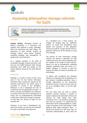
Making maximum opportunity of thestorage available on the site through theuse of existing landscape and permeablehard surfaces without the requirement ofland to be used solely for storage of flow(generally located prior to the finaldischarge point from the site) The attenuation volume requirement forthe site control is proportionally reduced Conveyance requirements are greatlyreduced Greatly reduces risk of erosion as flowrates are significantly reduced Opportunity to provide water qualitytreatment (if appropriately designed)Greenfield runoff rates are generally 3-4 timesgreater for the 1 in 100 year rainfall eventwhen compared to the 1 in 1 year rainfallevent. To capitalise on the use of the 1 in 100year Greenfield runoff allowance, long termstorage must be provided; whereby aspecified volume of water is held on site for alonger period in comparison to the attenuatedstorage volume.The application and design of Long TermStorage will be described in a follow on FactSheet.Determining attenuation storage volumesThe SuDS Manual sets out two approaches formanaging flows and volumes from adevelopment site.Provision of long term storage may not alwaysbe achievable, therefore a second approachhas been devised which attains similar resultsin terms of protection of the floodplain.The 1st approach (Approach 1) requires thatflows rates discharged from the siteattenuation storage are controlled at a rateequivalent to the runoff from a Greenfield sitefor a 1 in 1 year return period (whenever a 1in 1 year rainfall event occurs), up to theequivalent runoff from a Greenfield site for a1 in 100 year return period (whenever a 1 in100 year rainfall event occurs).The 2nd approach (Approach 2) requires thatflows from the attenuation storage arecontrolled at 1 in 2 year Greenfield runoffrate, for all rainfall events up to and includingthe 1 in 100 year rainfall return period.Figure 1 - Two approaches for managing flows and volumes from a development siteFact sheet March 2014www.susdrain.org4
There are a few aspects to consider whendetermining which approach to adopt,outlined as follows:It is important to remember that there are NOabsolute answers in the estimation of storagevolumes; however there are certain ‘ballparks’ that the calculated outcomes should bewithin. Any calculation, regardless howrefined, can only ever be an approximation ofthe actual functioning of natural system; forexample a SuDS management train whichshould perform like a natural system! Can Long Term Storage be provided on thesite to accommodate the additionalvolume of runoff generated. Approach 2 will generally result in a higheroverall storage volume for the site. Approach 2 will have longer drain-downtimes, and it may be difficult to achieve50% drain down within 24 hours. Howeverthe adoption of 24 hour half drain downtimes for design events of 1 in 100yearsplus allowances for climate change isquestionable and a more consideredapproach may be reasonable (eg. ensuringthat the drain down in 24 hours providesroom for a subsequent 1 in 10 year event).ReferencesCIRIA (2004). Sustainable drainage systems,hydraulic, structural and water qualityadvice. CIRIA Report C609.CIRIA (2007). The SuDS Manual. CIRIA ReportC697.Water UK / WRc plc (2012). Sewers forAdoption (7th Edition)SummaryHR Wallingford. www.UKsuds.comIn summary, there are a number of importantaspects to consider whenever approachingdesign or evaluation. Expressing volumes in an understandableformat such as m3 per m2 of developed sitearea, or mm depth per m2, makes theapproach to design more flexible andsimplifies the evaluation process. Runoff coefficients need to be carefullyconsidered whenever calculating runofffrom impermeable surfaces. Standarddefaults may not always be appropriate. Designing for exceedance or blockage is asimportant in design terms as definingattenuation storage volume. Design ofoutlets and flow control should ensurethat they robust, not prone to blockageand have overflows to cover any failure. The calculated storage should replicatewhat is on the drawings and what isinstalled, Levels are vital! SABs should make specificdrawing checks on levels and storage andcontinue to do so through the design andinstallation process.Fact sheet March 2014www.susdrain.orgFor further advice on designing SuDSschemes to incorporate attenuation storagein a practical cost effective way pleasecontact Anthony McCloy - 02890 848694 oremail anthony@mccloyconsulting.com5
Expressing attenuation storage volumes as m3 2for each m of developed site area Approaches to determining storage volumes Understanding the fundamentals of attenuation storage design Prior to undertaking storage calculations it is important to understand a few of the basics of attenuation