Transcription
Journal of the Illuminating Engineering SocietyISSN: 0099-4480 (Print) (Online) Journal homepage: http://www.tandfonline.com/loi/uzie20Advanced Optical Daylighting Systems: LightShelves and Light PipesL.O. Beltrán, E.S. Lee & S.E. SelkowitzTo cite this article: L.O. Beltrán, E.S. Lee & S.E. Selkowitz (1997) Advanced Optical DaylightingSystems: Light Shelves and Light Pipes, Journal of the Illuminating Engineering Society, 26:2,91-106, DOI: 10.1080/00994480.1997.10748194To link to this article: blished online: 19 Sep 2013.Submit your article to this journalArticle views: 134View related articlesCiting articles: 1 View citing articlesFull Terms & Conditions of access and use can be found tion?journalCode uzie20Download by: [Texas A&M University Libraries]Date: 13 March 2017, At: 22:02
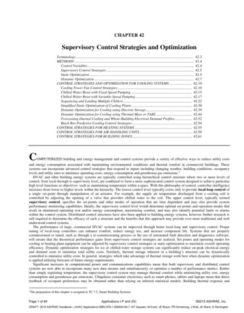
91Advanced Optical Daylighting Systems: Light Shelvesand Light PipesTHIS PAPER WAS PRESENTED ATL.O. Beltrdn, E.S. Lee, and S.E. SelkowitzIntroductionTraditional daylight designs can provide adequate day light within 4.6 m (15 ft) of the window. If daylight can beused to offset lighting energy requirements over a largerfloor area, additional energy savings can be obtained.However, the use of larger windows and higher transmittance glazings to provide sufficient levels of daylight at dis tances further from the window has proven to be ineffec tive. Daylight levels decrease asymptotically with distancefrom the window, so that a disproportionate amount ofdaylight/solar radiation must be introduced into diefront of the room to achieve small gains in daylight levelsat the back of the room. While this can increase lightingenergy savings over a larger floor area, the correspondingincrease in cooling due to solar heat gains can offset thesesavings and exacerbate peak load conditions.1 The nonuniform workplane illuminance distribution and lumi nance gradient widiin the space can also result in anuncomfortable lighting environment.In this paper, two advanced daylighting systems—lightshelves and light pipes—were designed to provide high er workplane illuminance levels deeper into the spaceover substantial daytime operating hours during the year.The two systems are presented in detail, along with themethods used for their design, daylighting, and energyconsumption evaluation. Finally, daylight and energyperformance results are presented and discussed, alongwith recommendations for further research.BackgroundThe objective of most daylighting concepts has beento control incoming direct sunlight, and minimize itspotentially negative effect on visual comfort and coolingload. Direct sunlight, however, is an excellent interiorilluminant when it is intercepted at the plane of the aper ture and efficiently distributed throughout the buildingwithout glare. Since direct sunlight contains far moreluminous energy per unit area than diffuse light fromclear or overcast skies, it requires a smaller aperture toprovide the same quantity of interior illuminance. Theplanned use of sunlight as an interior illuminant is not anew concept, but there have been few buildings wherethese concepts have been successfully demonstrated.The design of light-collecting systems relies upon thereflective and transmissive properties of the surface mate rials as well as their geometry. Developments in thin-filmcoatings provide new opportunities for the developmentLawrence Berkeley National Laboratory, Energy & EnvironmentDivision, Berkley, CA.THE 1996 IESNA ANNUAL CONFERENCEof innovative daylighting systems. The two systems pro posed here rely on highly reflective films to redirect sun light more efficiently. This study presents the furtherdevelopment of earlier prototypes2 with the addition ofside reflectors at the aperture and modified shapes toimprove the daylighting performance at more obliquesolar angles to the window. A full-scale demonstration ofthese light-redirecting concepts is documented else where.3Prototype designsThe advanced optical daylighting systems are basedon the following concepts: By reflecting sunlight to the ceiling plane, daylightcan be delivered to the workplane at depths greater thanthose achieved with conventional windows or skylights,without significant increases in daylight levels near thewindow. This redirection improves visual comfort byincreasing the uniformity of wall and ceiling luminancelevels across the depth of the room. By using a relatively small inlet glazing area andtransporting the daylight efficiently, lighting energy sav ings can be attained without severe cooling load penal ties from solar radiation. By carefully designing the system to block direct sun,direct source glare and thermal discomfort can be dimin ished. The challenge of the design stems from the largevariation in solar position and daylight availabilitythroughout the day and year.The initial design of the prototypes was completedusing computer-assisted ray-tracing calculations to deter mine the geometry of the various light-redirecting opti cal elements. The designs were tailored to utilize directFigure 1—Floor plan of light shelf designs (single level with sidereflector light shelf).JOURNAL of the Illuminating Engineering SocietyWinter 1997
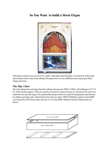
92Table 1—Summary of materials used in the light shelf designsHourly sun rays were then traced to verify thatn o reflected rays were directed downward, cre Light shelvesating direct glare. All prototypes weredesigned for Los Angeles (34 N latitude).(ft2)(ft2)(ft2))Efforts were focused o n determining the0.00.075.037.50.0Base caseo p t i m u m aperture size, reflector size, a n d0.014.837.511.287.2Single levelreflector shape to take advantage of die opti cal properties of the daylighting films a n d toSingle level w/10.088.60.0side reflectors14.837.5a c c o m m o d a t e the particular sun p a d i viewedby the window for a specific orientation a n d36.0108.00.032.060.0Bi-levelbuilding latitude. T h e light shelves a n d light24.9196.60.0Multi-level50.860.0pipes were designed to supplement the day Table 2—Glazing aperture size as a percentage of floor area of space (600 ft2) of light provided by a lower vision window a n dthe light shelf designs.to be die primary source of daylight at 4.6-9.1Light shelves Aperture size: ApertureTotal depthTotal reflectivem (15-30 ft) from the window wall. T h e lowerpercent ofheightfilmswindow employs a spectrally selective glazing,floor area(ft)(ft)(ft2)accommodates the occupant's desire for view,3.70.06.31.9Base caseprivacy, etc., a n d provides daylight u p to 4.6 m(15 ft) from die window.3.798.42.50.7Single levelExteriorglassSingle level,side Compoundreflectivefilm(ft2)White matteSurfaceLight ShelvesFour south-facing light shelf designs were2.75.3144.0Bi-level1.6developed to fit within a 0.4-1.1 m d e e p(1.5-3.75 ft deep) articulated building facade1.5221.5Multi-level8.52.5(Figures 1 a n d 2). T h e main reflector consistsof a curved, segmented surface to redirect sun light with changing solar altitudes. Each segment of thesunlight, die intensity of which is four to seven timessurface was carefully calculated, based o n the window ori greater than that of the diffuse skylight." Rays were tracedentation a n d site latitude, to ensure diat incoming raysfrom the target—located at the ceiling, 4.6-9.1 m (15-30ft) from the window—back to the reflector, for sun rays would strike die reflector at the optimal angle for redi rection into the space. T h e devices were designed to per incident over the full range of solar altitude angles. Basedform consistendy throughout the daily a n d seasonal rangeo n the required angles of the incident a n d reflected solarof solar position. T h e surface of the reflectors uses a cornrays, the o p t i m u m angle of the reflector was .6 VL3'-9"(a)3.70.7White MatteSurface5'high(lower arReflectiveFilm9" ctiveGlassSide ReflectorsCompound10'Reflective FilmhighClear Glass5' high(lower window)floor(b): - w &CompoundReflectiveFilmSpecularReflectiveFilm2'-6" highSpectrally Selective Glass10'Clear Glass highT - 4' highT(lower window)floor(d)Figure 2—Sections of light shelf designs: (a) base case light shelf, (b) single level light shelf (same section with and without side reflec tors), (c) bi-level light shelf, and (d) multi-level light shelf. Sill height is 0.91 m (3 ft).Summer 1997JOURNAL of the Illuminating Engineering Society
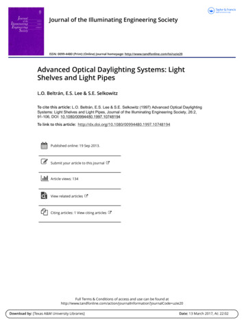
93Table 3—Summary of materials used in the light pipe design options.CollectionsectionLight pipesCross sectionat front(ft)x(ft)Base case light pipeLight Pipe ALight Pipe BLight Pipe rreflectivePrismaticfilmDiffusingfilmCross sectionat 344.355.8pound reflective film which produces two types of reflec tion: specular and narrow spread. The film is highly reflec tive (88 percent), with linear grooves that spread lightwithin an angle of 10-12 degrees at normal incidence.The light shelf designs have a variable reflector depth,and one design includes side reflectors to redirectoblique sun angles to the back of the space. A secondaryreflector with a highly reflective specular film (95 per cent) is placed above the main reflector at the ceilingplane near die window to intercept and redirect low win ter sun angles (8:00 am and 5:00 pm) onto the mainreflector. The outside aperture of all light shelf designs isrelatively small (0.2-0.7 m (0.7-2.5 ft) in section) anduses a spectrally selective glazing to minimize heat gains.The optical films used in these designs are durable, butperformance is compromised when they are scratched ormarred. The light shelves, completely sealed from theinterior and exterior environment, are protected fromdirt and occupant interference.To maximize the amount of daylight captured by themain reflector while minimizing the distance that thelight shelf projects into the room, bi-level (Figure 2c)and multi-level (Figure 2d) reflector systems were devel oped. These systems increase the glazing aperture at thewindow plane from 0.6 to 0.9 m (1.9-3 ft) and lower theheight of the view window from 1.5 to 1.2 m (5-4 ft),while reducing the depdi of the light shelf from 1.4 to 0.5m (3.8-1.5 ft). In this design, the amount of reflectorarea employing both specular and compound films hasbeen more than doubled in a slimmer, less intrusive unit(Table 1). Table 2 shows the aperture size of the lightshelf designs as a percentage of the floor space. To com2.6'Figure 3—Section of trapezoidal light pipe design (Light Pipe C).Distributionsection2x12x22x22x1pare the daylight performance of the light shelf designs,a base case light shelf (Figure 2) was defined as a 1.4 m(3.8 ft) horizontal, white matte surface located at aheight of 2.4 m (8 ft) above the floor.Light PipesThe light pipe was designed to fit within the ceilingplenum, its daylight-receiving aperture flush against theglazed spandrel of the building, so that it could be usedwith flush as well as articulated facades. This design alsohas potential as a retrofit in some existing buildings. Thelight pipe was designed to be used in combination with alower vision window. Compared to the light shelf, theoptical collector of the light pipe can be simpler indesign since the enclosed design prevents stray directsun. Additional design parameters were considered: The light pipe needed to be small enough to fit widiother building subsystems (mechanical ducts, lighting,structure, etc.) within die ceiling plenum. The cross section of the light pipe was varied to studythe changes in illumination efficiency and distribution. The reflector system needed to partially collimateincoming sunlight to minimize inter-reflections withinthe transport section of the light pipe, and to maximizethe efficiency of the system. The shape of the light pipe transport cross sectionwas altered and various reflector options were investigat ed to redirect daylight to the workplane.A total of four south-facing light pipe options wereiteratively designed and evaluated (Figures 3 and 4).Light pipe designs with different cross sections weredeveloped. The length was set at 9.1 m (30 ft), the heightwas constrained to 0.6 m (2 ft), the width of the glazingaperture was varied from 0.6 to 1.8 m (2-6 ft), and thecross section widdi was varied from 0.6 to 1.8 m (2-6 ft).A 95 percent specular reflective film was used on theinterior surfaces of the 9.1 m (30 ft) long light transportelement to redirect sunlight. The transport element wascoupled to reflectors similar to those used in the singlelevel light shelf with side reflectors. The distribution ele ment at the back end of the light pipe consists of a 4.5 mlong (15 ft) diffuser (with an 88 percent transmittance)JOURNAL of the Illuminating Engineering SocietySummer 1997
94Figure 4—Floor plans of light pipe designs: (a) base case light pipe, (b) Light Pipe A: rectangular section light pipe with central reflec tors, (c) Light Pipe B: rectangular section light pipe with side reflectors, and (d) Light Pipe C: trapezoidal section light pipe with sidereflectors (location of two light pipes in space).located at the ceiling plane. A diffusing film was used totransmit the daylight; the film has a uniform translucentappearance and is designed to maximize transmittancewith minimal back-reflectance. To maximize the overallefficiency of the light pipe and to improve overall day light distribution within die space, no daylight is trans mitted through the light pipe walls for the first 4.6 m (15ft) from the window.The first prototype, the base case light pipe (Figure4a), consisted of a single central reflector at the aperture,with a simple rectangular section in plan view and atrapezoidal section in elevation. The height narrowstoward the back end farthest from the aperture. Like thebase case, the second prototype Light Pipe A (Figure 4b)also employed one central reflector, but increased theaperture from 0.6 to 1.8 m (2-6 ft), thus creating a trape zoidal section in plan view. A constant height and there fore a rectangular section, was maintained in elevation(Table 3). The third prototype, Light Pipe B (Figure 4c),retained the same geometry as the second, but addedTable 4—Light pipe aperture size as a percentage of floor area(600 ft*).Light pipesAperture sizepercent of floor areaBase case light pipeLight Pipe ALight Pipe BLight Pipe CSummer 19970.20.92.62.6reflectors on each side of the central reflector. The pur pose of the reflectors was to improve collimation of theincoming sun rays and to reduce the number of interiorreflections within the transport pipe. In the fourth pro totype, Light Pipe C (Figure 4d), the combination of cen tral and side reflectors was retained, and the trapezoidalplan of the previous version was modified so that the rearof the unit was broadened from 0.6 to 0.9 m (2 to 3 ft) inwidth, while the rectangular section in elevation waschanged to the trapezoidal section found in the elevationof the base case light pipe. A further study was conductedusing two units of this fourth prototype side by side in thesame room. Table 4 shows the aperture size of die light 1 7 13 19 25 2 8 14 20.26 3 9 15 21 27 4 10 16 22 28 5 6 11 12 17 18 23 24 29 302.5'2.5' r20'2.5'2.5'Total reflectivefilms (ft?)115.4339.1339.8333.3JOURNAL of the Illuminating Engineering Society « — 5'5' — I« — 5'- 30'Figure 5—Plan view showing location of sensors in the IDC physi cal scale model.
95Table 5—Workplane illuminance (lux) of light shelves at 8.4 m (27.5 ft). Illuminance due to sun and sky contribution, modeled with IDCfor Los Angeles.Base case a m / p m8:00/4:009:00 y6383111127125Jun6780103118118Jul7090118134Single level a m / p 59372492May1950126275344Single level, side 6370469Apr51100212343451Bi-level a m / p -level a m / p Dec58124206337398pipe designs as a percentage of the floor area of space.Evaluation methodInitially, approximate evaluation methods were usedto gain insight into general daylight performance. Thedesign was then refined using more accurate evaluationmethods. Reduced-scale models of all prototypes werebuilt to resolve and evaluate critical daylighting, sun pen etration, and glare issues. An outdoor test was conductedto evaluate the qualitative daylight performance of eachprototype and to observe the daylight distribution andvisual characteristics of the space. Finally, experimentalmeasurements under laboratory conditions were used toobtain a more accurate daylighting performance evalua tion for all daylight hours throughout the year.The IDC method—The simulation of the annual day light performance of these optically complex systems wasaccomplished using the Integration of DirectionalCoefficients (IDC) method, which combines scale-modelphotometric measurements with analytical computerbased routines to determine daylight factors and daylightilluminance under varying sun, sky, and ground condi tions.5 Using the LBNL Scanning Radiometer, workplaneilluminance measurements were taken inside a 1:20 (0.6inches 1 ft) scale model of an office space with dimen sions of 6.1 m (20 ft) in width, 9.1 m (30 ft) in depth, and3.1 m (10 ft) in ceiling height. The interior surfacereflectances were 0.76 for the ceiling, 0.44 for the walls,and 0.21 for the floor. The window wall and ceiling of thescale model were designed to be removable so that alter nate designs of the light shelf and light pipes could bemounted and removed easily. The upper daylightingaperture was modeled to isolate the daylight contribu tion of the two prototype designs, and in combinationwith a lower window to estimate the total daylight contri bution in a typical building configuration. The lowerwindow and all the prototype apertures had a single clearglass of 0.88 visible transmittance.Workplane illuminance measurements were taken at30 interior reference points. Five parallel lines of sixcosine- and color-corrected Li-Cor photometers wereplaced in the model to measure the illuminance levels.Photometers were placed at a workplane height of 0.8 m(2.5 ft), at equal distances (0.8-8.4 m, or 2.5-27.5 ft)from the window wall, and at the centerline, 0.75 m (2.5ft), and 1.5 m (5 ft) on either side of the centerlineJOURNAL of the Illuminating Engineering SocietySummer 1997
Base case light shelfSingle level light shelfBase case light shelfSingle level light shelfSingle level w/ side red. light shelfMulti-level light shelfMulti-level light shelf ax* 0 *Base case light shelfFigure 7—Workplane illumi nance (lx) of light shelvesmodeled with die IDCmethod for Los Angeles dueto sun and sky contributionacross the space, onDecember 21 at 12:00 pm.Exterior horizontal illumi nance 53,390 lx (4960 fc).Figure 6—Workplane illumi nance (lx) of light shelvesmodeled with the IDCmethod for Los Angeles dueto sun and sky contributionacross the space, onDecember 21 at 9:00 am.Exterior horizontal illumi nance 28,590 lx (2656 fc).Single level light shelfBase case light shelfSingle level light shelfMulti-level light shelfV**Summer 1997Figure 8—Workplane illumi nance (lx) of light shelves mod eled with the IDC method forLos Angeles due to sun and skycontribution across the space,on June 21 at 9:00 am. Exteriorhorizontal illuminance 79,350be (7371 fc).JOURNAL of the Illuminating Engineering SocietyFigure 9—Workplane illumi nance (lx) of light shelvesmodeled with the IDC methodfor Los Angeles due to sunand sky contribution acrossthe space, on June 21 at 12:00pm. Exterior horizontal illumi nance 104,500 lx (9708 fc).
97Table 6—Maximum and minimum workplane illuminance (lux) and contrast gradient (CG) across the 4.6-9.1 m (15-30 ft) zone for lightshelves without lower window.CG Max./Min. woirkplane : illuminance of 15 sensor measurementsNote: Values for 3:00 pm are same as the ones for 9:00 am]BaseLight silelvesmaxcaseminCGSingle levelmaxminCGSingle levelwith side n CG12/219:00 am12:00 30812231464134302923/2K9:00 am12:00 341213236473163291516/219:00 am12:00 1620631939/219:00 am12:00 t(Figure 5). A total of 121 incoming directions of solar ical scale models, die same used for the IDC analysis,radiation at 15 degree increments, covering the whole were photographed outdoors under clear sky conditionshemisphere seen by the window, were used to create a and representative times of the year. These tests enabledcomprehensive set of directional workplane illuminance us to obtain an immediate evaluation of the efficiency ofcoefficients for each interior reference point. These the system, to visualize die amount of daylight redirec coefficients were then used in die SSG (Sun Sky and tion, to observe how direct sun penetrates the interiorGround) computer program, which mathematically inte space, and to detect the presence of specular reflectionsgrates the directional workplane illuminance coefficients or bright areas due to the optical films. Outdoor testsover the luminance distribution of the sky and the were performed on a clear sunny day, using a heliodonground, to simulate the daylight performance of die to position the physical scale model.modeled space for 168 sun positions under CIE clearFor die soudi-facing light shelves and light pipes, pho and overcast sky luminance distributions, with a uniform tographs were taken for 34 N latitude at 9:00 am, 12:00ground reflectance of 0.20.pm, and 3:00 pm on the winter and summer solsticesMultiple SSG computer runs generated a compre (June 21 and December 21) and on die equinox (Marchhensive set of sun and sky daylight factors for hourly 21 and September 21). Tests were performed for die(8:00 am to 4:00 pm) sun positions of a typical clear day upper daylighting aperture by itself and in combinationof each of die 12 mondis for latitude 34 N. These day with the lower window.light factors were converted into workplane illuminanceDOE-2 energy simulation—Energy performance evalua by multiplying each daylight factor (sun or sky) by die tion of commercial buildings is facilitated by numericalexterior horizontal sun or sky component on a clear simulation using the DOE-2.IE Building Energysunny day in Los Angeles.6Simulation Program. 7 The DOE-2 program acceptsOutdoor physical model assessment—The prototype phys- sophisticated input descriptions of die building andmechanical equipment and calculatesTable 7—Average workplane illuminance (lux) at the 4.6-9.1 m (15-30 ft) zonezone and/or building level load andfor the light shelf designs.energy use data. We performed annualNote: Values for 3:00 pm are same as the ones for 9:00 am.simulations of a prototypical floor in acommercial office building in the inlandLight shelvesBaseSingleSingle level Bi-level Multi-levelclimateof Los Angeles. The module hascaselevelw/side refl.9:00 am5512/2116680134145four perimeter zones consisting of four12:00 pm244215227387421offices, each 9.1 m (30 ft) deep by 6.1 m(20 ft) wide, surrounding a central core9:00 am65941043/211008212:00 pm131364550366385zone of 595 m 2 (6400 ft2) floor area.Floor-to-ceiling height is 3.1 m (10 ft)9:00 am2615106/211216witiia plenum of 0.8 m (2.5 ft) height.12:00 pm5719312665193Theexteriorwall resistance was fixed at9:00 am65941049/2182100Rll(U-value 0.51W / m 2 . C). Continu 12:00 pm131364550366385ous strip windows were used in the exteJOURNAL of the Illuminating Engineering SocietySummer 1997
98140-7 1203g 100a§360.& 40o Singlelevel.80oBase case:200;V-ts- " -5Single w/side refl.Bi-level;Multi level"2.5'7.5'12.5'17.5'22.5'27.5'Distance from window wall (ft)Figure 10—Daylight distribution (lx) of light shelf designs without lower window under overcast sky conditions (Exterior horizontal illu minance 19,420 lx (1804 fc)).rior wall of each perimeter zone with configurations asdescribed above (Figures 2 and 4). A clear, single-paneglazing with a visible transmittance (Tv) of 0.90, a solarheat gain coefficient (SHGC) of 0.86, and an overall Uvalue of 5.06 W/m 2 . C (0.9 Btu/ft2« F) was used for thebase case and prototypes.We simulated the daylighting performance of eachperimeter zone using continuous dimming control witha light output of 0.001 percent for a minimum powerinput of 10 percent. The design illuminance was set at538 lx (50 fc). The installed lighting power density wasset at 16.1 W/m 2 (1.5 W/ft 2 ). Using the IDC methodwithin DOE-2, daylight levels were calculated at two ref erence points in each perimeter zone at a height of 0.8m (2.5 ft) above the floor and at depths of 3.8 m (12.5 ft)and 8.4 m (27.5 ft). Each reference point controlled 50percent of the electric lights within the space.System coil loads were calculated for each perimeterzone. To isolate zone loads from the building/systeminteractions, a separate single-zone constant-volume sys Daylight performanceLight shelf results—Results from the IDC method indi cate that for an inlet aperture area of 1.4 m 2 (14.8 ft2),which represents 2.5 percent of the floor area (Table 2),the two single-level light shelf prototypes can achieveworkplane illuminance levels of over 200 lx (18.6 fc)throughout the year from 10:30 am to 1:30 pm at a dis tance of 8.4 m (27.5 ft) from the window wall, underclear sky conditions (Table 5). The single-level light shelfwith side reflectors attains 18-70 percent higher illumi-Figure 11—Photograph of single-level light shelf at equinox(March/September 21) 12:00 pm, 34 N.Figure 12—Photograph of single-level light shelf in combination withlower window at equinox (March/September 21) 12:00 pm, 34 N.Summer 1997JOURNAL of the Illuminating Engineering Societytem was assigned to each zone. A constant heating systemefficiency (0.6) and cooling system coefficient of perfor mance (3.0) converted these loads to energy usage values.Using the DOE-2.IE program, we compared lightingenergy use of the advanced optical systems to their basecase counterparts, where the lower window aperture wasnot included and the lighting controls were set to dim inthe 4.6-9.1 m (15-30 ft) area. This enabled us to isolatethe benefits of the daylighting systems alone.
99Table 8—Workplane illuminance (lux) of light pipes at 8.4 m (27.5 ft). Illuminance due to sun and sky contribution, modeled with IDCfor Los Angeles.Base case am/pm8:00 am/4:00 pm9:00 am/3:00 pm10:00 am/2:00 pm11:00 am/l:00pm12:00 v284564126213Dec264462122212Light Pipe A8:00 am/ 4:00 pm9:00 am/ 3:00 pm10:00 am/2:00 pm11:00 am/1:00 pm12:00 4823395239411428Light Pipe B8:00 am/ 4:00 pm9:00 am/ 3:00 pm10:00 am/2:00 pm11:00 am/1:00 p m12:00 0223456560571862124375345531-Light Pipe C8:00 am/4:00 pm9:00 am/3:00 pm10:00 am/2:00 pm11:00 am/1:00 pm12:00 312785786807471132705446736772-Light Pipes C8:00 am/4:00 pm9:00 am/3:00 pm10:00 am/2:00 pm11:00 am/1:00 pm12:00 62374735785705143367705741647nance levels than all the other light shelves at obliquesun azimuth angles at 9:30 am or 2:30 pm, mostly aroundthe equinox.The bi-level light shelf can achieve similar illuminancelevels to the two single-level light shelves at most times ofthe year, except during summer midday hours when illu minance levels are 25-48 percent lower than the singlelevel light shelves. The bi-level light shelf has a glazingaperture area more than twice that of the single-level and23 percent more reflector area. All the light shelf designsachieved higher workplane illuminance levels (and bet ter daylight redirection) than the base case light shelfbetween 10:00 am and 2:00 pm, but yielded lower levelsin the mornings between 8:00 and 9:00 am, and after noons between 3:00 and 4:00 pm at a distance of 8.4 m(27.5 ft) throughout the year (Table 5).Table 6 gives the maxi
Light Pipe B 6x2 24.8 15.6 315.0 0.0 44.3 2x2 Light Pipe C 6x2 24.8 15.6 308.5 0.0 55.8 2x1 Table 3—Summary of materials used in the light pipe design options. pound reflective film which produces two types of reflec tion: specular and narrow spread. The film is highly reflec tive (88 percent), with linear grooves that spread light within .