Transcription
CHAPTER 42Supervisory Control Strategies and OptimizationTerminology. 42.2METHODS . 42.4Control Variables. 42.4Supervisory Control Strategies . 42.5Static Optimization. 42.5Dynamic Optimization . 42.7CONTROL STRATEGIES AND OPTIMIZATION FOR COOLING SYSTEMS . 42.10Cooling Tower Fan Control Strategies . 42.10Chilled-Water Reset with Fixed-Speed Pumping . 42.15Chilled-Water Reset with Variable-Speed Pumping. 42.17Sequencing and Loading Multiple Chillers . 42.22Simplified Static Optimization of Cooling Plants . 42.30Dynamic Optimization for Cooling using Discrete Storage . 42.39Dynamic Optimization for Cooling using Thermal Mass or TABS . 42.44Forecasting Diurnal Cooling and Whole-Building Electrical Demand Profiles . 42.52Black Box Predictive Cooling Control Strategies . 42.54CONTROL STRATEGIES FOR HEATING SYSTEMS . 42.55CONTROL STRATEGIES FOR AIR-HANDLING UNITS . 42.59CONTROL STRATEGIES FOR BUILDING ZONES . 42.61COMPUTERIZED building and energy management and control systems provide a variety of effective ways to reduce utility costsand energy consumption associated with maintaining environmental conditions and thermal comfort in commercial buildings. Thesesystems can incorporate advanced control strategies that respond to inputs including changing weather, building conditions, occupancylevels and utility rates to minimize operating costs, energy consumption and greenhouse gas emissions.1HVAC and other building energy systems are typically controlled using hierarchical control structure where two or more levels ofcontrol, from local through to supervisory level, are combined to form a more sophisticated control system designed to achieve particularhigh level functions or objectives- such as maintaining temperature within a space. With this philosophy of control, controller intelligenceincreases from lower to higher levels within the hierarchy. The lowest control level typically exists only to provide local-loop control ofa single set-point through manipulation of an actuator. For example, the supply air temperature discharged from a cooling coil iscontrolled by adjusting the opening of a valve that provides chilled water to the coil. The upper control level, typically termedsupervisory control, specifies the set-points and other modes of operation that are time dependent and may also provide systemperformance monitoring capabilities. Ideally, the supervisory control level would determine optimal set-points and operation modes thatresult in minimized operating cost and/or energy consumption, maximizing comfort, and may also identify potential faults or alarmswithin the control system. Distributed control structures have also been applied to building energy systems, however further research isstill required to determine the efficacy of such a structure and the benefits that this approach may provide over more traditional and wellunderstood control systems.The performance of large, commercial HVAC systems can be improved through better local-loop and supervisory control. Propertuning of local-loop controllers can enhance comfort, reduce energy use, and increase component life. Systems that are properlycommissioned or tuned, such as through a re-commissioning process or the use of automated fault detection and diagnostics software,will ensure that the theoretical performance gains from supervisory control strategies are realized. Set points and operating modes forcooling or heating plant equipment can be adjusted by supervisory control strategies or static optimization to maximize overall operatingefficiency. Dynamic optimization strategies for ice or chilled-water storage systems can significantly reduce on-peak electrical energyand demand costs to minimize total utility costs. Similarly, thermal storage inherent in a building’s structure can be dynamicallycontrolled to minimize utility costs. In general, strategies which take advantage of thermal storage work best when dynamic optimizationis applied utilizing forecasts of future energy requirements.Significant increases in computational power and communications capabilities mean that both supervisory and distributed controlsystems are now able to incorporate many new data streams and simultaneously co-optimize a number of performance metrics. Ratherthan simply regulating temperature, the supervisory control system may manage thermal comfort while minimizing utility cost, energyconsumption and greenhouse gas emissions. Ubiquitous consumer electronics such as smart-phones, tablets and laptops mean that directfeedback of occupant preferences may be obtained rather than relying on inferred statistical models. Building thermal response and1The preparation of this chapter is assigned to TC 7.5, Smart Building Systems.Page 1 of 64Applications I-P and (SI) 2015 ASHRAE, Inc.DRAFT: 2015 ASHRAE Handbook—HVAC Applications ISBN 978-1-936504-94-7, NT Gayeski, M Krarti, JE Braun, PR Armstrong, J Wall, JK Ward, G Remington
42.22011 ASHRAE Handbook—HVAC Applications (I-P & SI)internal gain forecast models (learned by the controller) allow optimal start-up, night-purge and economy modes while utility interactionallows participation in demand response programs and cost reductions in demand and capacity charges.Where resources are constrained– by equipment sizing, maintenance or imposed through energy targets or demand charges– acoordinated approach to resource allocation is required to ensure an equitable balance of comfort for all building occupants. This isincreasingly likely to an important control scheme design consideration weather conditions change and as uptake of intermittentrenewable generation requires energy users to respond to this resource variability. New energy pricing models will substantially rewardusers who have this flexibility.This chapter focuses on the opportunities and control strategies associated with using supervisory control strategies and optimizationmethods applied to cooling systems, heating systems, air handling units and zone equipment. The chapter is divided into five majorsections: (1) a methods section focused on the basic principles of control systems, supervisory control strategies, static and dynamicoptimization methods; (2) applications of supervisory control and optimization to cooling systems, including cooling tower fan control,chilled water reset strategies, sequencing chillers, static optimization of cooling plant equipment, and dynamic optimization of coolingsystems with discrete thermal storage, passive thermal storage, and thermally activated building systems; (3) applications to heatingsystems and boilers; (4) applications to air handling units, including supply air temperature and static pressure reset strategies; and (5)applications to zone controls, such as night setback.TERMINOLOGYAir distribution system: includes terminal units [variable-air-volume (VAV) boxes, etc.], air-handling units (AHUs), ducts, andcontrols. In each AHU, ventilation air is mixed with return air from the zones and fed to the cooling/heating coil.Air-side economizer control: used to select between minimum and maximum ventilation air, depending on the condition of theoutdoor air relative to the conditions of the return air. Under certain outdoor air conditions, AHU dampers may be modulated to provide amixed air condition that can satisfy the cooling load without the need for mechanical cooling.Building thermal mass storage: storing energy in the form of sensible heat in building materials, interior equipment, and furnishings.Capacity: Heating or Cooling output at design or rating condition or, in certain contexts, at current operating condition.CAV systems: air-handling systems that have fixed-speed fans and provide no feedback control of airflow to the zones. Zonetemperature is controlled to a set point using a feedback controller that regulates the amount of local reheat applied to the air enteringeach zone.Charging: storing cooling capacity by removing heat from a cool storage device; or storing heating capacity by adding heat to a heatstorage device.Chilled-/hot-water/steam loop: consists of pumps, pipes, valves, and controls. Two different types of pumping systems are consideredin this chapter: primary and primary/secondary. With a primary pumping system, a single piping loop is used and water that flows throughthe chiller or boiler also flows through the cooling or heating coils. When steam is used, a steam piping loop sends steam to a hot-waterconverter, returning hot condensate back to the boiler. Another piping loop then carries hot water through the heating coils. Often, fixedspeed pumps are used with their control dedicated to chiller or boiler control. Dedicated control means that each pump is cycled on and offwith the chiller or boiler that it serves. Systems with fixed-speed pumps and two-way cooling or heating coil valves often incorporate awater bypass valve to maintain relatively constant flow rates and reduce system pressure drop and pumping costs at low loads. The valveis typically controlled to maintain a fixed pressure difference between the main supply and return lines. This set point is termed the chilledor hot-water loop differential pressure. Sometimes, primary systems use one or more variable-speed pumps to further reduce pumpingcosts at low loads. In this case, water bypass is not used and pumps are controlled directly to maintain a water loop differential pressure setpoint.Chiller or boiler plant: one or more chillers or boilers, typically arranged in parallel with dedicated pumps, provide the primarysource of cooling or heating for the system. Individual feedback controllers adjust the capacity of each chiller or boiler to maintain aspecified supply water temperature (or steam header pressure for steam boilers). Additional control variables include the number ofchillers or boilers operating and the relative loading for each. For a given total cooling or heating requirement, individual chiller or boilerloads can be controlled by using different water supply set points for constant individual flow or by adjusting individual flows foridentical set points.Chiller priority: control strategy for partial storage systems that uses the chiller to directly meet as much of the load as possible,normally by operating at full capacity most of the time. Thermal storage is used to supplement chiller operation only when the loadexceeds the chiller capacity.Condenser water loop: consists of cooling towers, pumps, piping, and controls. Cooling towers reject heat to the environment throughheat transfer and possibly evaporation (for wet towers) to the ambient air. Typically, large towers incorporate multiple cells sharing acommon sump, with individual fans having two or more speed settings. Often, a feedback controller adjusts tower fan speeds to maintaina temperature set point for water leaving the cooling tower, termed the condenser water supply temperature. Typically, condenserwater pumps are dedicated to individual chillers (i.e., each pump is cycled on and off with the chiller it serves).COP: Coefficient Of Performance is the heating or cooling output divided by electrical power input; may include CW pump and towerfan as well as compressor power (see also System COP).Demand limiting: a partial storage operating strategy that limits the capacity of the cooling system during the on-peak period. Thecooling system capacity may be limited based on its cooling capacity, its electric demand, or the facility demand.Discharge capacity: maximum rate at which cooling can be supplied from a cool storage device.Discharging: using stored cooling capacity by adding thermal energy to a cool storage device or removing thermal energy from a heatstorage device.Ice storage: types of ice storage systems include the following. An ice harvester is a machine that cyclically forms a layer of ice on asmooth cooling surface, utilizing the refrigerant inside the heat exchanger, then delivers it to a storage container by heating the surface ofthe cooling plate, normally by reversing the refrigeration process and delivering hot gases inside the heat exchanger. In ice-on-coilPage 2 of 64Applications I-P and (SI)DRAFT: 2015 ASHRAE Handbook—HVAC Applications 2011 ASHRAE, Inc.
Supervisory Control Strategies and Optimization42.3external melt, tubes or pipes (coil) are immersed in water and ice is formed on the outside of the tubes or pipes by circulating coldersecondary medium or refrigerant inside the tubing or pipes, and is melted externally by circulation the unfrozen water outside the tubes orpipes to the load. Ice-on-coil-internal melt is similar, except the ice is melted internally by circulating the same secondary coolant orrefrigerant to the load.Load leveling: a partial storage sizing strategy that minimizes storage equipment size and storage capacity. The system operates withthe refrigeration equipment running at full capacity for 24 h to meet the normal cooling minimum load profile and, when the load is lessthan the chiller output, the excess cooling is stored. When the load exceeds the chiller capacity, the additional cooling requirement isobtained from the thermal storage system.Load profile: compilation of instantaneous thermal loads over a period of time, normally 24 hours.Nominal chiller capacity: (1) chiller capacity at standard ARI (Standard 550/590) rating conditions, or (2) chiller capacity at a givenoperating condition selected for the purpose of quick chiller sizing selections.Partial storage: a cool storage sizing strategy in which only a portion of the on-peak cooling load is met from thermal storage, withthe remainder of the load being met by operating the chilling equipment.Precooling: a thermal energy storage (TES) strategy that allows a properly designed chiller system to operate more efficiently withlower condensing temperatures (low night ambient temperature) higher evaporating temperatures (60 to 69 F [15 to 20 C] chilled water)and at or near its most efficient part-load point. Precooling can be applied to the conditioned space, or directly to mass by passing chilledair or water through building elements such as concrete floor decks.Primary/secondary chilled- or hot-water systems: systems designed specifically for variable-speed pumping. In the primary loop,fixed-speed pumps provide a relatively constant flow of water to the chillers or boilers. This design ensures good chiller or boilerperformance and, for chilled-water systems, reduces the risk of freezing on evaporator tubes. The secondary loop incorporates one ormore variable-speed pumps that are controlled to maintain a water loop differential pressure set point. The primary and secondary loopsmay be separated by a heat exchanger. However, it is more common to use direct coupling with a common pipe.Storage capacity: the maximum amount of cooling (or heating) that can be achieved by the stored medium in the thermal storagedevice. Nominal storage capacity is a theoretical capacity of the thermal storage device. In many cases, this may be greater than theusable storage capacity. This measure should not be used to compare usable capacities of alternative storage systems.Storage cycle: a period (usually one day) in which a substantial charge and discharge of a thermal storage device has occurred,beginning and ending at the same state or same time of day.Storage efficiency: the ratio of useful heating or cooling extracted during the discharge cycle to that imparted to storage during thecharging cycle. One may also define an exergic efficiency that accounts for mixing and thermal destratification as well as conductionlosses.Storage inventory: the amount of usable heating or cooling capacity remaining in a thermal storage device.Storage priority: a control strategy that uses stored cooling to meet as much of the load as possible. Chillers are operated only if theload exceeds the storage system’s available cooling capacity.Supply air temperature: temperature of air leaving an AHU or package unit. The temperature supplied to the zones may differ fromthe supply air temperature due to heat transfer in the ductwork and local reheat. A local-loop controller adjusts the flow of water throughthe air handler cooling/heating coil using a two- or three-way valve to maintain a specified set-point temperature for the air downstreamof the cooling/heating coil. The value of the supply air temperature set-point will affect energy consumption and can be adjusted by thesupervisory control system.System COP: ratio of cooling rate (kWthermal) to system input power (kWelectric) required to operate all distribution fans and pumps aswell as compressors and condenser or cooling tower fans and pumps.Temperature set point: zone temperature set points are typically fixed values within the comfort zone during the occupied time, andzone humidity is allowed to “float” within a range dictated by the system design and choice of the supply air set-point temperature. Nightsetup is often used in summer to raise the zone temperature set points during unoccupied times and reduce the cooling requirements.Similarly, night setback is often used in winter to lower the zone temperature set points during unoccupied times and reduce the heatingrequirements. Setup and setbacks can also be used during occupied periods to temporarily curtail energy consumption.Thermal energy storage (TES): thermal energy storage systems are of three general types. Discrete TES uses a tank of water(usually stratified), packed bed of rock or phase-change material, or a tank of ice and water with immersed coil. Intrinsic (or passive)TES uses the thermal capacitance of the building fabric, such as concrete columns, beams and decks, or wall board, possibly augmentedby phase-change material. Thermally activated building systems (TABS) cool floors or other elements directly with embedded pipes orducts, giving storage capacity and efficiency substantially greater than can achieved by passive TES.System capacity: maximum amount of cooling that can be supplied by the entire cooling system, which may include the chillers andthe thermal storage. Usable storage capacity is the total amount of beneficial cooling able to be discharged from a thermal storagedevice. (This may be less than the nominal storage capacity, because the distribution header piping may not allow discharging the entirecooling capacity of the thermal storage device.)Total cooling load: The integrated thermal load that must be met by the cooling plant over a given period of time.VAV systems have a feedback controller that regulates the airflow to each zone to maintain zone temperature set point. The zoneairflows are regulated using dampers located in VAV boxes in each zone. VAV systems also incorporate feedback control of the primaryairflow through various means of fan capacity control. Typically, inputs to a fan outlet damper, inlet vanes, blade pitch, or variable speedmotor are adjusted to maintain a duct static pressure set point in the supply duct, as described in Chapter 47.Page 3 of 64Applications I-P and (SI)DRAFT: 2015 ASHRAE Handbook—HVAC Applications 2015 ASHRAE, Inc.
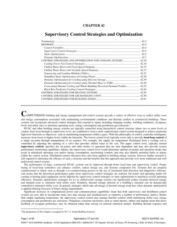
42.42011 ASHRAE Handbook—HVAC Applications (I-P & SI)METHODSCONTROL VARIABLESSystems and ControlsFigures 1 and 2 show schematics of typical centralized cooling and heating systems for which control strategies are presented in thischapter. For cooling systems, the strategies generally assume that the equipment is electrically driven and that heat is rejected to theenvironment by cooling towers. For heating systems, boilers may be fired by a variety of fuels or powered by electricity, but are typicallyfired from either natural gas or #2 or #6 fuel oil. However, some strategies apply to any type of system (e.g., return from night setup orsetback). For describing different systems and controls, it is useful to divide the system into the subsystems depicted in Figures 1 and 2:air distribution system, chilled-/hot-water loop, chiller/boiler plant, condenser water loop. A variant of the chilled-water system shown inFigure 1 uses chilled water directly for sensible cooling by radiant panels, chilled beams, or radiant floors. Similar strategies can beapplied to variable-speed controls for air-cooled chiller condenser fans.Fig. 1 Schematic of Chilled-Water Cooling SystemFig. 2 Schematic of Hot-Water Heating SystemVAV cooling system controls (Figure 1) respond to changes in building cooling requirements. As the cooling load increases, the zonetemperature rises as energy gains to the zone air increase. The zone controller responds to higher temperatures by increasing local flow ofcool air by opening a damper. Opening a damper reduces static pressure in the primary supply duct, which causes the fan controller tocreate additional airflow. With greater airflow, the supply air temperature of the cooling coils increases, which causes the air handlerfeedback controller to increase the water flow by opening the cooling coil valves. This increases the chilled-water flow and/or the chilledwater return temperature (i.e., increases the cooling load).Control of a radiant cooling system (a variant of Figure 1) responds directly to zone load by increasing the chilled-water flow rate. Thechilled-water temperature may be controlled by the neediest zone or by an open-loop control.Control of a hot-water heating system (Figure 2) is similar. As the heating load increases, the zone temperature falls as energy gains tothe zone air decrease. The zone controller responds to lower temperatures by opening a control valve and increasing the flow of hot waterthrough the local reheat coil. The supply airflow rate is usually maintained at its minimum value when a VAV system is in heating mode.Increasing water flow through the reheat coils reduces the temperature of the water returned to the boiler. With lower return watertemperature, the supply water temperature drops, which causes the feedback controller to increase the boiler firing rate to maintain thedesired supply water temperature.Page 4 of 64Applications I-P and (SI)DRAFT: 2015 ASHRAE Handbook—HVAC Applications 2011 ASHRAE, Inc.
Supervisory Control Strategies and Optimization42.5For both heating and cooling, an increase in the building load results in an increase in water flow rate, which is ultimately propagatedthrough the central system. For fixed-speed chilled- or hot-water pumps, the differential pressure controller closes the chilled- or hotwater bypass valve and keeps the overall flow relatively constant. For variable-speed pumping, the differential pressure controllerincreases pump speed. In a chilled-water system, the return water temperature and/or flow rate to the chillers increases, leading to anincrease in the chilled-water supply temperature. The chiller controller responds by increasing the chiller cooling capacity to maintainthe chilled-water supply set point (and match the cooling coil loads). The increased energy removed by the chiller increases the heatrejected to the condenser water loop, which increases the temperature of water leaving the condenser. The in-creased water temperatureentering the cooling tower increases the water temperature leaving the tower. The tower controller responds to the higher condenserwater supply temperature and increases the tower airflow. At some load, the current set of operating chillers is not sufficient to meet theload (i.e., maintain the chilled-water supply set points) and an additional chiller is brought online. For a hot-water system, the returnwater temperature and/or flow rate to the boilers decreases, leading to a decrease in the hot-water supply temperature. The boilercontroller responds by increasing the boiler heating capacity to maintain the hot-water supply set point (and match the heating coilloads).For all-electric cooling without thermal storage, minimizing power at each point in time is equivalent to minimizing energy costs.Therefore, supervisory control variables should be chosen to maximize the coefficient of performance (COP) of the system at all timeswhile meeting the building load requirements. The COP is defined as the ratio of total cooling load to total system power consumption. Inaddition to the control variables, the COP depends primarily on the cooling load and the ambient wet- and dry-bulb temperatures. Often,the cooling load is expressed in a dimensionless form as a part-load ratio (PLR), which is the cooling load under a given conditiondivided by the design cooling capacity.For cooling or heating systems with thermal storage, performance depends on the time history of charging and discharging. In thiscase, controls should minimize operating costs integrated over the billing period or storage cycle. In addition, safety features thatminimize the risk of prematurely depleting storage capacity may be important.SUPERVISORY CONTROL STRATEGIESFor any of the scenarios listed above, several local-loop controllers respond to load change to maintain specified set points. Asupervisory controller establishes modes of operation and chooses (or resets) values of set points. At any given time, cooling or heatingneeds can be met with various combinations of modes of operation and set points. This chapter discusses several methods for determiningsupervisory control variables that provide good overall performance. These methods include resetting setpoints such as chilled watersupply temperature, hot water supply temperature, supply air temperatures, differential pressure on water loops, and supply air staticpressure. Another form of supervisory control includes sequencing equipment such as chillers, boilers, pumps and fans to achieve the anenergy efficient mode of operation. Optimization methods may be applied to achieve the optimal mode of operation subject to cost,energy or comfort constraints.Sampling Intervals for Reset ControlsProper sampling intervals are required when resetting the set point for proportional-integral (PI) feedback control loops to preventoscillation of the process variable in those loops. In general, the sampling time interval between reset commands should be greater thanthe settling time for the loop. For example, resetting both the chilled-water supply temperature set point and cooling coil discharge airtemperature set point is necessary for optimal control. In this case, resetting the set points for chilled-water supply temperature andcooling coil discharge air temperature should not occur simultaneously, but at staggered intervals; the interval of reset for either loopshould be greater than the settling time for the coil (the time for the discharge air temperature of the coil to reach a new steady-statetemperature).For cascaded loops, the sampling interval between reset commands should be greater than the settling time for the slower loop. Anexample of a cascaded loop is a VAV box controller with its flow set point determined from the space temperature of its associated zone,and the box damper controlled to maintain the flow set point. For example, in resetting static pressure set point on a variable-speed airhandler fan based on VAV box damper position, the interval between resets should be greater than the settling time of the flow controlloop in a pressure-independent VAV box. (Settling time in this example is the time for the flow rate to reach a new steady-state value.)STATIC OPTIMIZATIONOptimal supervisory control of building systems involves determining the control that optimizes selected metrics such as minimizingthe total operating cost, minimizing energy consumption, or maximizing thermal comfort. Static optimization addresses the problem ofoptimizing the operation of a system at a given instant in time by operating each component of the system at the conditions which achievean optimal result, such as minimal cost. Static optimization techniques applied to a general simulation can be used to determine optimalsupervisory control variables. The simulation may be based on physical (Hiller and Glicksman 1977; Stoecker 1980) or empirical models.However, for control variable optimization, empirical and semiempirical models (where the model parameters are estimated frommeasurements) are often used. This section presents methods for static optimization useful in determining optimal control for variousapplications.General Static Optimization ProblemFigure 3 depicts the general nature of the static optimization problem for a system of interconnected components. Each component in asystem is represented as a separate set of mathematical relation
Supervisory Control Strategies and Optimization 42.3 Page 3 of 64 Applications I-P and (SI) 2015 ASHRAE, Inc. DRAFT: 2015 ASHRAE Handbook—HVAC Applications external melt, tubes or pipes (coil) are immersed in water and ice is formed on the outside of the tubes or pipes by circulating colder secondary medium or refrigerant inside the tubing or pipes, and is melted externally by circulation .