Transcription
Metropolitan Nashville – Davidson CountyStormwater Management Manual2020Table of ContentsChapter 1. 31.1How to Use This Manual . 31.2Why Green / Low Impact Development?. 41.3Brief Regulatory Background . 51.4Stormwater Management Goals. 5Chapter 2. 72.1.Design Goals / Principles . 72.2.Incentives . 8Chapter 3. 93.1Introduction . 93.2Technical Details. 11Chapter 4. 184.1 Overview . 18References. 19GIP-01 BioretentionGIP-02 Urban BioretentionGIP-03 Permeable PavementGIP-04 Infiltration TrenchesGIP-05 Water Quality SwaleGIP-06 Extended Detention PondGIP-07 Grass ChannelGIP-08 Sheet FlowGIP-09 ReforestationGIP-10 CisternGIP-11 Green RoofVolume 5 – Low Impact Development Manual1
Metropolitan Nashville – Davidson CountyStormwater Management Manual2020FiguresFigure 1 Site Planning Process. 5Figure 2 Site Example with Land Uses. 11Figure 3 Series Credit Example. 13TablesTable 1. Green Infrastructure Incentives . 8Table 2. Site Cover Runoff Coefficients. 11Table 3. Green Infrastructure Practices Runoff Reduction Credit Percentages. 12Table 4. Media Volume-Based Specifications . 15Table 5. Effectiveness of SCMs in Meeting Stormwater Management Objectives. 18Table 6. Green Stormwater Infrastructure Land Use and Land Area Selection Matrix . 19AcknowledgementMetro Water Services would like to thank the Virginia Department of Conservation and Recreation for allowingreference to their Stormwater Design Specifications and providing support in the development of this Manual.Volume 5 – Low Impact Development Manual2
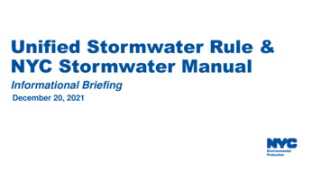
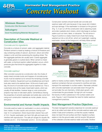
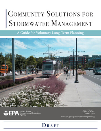
Metropolitan Nashville – Davidson CountyStormwater Management Manual2020Chapter 1INTRODUCTION1.1 How to Use This ManualThis Volume presents an introduction to Low Impact Development (LID) design and specifically Green InfrastructurePractices (GIPs) which are characterized by their ability to reduce stormwater runoff volume through the use ofinfiltration, evapotranspiration, and/or rainwater reuse. It describes how LID designs should be selected, and contains aseries of focused and concise fact sheets for each type of design. It is an addition to the Metropolitan Government ofNashville and Davidson County’s (Metro’s) Stormwater Management Manual (SWMM), which contains the followingvolumes:Volume 1 – RegulationsVolume 2 – ProceduresVolume 3 – TheoryVolume 4 – Best Management Practices (BMP)Volume 5 – Low Impact Development (LID) DesignPlease see Volume 1 for information about site development, permitting procedures, and post-construction StormwaterControl Measure (SCM) requirements. SWMM Volume 5 contains the following four chapters:Chapter 1 explains how to use this Manual, how it relates to the other volumes and why Metro is requiringLID.Chapter 2 discusses principles of site layout, current incentives to promote the use of LID and an Operationsand Maintenance overview.Chapter 3 explains the methodology surrounding runoff reduction and how it shall be applied, includingdetailed guidance on design sizing and criteria.Chapter 4 contains detailed specifications for each GIP.When planning a site, this Manual may be best used in the order shown in Figure 1, below.STEP 2Select GIP (Ch. 4)Check Runoff ReductionPercentages & size GIP (Ch. 3)STEP 3Implement GIP according toDetailed Specifications (Ch. 4)O&M Guidance (Ch. 3)STEP 1Check incentives (Ch. 2)Site Layout/Planning (Ch. 2)Figure 1 Site Planning ProcessVolume 5 – Low Impact Development Manual3
Metropolitan Nashville – Davidson CountyStormwater Management Manual20201.2 Why Green / Low Impact Development?Current development patterns and traditional stormwater management techniques have resulted in large amounts ofimpervious surfaces in cities across the country – including Metro. Conventional development approaches tostormwater management often use practices to quickly and efficiently convey water away from developed areas. Thisresults in larger volumes of runoff flowing directly to streams, rivers and combined sewer systems as well as anypollutants contained in the runoff.In contrast, LID utilizes a system of source controls and small-scale, decentralized treatment practices to help maintainthe hydrologic function of the landscape by allowing water to infiltrate, evapotranspirate or be reused onsite. Theconservation of open space, the reduction of impervious surfaces, and the use of small-scale stormwater controls, suchas green roofs, are just a few of the LID practices that can help maintain predevelopment conditions and keep greatervolumes of runoff from routing to the stormwater system. Green Infrastructure Practices (GIP), as used in this Manual,is a term that refers to a subset of LID structural systems and practices that support the principles of LID and make useof volume-reducing designs and calculations.LID techniques can offer many benefits:Municipalities Protect flora and fauna Balance growth needs with environmental protection Installation of GIPs by private sector participation at residential, commercial, and industrial facilities Decrease flooding risks for small storms Create attractive natural and multifunctional public spacesDevelopers Reduce land clearing and grading costs Potentially reduce infrastructure costs (streets, curbs, gutters, sidewalks) Reduce storm water management costs Increase lot and community marketabilityEnvironment Preserve integrity of ecological and biological systems Protect site and regional water quality by reducing sediment, nutrient, and pollutant loads to water bodies Reduce impacts to terrestrial and aquatic plants and animals Preserve trees and natural vegetation Mitigate the heat island effect and reduce energy useVolume 5 – Low Impact Development Manual4
Metropolitan Nashville – Davidson CountyStormwater Management Manual20201.3 Brief Regulatory BackgroundAs of 2016, Metro’s National Pollutant Discharge Elimination System (NPDES) Phase I Municipal Separate StormSewer System (MS4) Permit requires that new development and significant redevelopment sites utilize GIPs for postdevelopment stormwater control where possible. The design requirement is to infiltrate, evapotranspire, or capture andreuse the first inch of rain preceded by 72 hours of no measureable rainfall. Metro Water Services (MWS)commissioned this Manual to encourage and incentivize LID design in Metro before its use became a requirement. TheLID Manual was originally released in 2012, with minor revisions adopted in 2013. MWS has used the period since theManual’s release to test the methodology while the compliance path was voluntary. Where in its judgment strictapplication in a particular situation would conflict with sound engineering practice, Metro Water Services reserves theright to make exceptions to these regulations.1.4 Stormwater Management GoalsGIPs are a set of land use and structural practices designed to reduce the volume of stormwater runoff fromdevelopment through the use of the Runoff Reduction Method (RRM) employing runoff volume reducing approaches 1.The overall goal of GIPs is to reduce stormwater runoff volume and to treat pollutant loads close to the source wherethey are generated. In doing so, GIPs provide many stormwater management benefits; such as improved water quality,flow management, groundwater recharge, and channel protection. GIPs minimize the hydrological impacts of urbandevelopment on the surrounding environment by intrinsically linking stormwater management to urban design andlandscape architecture. This is accomplished with appropriate site planning and through the direction of stormwatertowards small-scale systems dispersed throughout the site. These systems should be carefully selected based on the site’stopographic and climatic conditions.GIPs have numerous benefits and advantages over conventional stormwater management. The following benefits canbe achieved by applying GIPs to new development, redevelopment, and capital improvement projects: Provide volume control and pollutant removalUnder traditional flood-focused stormwater management, the importance of volume control from smaller stormsand from the first flush of larger storms is overlooked. Reducing the amount of stormwater runoff, however, is oneof the most effective stormwater pollution controls possible. GIPs help reduce runoff volume and decrease theamount of stormwater directly entering streams and sewer systems. In addition to reducing runoff volumes,individual GIPs can help address specific pollutant removal efficiencies through settling, filtration, adsorption, andbiological uptake. By doing so, GIPs can help improve the receiving water’s aquatic and terrestrial wildlife habitatand enhance recreational uses. Recharge groundwater and stream base flowsDevelopment tends to increase imperviousness, leading to increased direct runoff and reduced rainfall infiltration.Groundwater helps feed lakes and streams, and significant reductions or loss of groundwater recharge can reducebase flow in receiving waters, negatively impacting biological habitat and recreational opportunities. Many GIPs inVolume 5 infiltrate runoff, thus promoting ground water recharge. Restore and protect stream channelsChannel erosion, on average, is estimated to account for most of the sediment load in urban watersheds and is asignificant contributor to Total Suspended Solids (TSS) issues in middle Tennessee. GIPs can help protect orreduce stream channel degradation from accelerated erosion and sedimentation during and immediately after stormevents by capturing stormwater volume and lowering stormwater peaks. By protecting stream channels, stream andriparian ecosystems have the potential to be improved and restored.Volume 5 – Low Impact Development Manual5
Metropolitan Nashville – Davidson CountyStormwater Management Manual 2020Address Combined Sewer OverflowsGIPs can be used to reduce stormwater inflows to combined sewer systems (CSS) that lead to overflows. Metro hasapproximately twelve square miles in the CSS area. Details of using green infrastructure in the CSS area are featuredin Metro’s Green Infrastructure Master Plan (MWS, 2009). Provide ancillary environmental benefitsGIPs provide additional benefits, such as improved aesthetics through the use of attractive landscaping features(trees, shrubs, and flowering plants) which can increase property values. Other benefits include increased publicawareness of stormwater management and water quality issues since practices are dispersed throughout a site andare typically more visible. GIPs such as green roofs, bioretention, and urban trees can help to mitigate the urbanheat island effect and green roofs can also decrease the energy required to heat and cool buildings.Volume 5 – Low Impact Development Manual6
Metropolitan Nashville – Davidson CountyStormwater Management Manual2020Chapter 2PLANNING, DESIGN, INCENTIVES, AND OPERATIONS AND MAINTENANCE2.1. Design Goals / PrinciplesCorrectly pairing land uses with GIPs is an important first step in site planning. GIPs should be matched with land useand setting based on the criteria found in Chapter 4. For example, low density residential development lacks largeparking areas conducive to pervious pavement with storage. However, bioretention may be especially good forresidential use.There are several important design goals and principals involved in incorporating GIPs: Achieve multiple objectivesStormwater management should be comprehensive and designed to achieve multiple stormwater objectives such as:managing peak flow and total volume; improving water quality; maintaining or improving the pre-developmenthydrologic characteristics; and maintaining water temperature. In some cases this requires multiple structuraltechniques; however, the objective of GIPs is to allow for less complex management systems to achieve multipleobjectives. Conserve natural features and resourcesThe conservation of natural features such as floodplains, soils, and vegetation helps to retain predevelopmenthydrology functions, thus reducing runoff volumes. Impacts to natural features should be minimized by reducingthe extent of construction and development practices that adversely impact predevelopment hydrology functions.This includes: Avoiding mass clearing and grading, and limiting the clearing and grading of land to the minimum neededto construct the development and associated infrastructure Leaving undisturbed stream buffers along both sides of natural streams, which is currently a Metrorequirement Preserving sensitive environmental areas, historically undisturbed vegetation, and native trees Conforming to watershed, conservation, and open space plans Designing development to fit the site terrain, and building roadways parallel to contour lines whereverpossible Clustering development and building upon the least porous soils or limiting construction activities topreviously disturbed areas to preserve porous soils and natural slopes Minimize soil compactionSoil compaction disturbs native soil structure, reduces infiltration rates, and limits root growth and plantsurvivability. When protected, local soils can have a significant infiltration capacity, and can help meet designrequirements. While soil compaction is necessary to provide structurally sound foundations, areas away fromfoundations are often excessively compacted by vehicle and foot traffic during construction. Minimizing soilcompaction can be achieved by: Reducing disturbance through design and construction practices Limiting areas of access for heavy equipment Avoiding extensive and unnecessary clearing and stockpiling of topsoil Maintaining existing topsoil and/or using quality topsoil during constructionVolume 5 – Low Impact Development Manual7
Metropolitan Nashville – Davidson CountyStormwater Management Manual 2020Manage stormwater close to the sourceRedirecting runoff back into the ground, close to the point of origin, provides both environmental and economicbenefits. Traditional stormwater systems, which collect and convey stormwater, generally increase flows and cansuffer failures over time. GIPs are used to infiltrate stormwater into the ground instead of concentrating the flowand routing it offsite. Reduce and disconnect impervious surfacesReducing and disconnecting impervious surfaces increases the rainfall that infiltrates into the ground. Imperviousareas should be reduced by maximizing landscaping and using pervious pavements. In addition, the amount ofimpervious areas hydraulically connected to impervious conveyances (e.g., driveways, walkways, culverts, streets, orstorm drains) should be reduced as much as possible. Examples include: Installing green roofs Directing roof downspouts to vegetated areas and GIPs Using permeable pavements where permitted Installing shared driveways that connect two or more homes or installing residential driveways with centervegetated strips Allowing for shared parking in commercial areas Encouraging building developers to increase their number of floors instead of their building’s footprint2.2.IncentivesCurrently offered incentives for LID offered in Metro are shown in Table 1. Please visit MWS’ Low ImpactDevelopment webpage to check for additional incentives.Table 1. Green Infrastructure IncentivesIncentiveRequirement/BenefitStormwater User Fee CreditSites designed in accordance with the LID Manual canreceive a downward adjustment in their Stormwater UserFees.Redevelopment CreditCertain previously developed sites can meet a RunoffReduction goal of 60% instead of 80%. A site must have acurrent, pre-development runoff coefficient (Rv) greaterthan 0.4 to qualify.Green Roof RebateMWS provides a credit of up to 10 per square foot ofgreen roof installed within the combined sewer system.The credit is applied to the site’s sewer bill for up to fiveyears. Please visit the MWS Stormwater Website for moreinformation.Quantity Analysis (see Chapter 3.2.5.)Volumetric GIPs can be utilized for water quantity in lieuof or in addition to traditional detention structures.Certain GIPs will also help sites earn credits under the LEED certification system. Please consult the LEEDReference Guides for more information.Volume 5 – Low Impact Development Manual8
Metropolitan Nashville – Davidson CountyStormwater Management Manual2020Chapter 3THE RUNOFF REDUCTION METHOD3.1 IntroductionThe Runoff Reduction Method (RRM) serves as the basis for Metro’s approach to GIP design. The basic RRMderivation can be found in original references.1 Runoff volume reduction is the focus of this approach; and runoffreduction equals pollution reduction. Thus, understanding and calculating every aspect of a site’s land condition inrelation to runoff reduction is important. Using the RRM, every land surface can now have an assigned rating in termsof rainfall capture. For example, if open space can infiltrate a significant rainfall event, and it can be credited with 100%TSS removal for all the rainfall it infiltrates, then the open space itself becomes an effective control. Even impervioussurfaces capture a small amount of water and therefore do not generate 100% runoff. An LID Site Design Tool hasbeen created to aid engineers in designing the water quality treatment for a project in accordance with the methodologyin the LID Manual. Please see MWS website for more information.Site drainage areas that cannot meet the runoff reduction requirement due to site limitations must be designed forpollutant removal. Please see Section 7.2 of Volume 1 for more information on site limitations. This approach focusesmainly on engineered controls to reduce stormwater pollution as runoff flows through structural controls, and requiresthat they meet an 80% removal efficiency of Total Suspended Solids (TSS). Open space land use is of only minorimportance.3.1.1ObjectivesThe basis for the RRM is a rainfall volume capture goal. In Metro the method was designed to fulfill severalcomplimentary objectives: Meet the one-inch capture requirement under the NPDES MS4 Permit; Reflect local hydrologic and land conditions; Incentivize the use of natural solutions; Provide an approach that is simple and effective for the range of development projects occurring in Metro.It was found that these objectives could be largely met through the use of a single overarching design standard, backedby specific volume-capture standards for structural controls and rainfall intensity scaled runoff coefficients for otherland uses. To be eligible for approval of a site design under this approach the designer must lay out the site such thatthe total rainfall for a one-inch event of moderate intensity is captured and treated on site through a combination ofinfiltration, evapotranspiration, harvest and/or use. This objective is accomplished through site layout and GIP design.The first step in determining if the standard is met is to determine the volumetric runoff coefficient, Rv, which is thepercentage of fallen precipitation that runs off of a specific land use area (See Equation 3.1). Rv within this methodreflects a site’s post-development runoff volume for storms in the one-inch or larger range. Based on national studiesand standards, and supported by local rainfall-runoff analysis for Nashville soils, it was found that an Rv value of 0.20generally indicates the capture of the first one-inch of rainfall. Storms larger than one inch may cause runoff.Each land use is assigned an Rv value. Once Rv values have been developed, they must be weighted for the respectiveareas. If the weighted Rv for the whole site is 0.20 or less, the standard has been met. If the Rv standard has not beenmet, GIPs consisting of intrinsic designs and structural controls devised to capture the remaining required volume are1Chesapeake Stormwater Network, CSN Tech. Bull. No. 4, “Technical Support for the Bay-Wide Runoff Reduction Method,Ver. 2.0”, (undated). and Center for Watershed Protection, “Technical Memorandum: The Runoff Reduction Method” April18th, 2008Volume 5 – Low Impact Development Manual9
Metropolitan Nashville – Davidson CountyStormwater Management Manual2020added to the design. These effectively modify the Rv value for contributing drainage areas to that intrinsic design orcontrol. These are shown in Tables 2 and 3 in Section 3.2.3.1.2Conceptual Steps in the Runoff Reduction MethodThe RRM follows the steps shown below:Step 1: Reduce Runoff Through Land Use and Ground CoverDecisions.This step focuses on the “background” land cover and how much rainfall itremoves from runoff. Design activities in Step 1 focus on impervious areaminimization, reduced soil disturbance, forest preservation, etc. The goal isto minimize impervious cover and mass site grading and to maximize theretention of forest and vegetative cover, natural areas and undisturbed soils,especially those most conducive to landscape-scale infiltration.Calculations for the RRM for Step 1 include the computation of volumetricrunoff coefficients (Rv) for land use and Hydrologic Soil Group (HSG)combinations (including impervious cover). Site cover runoff coefficientsare shown in Table 2.Step 2: Apply Environmental Site Design Practices(Non-Structural GIPs).If the target volume capture (Rv 0.20) has not been attained in Step 1then Step 2 is required. This step focuses on implementing the moreintrinsic GIPs during the early phases of site layout. In this step thedesigner enhances the ability of the background land cover to reduce runoffvolume through the planned and engineered use of such practices as sheetflow, grass channel, and reforestation. Each of these practices is assigned anability to reduce one-inch of rainfall in a storm of moderate intensity; andthis assignment is conveniently captured in the Runoff Removal Credit orthe RR Credit. RR Credit values for non-structural GIPs are shown inTable 3.Step 3: Apply Structural GIPs.If the target one-inch capture volume (Rv 0.20) has not been attained,Step 3 is required. In this step, the designer experiments with combinationsof more structural GIPs on the site. In each case, the designer estimates thearea to be treated by each GIP to incrementally meet the overall runoffreduction goal. Such engineered practices as infiltration trenches,bioretention, green roofs, permeable pavement, cisterns, etc. are envisioned.Design and sizing standards have been created for each of these GIPs toensure their ability to meet the one-inch volume capture still required afterSteps 1 and 2 have been analyzed. RR Credit values for structural GIPs arealso shown in Table 3.The guidance for the effectiveness of the various GIPs is expressed interms of percent volume reduction (Runoff Reduction Credit).At the end of Step 3, the designer must have achieved the required one-inch volume capture – which is accomplishedby attaining an area weighted Rv value of 0.20 or less. The following sections describe how to calculate Rv andassociated variables.Volume 5 – Low Impact Development Manual10
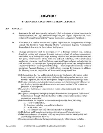
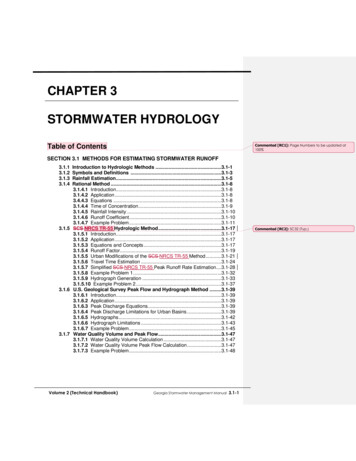
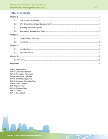
Metropolitan Nashville – Davidson CountyStormwater Management Manual20203.2 Technical Details3.2.1STEP 1: Land Use Rv ValuesThe volumetric runoff coefficient (Rv) is the ratio of the runoff divided by the target rainfall. If 45% of the rainfall for arange of storms in the one-inch range and larger is discharged from the site, the Rv value equals 0.45. Unlike a RationalMethod C Factor, for example, Rv is not a constant individual storm-based value but is rainfall intensity and total depthdependent. Rv values could be developed for individual storms, seasons, or even on an annual basis. Table 2 shows theRv values derived for Metro to estimate runoff from larger storms of moderate intensity meeting the one-inch andgreater standard.Table 2. Site Cover Runoff CoefficientsSoil ConditionVolumetric Runoff Coefficient (Rv)Impervious Cover0.95ABCDForest 0.60.60.6Hydrologic Soil GroupThese values serve as the basis for Step 1 in application of the RRM. The development of an area-weighted estimate ofthe total site Rv value using site land uses.Weighted R [(R A ) (R A ) ] (A A )Equation 3.1Figure 2 Site Example with Land UsesPreviously preserved areas or areas that cannot be developed should be excluded from the site Rv calculation. Theseareas may include, but are not limited to, water quality buffers, parkland, playgrounds, sport fields, floodway, preservedfloodplain, and slopes 33%.Volume 5 – Low Impact Development Manual11
Metropolitan Nashville – Davidson CountyStormwater Management Manual2020STEP 1 EXAMPLEAs shown in Figure 2, if we have a 10-acre site and 50% of the site was impervious, 20% forest, and 30% turfgrass all over B Soils the Rv value would be:Site Weighted Rv [(5.0*0.95) (2.0* 0.03) (3.0*0.18)]/10 0.54That is, 54% of the rainfall for the larger design storms on the site runs off. This step does not consider the flowpath of the runoff but simply the land use. The standard is the capture of the first inch and an Rv of 0.20 or lessso additional GIPs must be planned and implemented.3.2.2STEPS 2 AND 3: Green Infrastructure Practice Rv ValuesSteps 2 and 3 of the RRM involve the planning and design of Green Infrastructure Practices (both intrinsic andstructural) to reduce the total site Rv to 0.20 or less. For impervious areas draining directly to the MS4 without passingthrough water quality or quantity controls, MWS reserves the right to require treatment if a negative impact isperceived. Table 3 lists the acceptable GIPs and the assigned RR Credits for each, which corresponds with the valueslisted in each GIP specification. The two levels refer to specific design requirements contained in the specificationsheets of Chapter 4.Table 3. Green Infrastructure Practices Runoff Reduction Credit PercentagesGreen Infrastructure Practice% Rainfall Volume Removed/Captured – RRCreditLevel 1Level 21. Bioretention60802. Urban Bioretention40N/A3. Permeable Pavement40804. Infiltration Trench50905. Water Quality Swale40606. Extended Detention15N/A10/20*20/30*7. Grass Channel8. Sheet Flow9. Reforestation (A, B, C, D soils)Design dependent: 50-75*96949290989710. Rain Tanks/CisternsDesign dependent: 0-99*11. Green RoofDesign dependent: 40-90*9695* See GIP for additional information.Note that the first six GIPs themselves occupy site land area. Because of their ability to absorb the rain that falls onthem they are assigned the corresponding Forest Cover Rv values from Table 2. Other GIPs, where applicable, areassigned the Turf land cover Rv values from Table 2. The exception to this is Permeable Pavement (GIP-03), which isassigned the Rv values of 0.60 and 0.20 for Levels 1 and 2, respectively. Use of these values is optional and can beignored for the first six GIPs if their area is less than ten percent of the total site area.Volume 5 – Low Impact Development Manual12
Metropolitan Nashville – Davidson CountyStormwater Management Manual2020To calculate the Rv value for a Contributing Drainage Area (CDA) flowing through a GIP use Equation 3.2, below.GIP Rv CDA R (1 RR Credit)Equation 3.2GIP Rv equals the Contributing Drainage Area volumetric runoff coefficient as treated by the GIPs.
Stormwater Management Manual 2020 1.3 Brief Regulatory Background As of 2016, Metro's National Pollutant Discharge Elimination System (NPDES) Phase I Municipal Separate Storm Sewer System (MS4) Permit requires that new development and significant redevelopment sites utilize GIPs for post development stormwater control where possible.