Transcription
CosmicWatch: The Desktop Muon DetectorInstruction ManualMarch 10, 2018The CosmicWatch Desktop Muon Detector is a Massachusetts Institute of Technology (MIT)and National Center for Nuclear Research (NCBJ) based undergraduate-level physics projectthat incorporates various aspects of electronics-shop technical development. The desktop muondetector is a self-contained apparatus that employs plastic scintillator as a detection mediumand a silicon photomultiplier for light collection. These detectors can be battery powered andused in conjunction with the provided software to make interesting physics measurements. Datacan be recorded directly to a microSD card, to a computer, or plotted in real time on theCosmicWatch website. This document describes in detail how to build, test, and troubleshoota detector.Authors: Spencer N. Axani (saxani@mit.edu), Katarzyna Frankiewicz (katarzyna.frankiewicz@ncbj.gov.pl), andJanet M. Conrad (conrad@mit.edu)
Contents1 Document Overview42 Condensed instructions53 Instructions for building your first detector63.1Purchasing the components . . . . . . . . . . . . . . . . . . . . . . . . . . . . .63.2Uploading code to Arduino Nano . . . . . . . . . . . . . . . . . . . . . . . . . .74 Populating the PCBs94.1The SDcard PCB . . . . . . . . . . . . . . . . . . . . . . . . . . . . . . . . . . .94.2The main PCB . . . . . . . . . . . . . . . . . . . . . . . . . . . . . . . . . . . .104.3Populating the SiPM PCB . . . . . . . . . . . . . . . . . . . . . . . . . . . . . .114.4Machining the scintillator . . . . . . . . . . . . . . . . . . . . . . . . . . . . . .124.5Mounting the SiPM PCB to the scintillator. . . . . . . . . . . . . . . . . . . .134.6Assembling the Desktop Muon Detector . . . . . . . . . . . . . . . . . . . . . .145 Electronics Description5.114Description of the circuit . . . . . . . . . . . . . . . . . . . . . . . . . . . . . . .145.1.1DC-DC Booster . . . . . . . . . . . . . . . . . . . . . . . . . . . . . . . .155.1.2SiPM circuit . . . . . . . . . . . . . . . . . . . . . . . . . . . . . . . . . .165.1.3Amplifying circuit . . . . . . . . . . . . . . . . . . . . . . . . . . . . . . .175.1.4Peak detector . . . . . . . . . . . . . . . . . . . . . . . . . . . . . . . . .175.1.5microSD card circuit . . . . . . . . . . . . . . . . . . . . . . . . . . . . .185.1.6Arduino . . . . . . . . . . . . . . . . . . . . . . . . . . . . . . . . . . . .182
5.2Calibrating the electronics . . . . . . . . . . . . . . . . . . . . . . . . . . . . . .196 Recording data197 Setting the detectors up in coincidence228 Example Measurements228.1Beamline measurement at FermiLab. . . . . . . . . . . . . . . . . . . . . . . .8.2Rate measurement 1km underground at Super Kamiokande8.3Muon rate measurement at 33,000ft8.4Master/Slave mode comparison at sea level8.5Cosmic ray muon angular distribution measurement22. . . . . . . . . . .23. . . . . . . . . . . . . . . . . . . . . . . .239 Troubleshooting. . . . . . . . . . . . . . . . . . . . . . . . . . . . . . . . . .2424243
1Document OverviewCosmicWatch is an outreach program developed by MIT and NCBJ that enables students tobuild their own in-expensive cosmic ray muon detector. A single detector costs approximately100 and takes a novice high-school student approximately 4-hours to build for the first timeand a second detector can be built in under two hours. Details regarding our project can befound on the CosmicWatch website:www.cosmicwatch.lns.mit.eduThis version of the detector includes several improvements over the previous itteration. In particular, this version includes a microSD card reader/writer, updated electronics, and a connectionwhich can be used to connect multiple detectors together to make coincidence measurements.Further, we reduce the noise, improve the electronics circuit design, and update the softwarenecessary to use the detector. All suplementary marerials pertaining to this project is availablein the GitHub atch-Desktop-Muon-Detector-v2The CosmicWatch Desktop Muon Detector consists of a 5 cm 5 cm 1 cm slab of solid plasticscintillator instrumented with a silicon photomultiplier (SiPM) to detect scintillation light emitted from charged particles as they pass through the scintillator. The signal from the SiPM issent through a custom designed printed circuit board (PCB) which shapes the signal such thata micro-controller (an Arduino Nano) can measure the time and amplitude of the SiPM signal.We use an Arduino Nano to measure the pulse amplitude and record the count number, timeof the event, temperature, and detector dead time. The threshold for a signal from the SiPMto trigger the data acquisition can be adjusted in the provided Arduino software. The detectorcan be powered by a USB Mini to USB connector.There are multiple ways to read out data from the detector. The OLED screen on the frontof the detector updates every second with the count number, count rate, and a bar indicatingthe SiPM pulse amplitude of the most recent event. An LED flashes every time an eventis registered. The detector can be connected to an oscilloscope through the BNC header onthe back of the detector to view the raw SiPM pulse. We include a python based program(supplementary material: Recording data/import data.py) that allows the user to record datadirectly to the computer via a USB port, or connect directly to the webstie to plot the data inreal-time. Finally, we also provide code for recording data directly to a build-in microSD cardreader/writer.This document serves as an instruction manual for the desktop muon detector. We begin byoutlining simplified, short instructions for users who are already familiar with the basic conceptsof the detector. Then, we break it down each step into a more detailed description in which weelaboarate on how the electronics in the detector were designed, the software for operating thedetector and recording data, and provide a few example measurements. The final section can4
be used for troubleshooting.2Condensed instructionsThis section provides a concise list of recommended steps to follow. A detailed description ofeach step is provided in the subsequent section.1. Purchase all components listed in the “Purchasing List.xl.” This includes purchasing theprinted circuit boards.2. Upload the coincidence.ino code to the Arduino Nano. This requires several libraries tobe installed which are listed in the header and the README file in the Arduino directory.3. Populate all the components using the SMT reference (SMT reference.pdf) on main PCBand SDcard PCB.4. Power the detector through the Arduino and test HV pin on Main PCB to ensure it isdelivering roughly 29.5 V.5. Populate the SiPM PCB.6. Machine the scintillator to 5 5 1 cm. Drill 4 mounting holes for the SiPM PCB thenheat polish the machined surfaces.7. Wrap the plastic scintillator in a reflective foil.8. Put optical gel on SiPM and screw SiPM PCB into the plastic scintillator.9. Wrap the plastic scintillator and SiPM PCB with black electrical tape to make it lighttight.10. Plug the SiPM PCB into the Main PCB. The OLED screen will read out the rate oftriggers and the LED will flash every time the detector triggers.11. Name the detector by uploading the naming.ino Arduino code.12. Upload the OLED.ino or the SDCard.ino code to the Arduino depending on if you wantto use the OLED screen or the microSD card respectively.13. If there is a problem, see troubleshooting section (Section 9) of this document.5
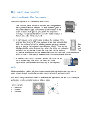
3Instructions for building your first detectorThis section contains a detailed description of the construction of one of the CosmicWatchDesktop Muon Detectors. Here, we try to elaborate on potential issues, and provide as muchinformation as possible.3.1Purchasing the componentsThe first step is to purchase the required equipment. In the GitHub repository we’ve provideda list of the components used in the project. It should be noted that it is advantageous to buildmultiple detectors, either at your institution, or in a group in order to reduce cost of purchasingsingle components. We’ve also included the price at which we purchase these items for theproject.1. Send the PCB Gerber files (PCB files/PCB Gerber files.zip), contained in the zippedPCB file, to a PCB manufacturer. The three PCBs are manufactured together and fitinside 10 cm 10 cm square. They are all two layer, and the PCB thickness should be1.6 mm in order to properly fit inside the aluminum case. A rendering of the PCBs areshown in Fig. 1. For manufacturing, we use Elecrow.com [7], from which you can ordera minimum of 5 PCBs for approximately 5 USD. We found that expedite shipping takesroughly 10 days. If you do not choose expedite shipping, manufacturing and shippingtakes approximately a month.2. Elecrow.com can also laser cut acrylic. We use this service for the colorful faceplates(see Fig. 2) on the front and back of the case. In order to laser cut the faceplates, simplyupload the “EndPlates for laser cutting.dxf.zip” file to the Elecrow.com website, select thedimensions to be 10 15 2.5 mm, and choose your desired color. Each 10 15 2.5 mmacrylic plate holds two front plates and two backplates.3. The aluminium enclosure (2506H-2.9 inch anoodized aluminium, without faceplates) canbe purchased from enclosuresandcasesinc.com [8] by providing them with the top andbottom silkscreens found in the “Enclosure Files” folder. The number 2506 represents thesplit case design of a certain size, the ’H’ is not used since we do not want the metalfaceplates, and the ’2.9 inch’ represents the lenght of the case.4. The electronic components found in the excel file can all typically be found at eitherDigikey.com [5], Ebay.com [6], or Amazon.com [4]. We also use a few components fromLinera Technology and Texas Instruments. The spreadsheet provides a link to where wepurchase our components from, but most components are generic.5. The 16 MHz Arduino Nano can be found at many local electronic shops but we prefer topurchase large orders from Ebay where they can be found for under 2.5 USD.6
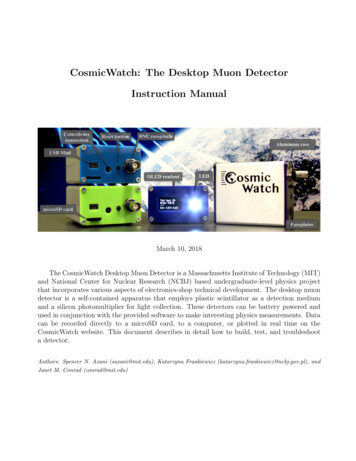
6. The SiPM can be purchased from SensL [9]. We use the SensL 60035 SMT C-series. Ithas a photocathode area of 6 mm 6 mm (36 mm2 active area). The documentation canbe found in Ref. [2]. The price per SiPM drops significantly once you place an order ofx100 or more. It is recommended to look for other groups who are making large SiPMorders and work with them. We’ve found many physics professors and research scientiststhat work with photomultipliers may be able to help you. Currently, SensL offers a specialprice (60 USD) for students here, [10]. When purchasing in quantities greater than x100,the price currently drops to 48 USD per SiPM.7. There are several companies that sell plastic scintillator, but we found that physics departments often have left over scintillator from previous experiments. We use 1 cm thickscintillator since it appears to be the most common size available and will produce a sufficient number of photons to help distinguish a muon event from a background event. Ebayand other online shops often sell used scintillator as well. The SiPM photon detectionefficiency peaks at 420 nm , therefore the scintillator should be chosen to emit near thatfrequency with the highest photon yield per MeV. We’ve found all of our scintillator invarious labs and physics departments, but have talked with people who aquire scintillatorfrom companies such as Eljen [?] or Saint-Gobain [?]. We’ve also seen scintillator of thecorrect size available on Ebay.Figure 1: A rendering of the three PCBs.3.2Uploading code to Arduino NanoBefore soldering the header pins onto the Arduino Nano, the OLED.ino (Arduino code/OLED.ino)Arduino code should be uploaded to make sure the Arduino works. First, we must install the7
Figure 2: A rendering faceplates for the aluminum enclosure.Arduino Integrated Development Environment (IDE), this will allow us to modify and upload thecode to run the Arduino. The Arduino IDE can be found here:https://www.arduinIf you are using a Mac operating system, you must also install the CH340g driver. This drivercan be installed from ’brew’ or from downloading the package from Ref. [3].It also looks like Windows users will need to install the CH340g driver.Now, lauch the Arduino IDE and install the required libraries for the code. Libraries can beinstalled directly in the IDE by clicking Sketch Include Library Manage Libraries. Fromhere, install the following libraries:1. Adafruit SSD1306 – by Adafruit Version 1.0.12. Adafruit GFX – by Adafruit Version 1.0.23. TimerOne – by Jesse Tane et al. Version 1.1.04. EEPROM5. SD6. Wire7. SPIthe EEPROM, SD, Wire, and SPI are probably built-in.Finally, we need to select that we are using an Arduino Nano, and tell the IDE which USB portit is plugged into. With the Arduino plugged into a USB port, click Tool Board ArduinoNano and also select the USB port from Tool Port.8
We should now be able to upload the Arduino code. Simply click the check mark at the top leftof the IDE to make sure the code compiles without errors, then click the arrow button to uploadthe code to the Arduino. The full sketch utilizes approximately 70% of the Arduino storagespace, and 60% of the available SRAM. It will take about 40 seconds to upload to the Arduino.See the Sec. 9 if you are having problems. If it uploads without any errors, we’ll assume theArduino is working properly.4Populating the PCBsThere are three PCBs which must be populated. Each PCB was designed using 0805 SMT components, meaning that the resistors and capacitors measure 0.08 inches by 0.05 inches. Theseare small, but easily manipulated with a good pair of tweezers. If you are unfamiliar with usingsurface mount technology (SMT), check out an online video on YouTube. We’ve also made somevideos going through the construction of the detector. These can be found here:https://www.youtube.com/watch?v e4IXzNiNxgUThe reference list for populating the PCB can be found in the supplementary materila (SMT reference).The color of the reference list determines which PCB the component is associated with.4.1The SDcard PCBThe smallest PCB is for the microSD card reader/writer. This PCB contains the microSD cardsocket, a 3.3V regulator, and a logic level translator for communicating with the microSD cardat 3.3V. We do not use the onboard 3.3V from the Arduino Nano, since it has a maximumcurrent rating of 150 mA and microSD cards are known to draw upwards of 200mA at peakload. The logic level translator has a direction, and pin 1 is indicated by a small circle on thesilkcreen.Figure 3: The top (left) and bottom (right) of the SDcard PCB.9
4.2The main PCBThe largest PCB, the Main PCB, (shown in Fig. 4) contains the data acquisition electronics. Itwas designed so that the surface mount devices (SMD), like resistors and capacitors, are on thebottom of the board and all the large components are on the top (except for the 4-pin connectorfor the OLED screen, which is on the bottom). The bottom components perform all the signalprocessing and power regulation.Figure 4: The top and bottom of populated Main PCB.On the bottom of the Main PCB, inbetween the two headers for the Arduino Nano there isan 8-pin (2x4) connection. This is used for mounting the SDcard PCB after it is populated.Rather than purchase an 8-pin header for this connection, we use the 6-pin (2x3) header thatcame shipped with the Arduino Nano and two extra pins from the Arduino Nano header. Youcan see, next to some of the header connections for the Arduino Nano, there are small silkscreendots next to them. These are the pins that are used for the detector. We solder the 6-pin and2-pin header into the 8-pin connection before mounting the Arduino Nano (short legs on theheader should go into the Main PCB).The top side of the board contains the larger components. The alignment and position of eachcomponent is shown on the silkscreen. The 6-pin header is used to connect the SiPM PCB tothe Main PCB. The reset connection is used to mount the reset button. When pushed, thiswill reset the Arduino Code. The LED connection towards the front of the Main PCB is usedto mount an LED. It should be noted that this connection has a direction, as indicated on thesilkscreen (short leg of the LED should go to the ground connection). The OLED screen 4-pinconnector should be mounted on the bottom of the board, as shown in the image. There is also10
a 4-pin 3.5 mm female audio connection, which is used for coincidence measurements. We usea 4-pin connector, but the coincidence code only actually requires 3-pins.The final connection on the top of the Main PCB is the BNC connector. It is connected directlyto the SiPM output (anode or pin 1 of the SiPM). Therefore, can be pluged into an oscilloscopeto see the raw SiPM pulses, or used as a trigger for other devices. This also serves anotherpurpose: if the SiPM PCB is not plugged into the Main PCB, we can inject pulses into thecircuit through the BNC connection. This is useful for calibrating the circuit (i.e. determiningthe relationship between SiPM pulse amplitude and measured ADC value). A further descriptionof how we calibrate the electronics can be found in Section 5.2.The final component to mount is the Arduino Nano. We should first insert the 1x16 and 1x14pin header into the main PCB (recall we removed two pins from one of the headers for theSDCard PCB), then solder them in place. The headers should have the long legs going throughthe main PCB. Make sure you mount the header onto the correct side of the main PCB. Beforesoldering the Arduino in place, we should also ensure that the 8-pin (2x4) connection for theSDcard PCB already has 8-pins in place. Again, note which side of the PCB these should beinserted. Now, we can mount the Arduino Nano and then, finally, solder the SDcard PCB inplace.After the main PCB has been populated, we can test the supply voltage to SiPM. Power theMain PCB using the Mini USB connection on the Arduino and check that the voltage betweenthe HV pin and the GND pin on the 6-pin header reads aboute 29.5V. If it doesn’t, check theDC-DC booster circuit on the PCB to make sure you have the correct components. We can alsoplug the OLED screen into the 4-pin connector. If you were to plug the detector in at this point,you would see the CosmicWatch splash screen and then probably see some nonsense count rate.This is because the SiPM PCB is not connected and the Arduino still reports the voltage onanalog pin0 (A0) of the Arduino. Without the SiPM PCB plugged in, A0 is reading static.4.3Populating the SiPM PCBAfter the Main PCB is populated, we can move to the SiPM PCB. The resistors and capacitorson this PCB are used to filter the DC biasing voltage for the SiPM, except for the resistor onthe anode side of the SiPM, which is simply used to hold the line at ground when there is nosignal from the SiPM (called a pull-down resistor). The same side of the PCB that has the SMTcomponents also has a 6-pin connector and two aluminum stand-offs that are used to mountthe detector assembly to the main PCB. The top side of the SiPM PCB is used strictly for theSiPM and a reflective ground plate. Fig. 5 shows the fully populated PCBs.PCBs aren’t typically light-tight, therefore we have attempted to plate either side of this PCBwith a metal filling in order to reduce the posibility of a photon passing through the PCB. Thelarge metal filling around the SiPM simply helps with reflecting photons.11
Figure 5: The top (left) and bottom (right) of the SiPM PCB. On the top we can see the SiPMin the middle surrounded by a reflective grounding plane. On the bottom we see the 6-pinconnector and two stand-offs used to connect to the main PCB.4.4Machining the scintillatorThe scintillator slabs may have to be machined to size on a mill and then polished in orderto make the faces optically transparent. Polishing the scintillator improves the photon collection efficiency of the SiPM by increasing the optical transparency at the interface between theSiPM and the plastic scintillator. It also promotes total internal reflection on the walls of thescintillator, thus increasing the overall number of photons incident on the SiPM. We also wrapthe plastic scintillator in reflective foil (just store-bought tin foil, preferably something a littlethicker). We use optical gel to match the refractive indices of the plastic scintillator and theprotective layer on the SiPM photocathode to increase efficiency. We see 10mL bottles of opticalgel on Ebay.We’ve included a CAD drawing of our machined scintillator in the pictures folder of the supplementary material. The filet edges shown in the CAD drawing are simply due to the fact thatour scintillator was extruded rather than cast. You can cut the scintillator to the rough size ona band saw then machine it to specification on a mill using a 1/2 inch end mill running at about1300 rpm. The milled surface is relatively optically transparent, but we will improve it withheat polishing. Prior to heat polishing though, we need to drill four holes to mount the SiPMPCB onto the plastic scintillator. Drilling must be performed at very low rpms. On the millset the spindle to roughly 60 rpm and use a pecking motion to drill 4 holes in a square, 3 3 cm.We use a number 54 drill bit (1.397 mm) which makes a large enough hole that a 5/16” Number0 screw will self-tap into the scintillator. We’ve found that if we generate too much heat whiledrilling, the scintillator will crack. Ensure that drilling is performed at low speeds and try toremove chips from the hole as they are produced.After the scintillator has been fully machined (milled to size and 4-holes drilled), we can heatpolish the machined edges to improve the surface transparency. We only heat polish the surfacesthat were machined, since the others are already sufficiently transparent. We use a hot air gunfrom a soldering station, with a low air flow setting at roughly 450 C. By slowly passing the hot12
air over the machined surface, the scintillator will melt and re-solidify into an optically transparent surface. Overheating will cause the scintillator to deform or burn. Heat polishing mustbe the final step. Any machining preformed after the heat polishing will cause the scintillatorto crack.Figure 6: Left: The machined scintillator sitting on top of the reflective foil. Right: the coveredscintillator with a 2 2 cm opening for the SiPM.4.5Mounting the SiPM PCB to the scintillatorThe scintillator should be covered in reflective foil to increase the number of photons observedby the SiPM. Leave a 2 2 cm open area on the face of the scintillator for the SiPM as shownin the right side of Fig. 6. We hold the reflective foil in place using black electrical tape. Theelectrical tape should not be stretched, since over time it will lose it’s elasticity and peal offthe surface. We poke holes through the electrical tape to provide a guide hole for the fourNo. 0 screws. A small amount of optical gel should be placed on the surface of the SiPM beforeattaching the SiPM PCB to the scintillator. If you don’t have optical gel, that’s alright, youcan use the detector without it, but the detection efficiency will just be slightly lower.The SiPM PCB is mounted to the plastic scintillator using four 5/16” No. 0 screws. Do nottighten the screws all the way since this would put too much pressure onto the SiPM face.Instead, we leave approximately 0.5-1 mm of space between the SiPM PCB and the plasticscintillator. Once the PCB is secured in place, we can wrap it in black electrical tape to makethe entire thing light-tight. Do not stretch the electrical tape when wrapping it. The wrappedcomponent can be seen plugged in to the Main PCB on the right side of Fig. 7.13
4.6Assembling the Desktop Muon DetectorPrior to plugging the 6 pin connector from the SiPM PCB into the Main PCB, we should checkagain to ensure that the voltage is appropriate. The 6-pin connector is used to supply the biasingvolate from the main PCB to the SiPM, as well as transmit the signal from the SiPM back tothe main PCB. The pins on the 6-pin connector are redundent, meaning that the top two areused for the voltage (labelled HV), the middle two are used for ground (GND), and the bottomtwo are used for the signal (SNG). To check the biasing voltage, connect a multi-meter betweenthe HV pin and ground. It should read approximately 29.5 V. The breakdown voltage forthese SiPMs is 24.7 V and we supply an overvoltage of roughly 4.7 V. Anything over 30.0 Vmay cause damage.Once the voltage has been verified we can plug the SiPM PCB into the Main PCB. Dependingon many factors (setting of the threshold in the Arduino code, version of the detector, gammaray background, altitude .), you should be able to see a count rate of about 0.5 - 1.5 cps atsea level. A good guess is that roughly 0.5 Hz of these are cosmic ray events, however, part ofthe counts are actually gamma rays from radiogenic backgrounds. In the measurement sectionbelow, we describe some characteristics of the detector, as well as how to take a coincidencemeasurement to reduce the background components.If you would like to insert the detector into an electronics enclosure, we have desinged thedetector to fit inside the 2506H-2.9 inch aluminium case from Ref. [8]. We do not howeveruse the faceplates provided from this company. Instead, we have acrylic pieces laser cut fromElecrow. There are two reasons to use plastic faceplates rather than aluminium ones. First,they are cheaper than aluminium face plates and can be manufactured in bulk with differentcolors. And secondly, the OLED screen has a four pin connector that perturdes out the frontof the screen and can come in contact with the face plate. The files for laser cutting are alsoprovided in the supplementary material (Enclosure Files/EndPlates laser cut files.zip).5Electronics DescriptionThis section provides a detailed description of the circuitry and illustrates how we convertbetween the measured pulse amplitude on the ADC and the SiPM pulse amplitude.5.1Description of the circuitThe main PCB contains electronics used to amplify and shape the signal from the SiPM suchthat it can be measured by the Arduino Nano. It also filters and regulates the voltages usedin the detector. The amplification and shaping of the waveform is accomplished using dualrail-to-rail input and output operational amplifier (op amp), whose functions we will describe14
Figure 7: A picture of the complete detector.below. We use an inexpensive 16 MHz Arduino Nano ATmega328 as a microcontroller to readthe data out to a 0.96-inch OLED screen and through a mini-USB cable to a computer. Thecode necessary to run the Arduino as well as a list of the required libraries (which all can beinstalled in the Arduino IDE) are provided in the supplementary material and described in thesubsequent section. We also provide a Python script (/Recording data/import data.py) to logthe data to computer or connect the desktop muon counter to our website to record and plotdata in real time.5.1.1DC-DC BoosterThe DC-DC Booster is used to take the 4.6 V DC supplied by the USB connection and boostit to 29.5 V in order to bias the SiPM. If we look at the bottom-side of the main PCB (seeFig. 4), we see that the silkscreen divides the circuit into multiple sections. The DC-DC Boosteris located near the center. The 29.5 V is labeled on the top side of the main PCB as “HV” onthe 6-pin header. Here, you also see the a ground connection “GND”, and the signal connectionfrom the SiPM labelled “SNG”. Each connection uses two pins from the 6-pin connector –they are redundant in case a pin breaks and to provide extra stability. The DC-DC boosterwas designed using the Linear Technology integrated circuit, LT3461A. The documentation forthis device can be found in Ref. [1] or in the datasheets folder in the supplementary material(specifically look at image on Page 10).15
Figure 8: The circuit diagram for the detector. We have broken the circuit into the individualPCBs, outlined in solid blue. The dashed blue lines separate the individual parts of the circuitand are described in the text.5.1.2SiPM circuitThe SiPM circuit on the top left of Fig. 8 contains several resistors and capacitors connected topin 3 of the SiPM. These are used to filter out high frequency noise in the supply voltage (knowas a low-pass filter). The SiPM pins can bee seen below in Fig. 9. The Fast Output pin is notused and left floating, along with pin 4 and 5 (located at the bottom side). Pin 1 is identifiedby the extra leg sticking out on the side (all corners are symmetric except for pin 1). We alsosee that there is a 49.9 Ω resistor on the anode (pin 1) of the SiPM. This resistor is known as apull-down resistor and is used to hold the line at ground when there is no signal from the SiPM.When a micro-cell in the SiPM discharges, a small amount of current flows from pin 3 to pin 1.The voltage associated with a single discharge is going to be on the order of a few mili volts.When a muon passes through the scinitllator, we typically see a few dozen photons. The “BNCout” connection, shown in the middle of Fig. 8, can be connected to an oscilloscope to observethe raw pulse from the SiPM. This is useful if you would like to use the Desktop Muon Detectoras a trigger for another experiment. The test point connection, TP1, shown at the top middle16
of Fig. 8, can be connected to an oscilloscope to see the SiPM pulse after it passes through the1kΩ resistor, R4.Figure 9: The description of SiPM pins (taken from . Pin 5 is not visible; it is the center pad on the other side of theSiPM.5.1.3Amplifying circuitThis circuit takes the positive signal from the SiPM and amplifies it by about a factor of 24. Welimit the high-frequency amplification using a 10
1 Document Overview CosmicWatch is an outreach program developed by MIT and NCBJ that enables students to build their own in-expensive cosmic ray muon detector.