Transcription
WBG Convertersand ChargersGui-Jia SuEmail: sugj@ornl.govPhone: 865-946-1330Oak Ridge National Laboratory2014 U.S. DOE Vehicle Technologies OfficeAnnual Merit Review and Peer Evaluation MeetingJune 17, 2014Project ID: APE054This presentation does not contain any proprietary, confidential,or otherwise restricted information
OverviewTimeline Start – FY13 Finish – FY16 38 % completeBarriers Reducing onboard battery charger and dc-dcconverter cost, weight, and volume Achieving high efficiency Overcoming limitations of presentsemiconductor and magnetic materials toaddress charger and converter cost, weight,volume and efficiency targets.Budget Total project funding– DOE share – 100% Funding received in FY13: 750 K Funding for FY14: 700 K2Partners International RectifierDelphiAegis Technology Inc.Hitachi/Metglas FerroxcubeORNL team member: Lixin Tang, ZhenxianLiang, Cliff White, Madhu Chinthavali
Project Objective Overall Objective– Develop low cost, high efficiency, high power density all wideband gap (WBG) integrated dc-dc converter and on-boardcharger (OBC) (goals: cost reduced by 50%; weight and volumereduced by a factor of 2; efficiency better than 96%, comparedto state-of-the-art) FY14 Objective– Build and test a 6.6 kW SiC isolation converter– Design a 3.3 kW GaN isolation converter3
Milestones4DateMilestones and Go/No-Go DecisionsJan2013Milestone: Completed characterization of a silicon-based integratedcharger and converter using an isolation converter architecture.Sept2013Milestone: Completed prototype design for a 6.6 kW SiC isolationconverter and validated the design in simulationSept2013Go/No-Go decision: Prototype design and simulation results indicatedthe integrated OBC can meet the cost, efficiency, weight, and volumegoalsSept2014Milestone: Build and test of a 6.6 kW SiC isolation converter prototype –on trackSept2014Milestone: Functional prototype design for a 3.3 kW GaN isolationconverter validated in simulation – on trackSept2014Go/No-Go decision: Determine if prototype design can meet the costand efficiency goals
State-of-the-Art OBC is Expensive, Bulky,and InefficientState of the Art Onboard chargers (OBCs)9.875”– Expensive ( 273 for a tier one 3.3 kWcharger, with 1/3 of cost for passive3.09”components)to 4.3”15.875”– Low power density (2012 NissanLEAF 6.6 kW OBC: 0.41 kW/kg,2012 Nissan LEAF 6.6 kW0.66 kW/L)OBC: 0.41 kW/kg, 0.66 kW/L– Relatively low efficiency (85-92%)– Limited functionality; incapable of V2G support A plateau in charger and converterperformance exists because– Si switches constrain switching frequencies to typically 100 kHz– Soft ferrite magnetic materials based inductors and transformersfurther limit power density and efficiency5
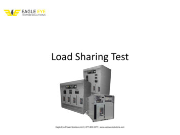
Approach - Integrated OBC using WBGdevices significantly reduces cost,weight, and volume Develop WBG integrated onboard chargerUtilize traction drive inverters and motors as part of the charger converterProvide galvanic isolationProvide high voltage (H.V.) to 14V battery dc-dc conversionUse soft switching for electromagnetic interference (EMI) reduction andefficiency improvement– Develop a control strategy to reduce the bulky dc link capacitor, needed tofilter out the large voltage ripple of twice the fundamental frequency–––– Aggressive pursuit of power density and specific power withoutsacrificing efficiency– All WBG converter (SiC and GaN)– Advanced soft magnetic materials (Nano-composite)120Vor240V6Traction drivemotors &SiC ceptual diagram of anintegrated onboard charger
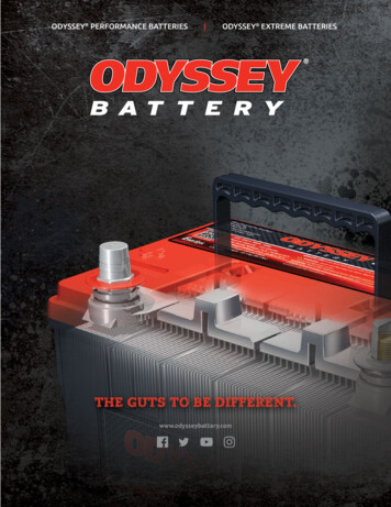
Approach - Integrated OBC (1)HV Traction drive/Front solationconverter14VConverterHV HVbattery14VbatteryHB2DriveShaftMG1MG2NMG1NMG2HV ICEC2CacfCS2To 120 V or 240 VPower Source/LoadHV - Using the three phase inverters as the OBC front converter with the motor zerosequence impedance network (ZSIN) as ac filter inductor Sharing the converter (HB2) and transformer with the 14V battery charger7
Approach - Integrated OBC (1)- Equivalent Circuit for Charging the HV Battery– Three phase inverters as a single phase converter with interleaved switching– Motor zero sequence impedance network (ZSIN) as ac filter inductor8
Approach - Integrated OBC (2) Integrated OBC for traction drive systems with a boost converterTraction drive/Front converterINV/CONVBoost CONVHV HV -HB1TrC1CS114VConverterHVbattery14VbatteryHB2MGHV NMGC2CacfCS2To 120 V or 240 VPower Source/Load9IsolationconverterHV -
Approach - Integrated OBC (3) Other configurations– Integration with the segmented inverter traction drive– Integration with multiphase boost converter The isolation converter can also be applied to standaloneOBCsApproach is flexible and applicable to various tractiondrive system architectures10
Technical Accomplishments and Progress Tested a 5kW Si-based integrated dcdc converter & charger using anisolation converter candidate– Demonstrated the architecture5 kW Si-basedisolation converter(6”x7”x3.5”)Source voltage:200V/divSource current: 50A/divCharging voltage: 500V/divCharging current: 10A/divCharging at 3 kW from a 120V sourceSource voltage:500V/divSource current: 50A/divMeasured efficiencyof the Si-based 5kWchargerCharging voltage: 500V/divCharging current: 10A/divCharging at 5 kW from a 240V source11
Technical Accomplishments and Progress Designed 6.6 kW SiC isolation converter that will be used for buildinga 6.6 kW SiC-Based Integrated OBC– Built-in 14V converter of 2 kW– ORNL designed DBC and SiC switchphase-leg module using Cree SiC MOSFETs– Planar transformer– Heavy copper PCBs– Max. efficiency 98%6.6 kW SiC isolation converter design( 7”x5”x2.7”, 1.55 L)Rds(on) 17mΩ12SiC MOSFET phase-leg modulesstatic characteristicsDBC design for SiCMOSFET phase-legmodules (36x46mm)SiC MOSFET phase-leg modules(36x46mm): 1200V/100A
Technical Accomplishments and Progress Completed primary PCB winding design and14V PCB winding design for a 6.6 kW SiCisolation converter that will be used to builda 6.6. kW SiC on-board-charger– Heavy copper PCBs transformer windings– Two primary PCBs for high voltage windings– Double side copper traces in parallel in 14V PCBwinding for high current Off-the-shelf ferrite planar cores wereresized for use in the 6.6 kW SiC isolationconverter prototype Working with Aegis Technology, generateda transformer core design using their lightweight, low loss nano-magnetic material;sample cores will be produced at the end oftheir SBIR projectCore pieces cut with a diamondsaw (width: 64mm, height: 10mm)13Primary PCB winding design for6.6 kW SiC isolation converter14V PCB winding design for6.6 kW SiC isolation converter
Technical Accomplishments and Progress Developed a SiC MOSFET gate drivercircuit that uses a pulse transformer tosubstantially simplify the gate drive circuit– Sharing gate drive power supplies– Pulse transformers can be built onto the mainPCB boards15 18VBuff VgDSP Circuit simulation results confirmed thepulse transformer based gate drive circuitcan generate adequate gate voltage andcurrent to the SiC MOSFET and producesatisfactory switching behaviors Completed a DSP control board designDSP control board14Pulse transformerbased gate driver boardPulseTr.RCVgs-5VP. Tr. Gate DriverSiCSiCSiC MOSFET gate driver circuitusing a pulse transformerSimulation results
Technical Accomplishments and Progress Performed characterizationtests on GaN switches– Tested EPC eGaN switches( 200V) for use in the 14Vdc-dc converter– Tested IR/Delphi GaN smalland medium size switches(600V) for use in the OBCconvertersEPC eGaN test setup10ns/divDrain source voltage: 20V/divTurn-offTurn-on29ns500ns/div1510ns/divEPC eGaN switching waveforms22ns
Technical Accomplishments and Progress Tested and characterized IR/Delphi 600Vsmall-size GaN switches– Double pulse– Half-bridge converterSiGaNRgIR GaNswitchIR 600V GaNswitch & testboardCH3: vGSB, 10V/div; CH4: iSB, 10A/div;CH6: vDSB, 200V/div; 2us/divTurn-on: 17.35 µJTurn-off: 91.6 µJCH3: vout, 200V/div; CH4: iSB, 25A/div;CH5: vGSB, 20V/div; CH6: vDSB,200V/div; CH7: iout, 25A/div; 2us/div16Math1: 1000*(vds*is), uJ
Technical Accomplishments and Progress Completed a test board design for new IR 600 V medium-size GaNswitches packaged by Delphi– The design is reconfigurable for conducting various tests of doubleSipulse and half bridge dc-dc converter– Heavy copper PCBs– Switches have different embedded gate resistance values– Will choose an optimal gate resistance value for 6.6 kW OBC designGaNRgIR/Delphi 600 V small-size GaNswitch (10x12mm)New test board design17New IR/Delphi 600 V mediumsize GaN switch(17x31mm)
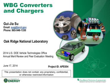
Technical Accomplishments and Progress Performed static characterization tests of IR/Delphi 600 V mediumsize GaN switches 35% lower specific on resistance than the best Si MOSFET (CoolMOS)IR/Delphi 600 V medium-size GaN FETPackage Size: 1.7cmx3.1cmRdson 17mΩSpecific on resistance: 89.6mΩcm2Infineon CoolMOSIPW60R041C6*Typical I-V curve for IR/Delphi600 V medium-size GaN switchPackage Size: 2.1cmx1.6cmRdson 41mΩSpecific on resistance: pe db3a304426e7f13b0127f2050dcb45ac18
Responses to Previous YearReviewers’ CommentsOverall, the reviewers’ comments were very positive. One reviewer commented: “Bidirectional charger capability is also good, but roaming gridinverters face grid integration standard and regulatory changes which are being address by theSmart Grid Interoperability Panel (SGIP) Distributed Renewables, Generation & Storage (DRGS)and the Vehicle to Grid (V2G) Domain Expert Working Groups (DEWGS). The reviewer noted thatORNL and NREL are becoming members of SGIP so it might be appropriate for this project tomonitor these efforts or to coordinate through National Institute of Standards and Technology(NIST).”Response/Action: We agree and will monitor developments in standards and regulations. One reviewer commented: “A cost rational of how this lowers cost was needed.”Response/Action: Passive components contribute more than 30% of the cost of on-boardchargers (OBC). Their size and cost can be significantly reduced by using wide bandgap (WBG)semiconductors and advanced soft magnetic materials to operate chargers at higher frequencies( 300kHz) and with lower losses. In addition, this project is developing integrated chargerconverter topologies that eliminate an additional converter entirely. As the cost of WBG devices(in particular, GaN on Si substrates) drops as technology matures, we believe our approach willlead to low cost, high efficiency, high power density all WBG dc-dc converters and on-boardchargers.19
Partners/Collaborators20 International Rectifier GaN devices (engineeringsamples) and modules, requirements for gate drivers Delphi Packaged GaN power modules Aegis Technology Inc. light-weight, low loss nanomagnetic materials Hitachi/Metglas input on design and fabricationof high frequency inductors and transformers usingFINEMET Ferroxcube USA input on design and fabricationof high frequency inductors and transformers usingsoft ferrites
Proposed Future Work Remainder of FY14– Complete fabrication and test of a 6.6 kW SiC isolation converter prototype– Complete characterization tests of GaN switches– Design a 3.3 kW GaN isolation converter FY15– Assemble and test a 6.6 kW OBC using the 6.6 kW SiC isolation converterbuilt in FY14 and a SiC traction drive inverter– Build and test a 3.3 kW GaN isolation converter– Introduce GaN into the 14V dc-dc stage and design a 6.6 kW all-GaNisolation converter FY16– Build and test a 6.6 kW all GaN isolation converter– Integrate the 6.6 kW all-GaN isolation converter with a WBG traction drivefor an all WBG OBC and test and characterize the integrated OBC21
Summary Relevance: This project is targeted toward leapfrogging the present Si based chargertechnology to address charger and converter cost, weight, volume and efficiencytargets. Approach: The approach being pursued is to overcome the limitations of presentsemiconductor and magnetic materials with WBG devices and advanced magneticmaterials to significantly increase power density, specific power and efficiency at lowercost, and to further reduce cost by using novel integrated topologies and controlstrategies. Collaborations: Collaboration with several industry stakeholders are being used tomaximize the impact of this work. Technical Accomplishments:– Identified one isolation converter candidate and completed test of a 5kW Si-basedintegrated dc-dc & charger using the candidate.– Completed a 6.6 kW SiC isolation converter design using the in-house developedSiC switch phase-leg modules rated at 100A/1200V.– Completed fabrication of several parts for a 6.6kW SiC isolation converterprototype– Conducted tests of EPC eGaN switches for possible use in the 14V dc-dcconverter and IR/Delphi 600 V GaN switches for charger converter designs. Future Work: Build and test 6.6 KW WBG integrated chargers; charger technicaltargets are being developed by DOE in collaboration with industry.22
Performed static characterization tests of IR/Delphi 600 V medium - size GaN switches 35% lower specific on resistance than the best Si MOSFET (CoolMOS) Typical I-V curve for IR /Delphi 600 V medium-size GaN switch . IR/Delphi 600 V medium-size GaN FET . Package Size: 1.7cmx3.1cm R. dson 17. mΩ. Specific on resistance: 89.6. mcmΩ. 2 .