Transcription
January 9, 2018Mr. Leo CosentiniCalifornia State Water Resources Control BoardDivision of Water QualityPO Box 100Sacramento, CA 95812Re:Storm Clean Filtration Systems Application for Trash Treatment Control DeviceCertificationDear Mr. Cosentini,CleanWay Environmental Partners, Inc. is pleased to present this application to the CaliforniaState Water Resources Control Board for the Storm Clean filtration system’s use as a TrashTreatment Control Device. This application contains the complete supporting detail of thesystem according to the Trash Treatment Control Device Application Requirements. Thisincludes the following seven sections:1.2.3.4.5.6.7.Cover LetterTable of ContentsPhysical DescriptionInstallation InformationOperation and Maintenance InformationReliability InformationField/Lab Testing Information and AnalysisThank you for considering this application. Please do not hesitate to contact us if additionalinformation is required.Sincerely yours,CleanWay Environmental Partners, Inc.Steve McInnisOwnercc: Bridget Garlinghouse, CleanWay , Technical Sales EngineerCleanWay Environmental Partners Inc. 800.723.1373 cleanwayusa.com PO Box 30087 Portland OR 97294
1.01.A.COVER LETTERGeneral description of the Device.The Storm Clean Filtration System is a full capture drop inlet filtration insert comprised of threecomponents: a pan, a strainer, and an optional fabric or media filter. The steel strainer has 3/16”(4.8 mm) openings and effectively captures particles 5mm or greater.1.B.The applicant’s contact information and location.CleanWay has been manufacturing the stormwater filtration systems in Portland, Oregon sincethe late 1980s. We can be reached 8am to 5pm Monday through Friday at 800-723-1373.CleanWay’s California Full Capture device contact:Bridget Garlinghouse, EITTechnical Sales EngineerCleanWay Environmental Partners, Inc.PO Box 30087Portland, OR com1.C.The Devices’ manufacturing location.Fabrication of all units occurs at the physical location listed below:CleanWay Environmental Partners, Inc.5410 NE 109th AvePortland, OR 972201.D.A brief summary of any field/lab testing results that demonstrates the Devicefunctions as described within the application.The Storm Clean Filtration System directs all water and particles or trash carried with the waterthrough a screen with 5mm openings. No particles equal to or greater than 5mm diameter canphysically escape the system unless the system is in bypass. In addition to the set physical sizelimitations of the screen, trash collection performance testing is currently being conducted forfurther characterization of the system. This information is available upon request and will beadded as an amendment to the application once finalized.1.E.A brief summary of the Device limitations, and operational, sizing, andmaintenance consideration.The Storm Clean Filtration system is easy to install and maintain, requiring no special tools.These systems are offered in standard sizes and custom designs for varying sizes and inletstyles. The device is limited to a minimum depth of 12” and grated inlet size of 16”. Maintenanceand operation of the unit should be performed on a monthly basis to ensure the device is1
Application for Storm Clean FilterFull Capture System Certification to theCalifornia State Water Resource Control BoardCleanWay Environmental Partners, Inc.PO Box 30087Portland, OR 972943
2.0TABLE OF CONTENTS3. PHYSICAL DESCRIPTION .Subsection 3.A .Subsection 3.B .Subsection 3.C .Subsection 3.D .Subsection 3.E .Subsection 3.F .Subsection 3.G .Subsection 3.H .Subsection 3.I . .Subsection 3.J .6667788899124. INSTALLATION INFORMATION Subsection 4.A .Subsection 4.B .1313135. OPERATION AND MAINTENANCE INFORMATION .Subsection 5.A .Subsection 5.B .Subsection 5.C .Subsection 5.D .14141414156. RELIABILITY INFORMATION .Subsection 6.A .Subsection 6.B .Subsection 6.C .161616167. FIELD/LAB TESTING INFORMATION AND ANALYSIS 164
List of TablesTable 1. Alternative configurations for Storm Clean filtration inserts .Table 2. Storm Clean standard design filtration specifications.Table 3. Storm Clean product materials 678List of FiguresFigure 1. Cleaned drop inlet for Storm Clean filtration insert.Figure 2. Installation of Storm Clean drop inlet insert with media filter.Figure 3. Installation of Storm Clean drop inlet insert with fabric filter. . Figure 4. Installed square Storm Clean drop inlet insert . . Figure 5. Installed round Storm Clean drop inlet insert Figure 6. Installed rectangular Storm Clean drop inlet insert. Figure 7. Storm Clean sample port and vector control point of access . APPENDICIESAppendix A.Standard Drawings for Storm Clean filtration unitsAppendix B.Client worksheet: Measure your Catch BasinAppendix C.Inspection and Maintenance ChecklistAppendix D.CleanWay Limited Product Warranty59101011111214
3.03.A.PHYSICAL DESCRIPTIONDesign drawings for all standard Devices sizes including dimensions, andalternative configurations.Design drawings for Storm Clean filtration system devices are included in Appendix A.Alternative configurations for the Storm Clean filtration inserts are described in Table 1, below.Table 1. Alternative configurations for Storm Clean filtration insertsItem No.DescriptionAlternativeRT x SED-llStorm clean-ll complete filter insert for rectangularcatch basin with standard non-woven fabricsediment element. Specified dimensions.For non-standard rectangularbasins sized 20” and upRT x SED-lllStorm clean-lll complete filter insert for rectangularcatch basin with standard non-woven fabricsediment element. Specified dimensions.For non-standard rectangularbasins sized 16” and upRD x SED-llRound type ll complete with non-woven fabricsediment element with special dimensionsFor non-standard round basinssized 20” and upRD x SED-lllRound type lll complete with non-woven fabricsediment element with special dimensionsFor non-standard round basinssized 16” and upSQDS x SED-llSquare dual strainer w / non-standard dimensionincludes adsorb-it fabric elementsFor square basins sized 35” andup, accommodates larger flowsRTDS x SED-llRectangular filter insert with dual strainers and nonwoven geotextile elements. Specified dimensions.For rectangular basins sized 35”and up, accommodates largerflowsStorm clean-ll repl strainer, 16” depth, 0.97 ftcapture capacity3RPSTRN-llFor shallow basins,accommodates depth limitationsStorm clean-ll repl strainer, 12” depth, 0.73 ftcapture capacity3RPSTRN-llFor shallow basins,accommodates depth limitations3.B.Description on how the Device works to trap all particles that are 5mm or greaterin size and how it is sized for varying flow volumes.Storm Clean drop inlet filtration systems include two components: a pan, a strainer. Anoptional third component can be added for water quality improvement such as a fabric or mediafilter. The modular pan is designed to conform to the existing basin specifications. It ispositioned across the inlet of the storm drain, resting on flanges that set on the basin grateframe, below the grate. The pan’s three main features are the sample port, the overflow bypassorifice, and a tapered collar for strainer and optional filter placement. The strainer, a truncatedcone design, is constructed with 3/16” (4.8 mm) perforated steel sheet on 1/4” (6.35 mm)centers. It drops below the pan to sit inside the basin, and includes a bail handle for ease ofinstallation and servicing. The filter component, an optional addition for improved water quality,surrounds the strainer completely, and is suspended below the pan. The following filter optionsare available: non-woven geotextile fabric for sediment and TSS removal, ADsorb-It lipophilic6
filtration fabric for oil and hydrocarbon removal, MetalZorb dissolved heavy metals removalmedia, and other specialty media for site specific needs.The filtration system is designed for use in both existing and new storm drain infrastructure.Standard insert sizes fit both square two foot by two foot, and round two foot diameter gratedinlets. Since the design is modular, non-standard size variations are available at comparablecost. The modular and scalable portion of the insert is the pan, which houses the strainer andoptional filter. Strainers and filters are offered in a range of sizes to accommodate the basin andtreatment needs. The standard strainer length is 22 inches. To ensure 100% capture ofpollutants and trash, the pan is fitted with hatch style gaskets around the flanged ends. Thisdesign forms a seal between the basin frame, grate, and insert.Sizing variations are available for inserts based on the storm drain specifications. Includedvariations are dual strainer inserts and various strainer depths, as shown in Table 1 on theprevious page.3.C.The Device maximum trash capture capacity.See subsection 3.D. for maximum trash capture capacity for standard Storm Clean filtrationsystems.3.D.The Device hydraulic capacity (flow in cfs) at its maximum trash capture capacityfor all standard Device sizes.Table 2, below, provides the standard design filtration specifications for typical Storm Clean drop inlet filtration units including capture capacity and hydraulic capacity.Table 2. Storm Clean standard design filtration specificationsItem No.DescriptionCapture3Capacity (ft )Hydraulic Capacity(cfs)SQ24SED-llStorm Clean-ll insert complete w/ non-wovensediment element for square 24” drop inlet1.33Nominal: 0.089Max: 0.18RD24SED-llStorm clean-ll complete filter insert for round 24”drop inlet with standard non-woven fabric sedimentelement.1.33Nominal: 0.089Max: 0.18RT x SED-llStorm clean-ll complete filter insert for rectangularcatch basin with standard non-woven fabricsediment element. Specified dimensions.1.33Nominal: 0.089Max: 0.18RD x SED-llStorm clean-ll complete filter insert for round dropinlet with standard non-woven fabric sedimentelement. Specified dimensions.1.33Nominal: 0.089Max: 0.18*NOTE: The trash capture capacity will remain constant with or without the optional filterelement.7
3.E.Conditions under which the Device re-introduces previously trapped trash.Trash reintroduction will occur in unit when strainer basket is completely filled and floatabletrash exits through the overflow bypass orifice. The standard overflow orifice is one inch tall byeight inches wide, and is custom designed accordingly for outgoing pipe capacity.3.F.Each material and material grade used to construct the Device (stainless steel,plastic, etc.).See subsection 3.G. for material and material grade of the components of the Storm Clean filtration insert.3.G.Estimated design life of the Device.Table 3, below, details the materials and material grades used in Storm Clean drop inletfiltration products. The design life of hardware components and filters is dependent onhousekeeping, maintenance, and frequency of catch basin service. The listed design life is ratedfor average filter loading, average service frequency, and consistent housekeeping (i.e.sweeping).Table 3. Storm Clean product materialsItem No.RPPAN-llDescriptionStorm Clean-ll insert panwith gasketMaterial(s)Material GradeStainless Steel orPowder Coated MildSteel#16 304#2B Stainless#14 ASTM A36 MildSteelHatch style gasket, 3/8”bulbDesign Life10 years3-5 yearsRPSTRN-llStorm clean-ll strainerStainless Steel orPowder Coated MildSteel# 20 304#2B Stainless#20 ASTM A36 MildSteel10 yearsFPSED-llNon-woven geotextilesediment fabric filterelementTerraTex N08nonwoven geotextileASTM D44911-3 monthsADsorb-it filtrationfabricASTM D44911-3 monthsASTM C516-083-6 monthsADsorb-it oil andFPSEDHC-ll hydrocarbon fabric filterelementFPVSAD-llStorm Clean-ll absorptionVermiculite adsorbentfilter element withmediavermiculiteMPFS-M-llMedia pack for type-llStorm clean with 75%MetalZorb type M andvermiculite blendMetalZorb andvermiculite sorbentmediasBiodegradable toASTM D68686-12 monthsRP4.58ABSSample port plug 4 5/8"ABS disc cover New styleABS plastic andPolyethylene foamASTM D4673-023-5 years8
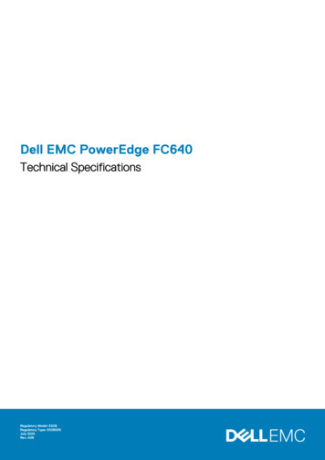
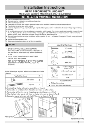
3.H.Engineering plans/diagrams for a typical installation.Engineering plans/diagrams for a typical installation of the Storm Clean filtration insert areprovided in Appendix A along with the standard dimensions.3.I.Photographs, if any, of pre- and post-installation examples.Figures 1 through 6 illustrate the installation process of a Storm Clean filtration insert, beforeand after complete installation. Inserts fit all sizes including but not limited to square, round, andrectangular basins.Figure 1. Cleaned drop inlet for Storm Clean filtration insert9
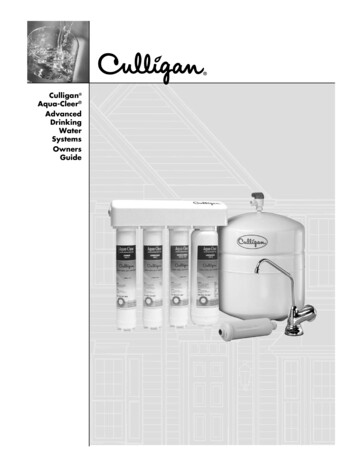
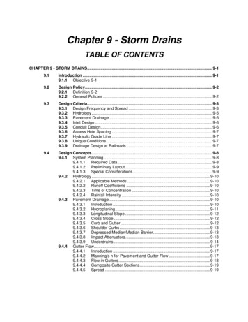
Figure 2. Installation of Storm Clean drop inlet insert with media filterFigure 3. Installation of Storm Clean drop inlet insert with fabric filter10
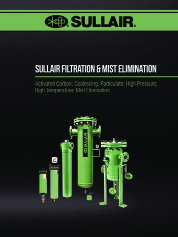
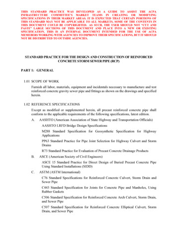
Figure 4. Installed square Storm Clean drop inlet insertFigure 5. Installed round Storm Clean drop inlet insert11
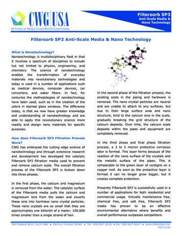
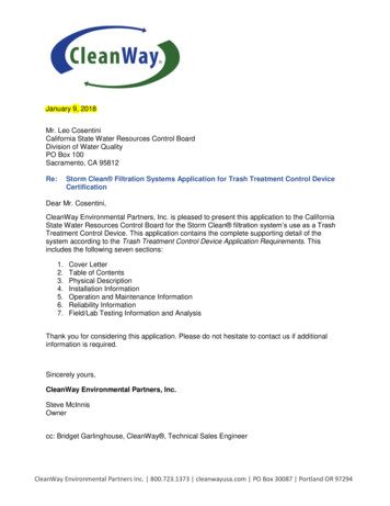
Figure 6. Installed rectangular Storm Clean drop inlet insert3.J.If the device is designed with an internal bypass, explain how the bypass onlyoperates with flows greater than the design storm.During rainfall events that receive flows that are greater than the design storm of a one-year,one-hour storm in the subdrainage area bypass of the filter can be activated. The bypass of thefiltration unit occurs when flows exceed 0.18 cfs. Bypass is when water flows through theoverflow orifice which is a one inch by eight inch slot located above the level of the strainer. Anyfloatable trash that is can fit through the orifice opening will bypass the strainer and will not becaptured.12
4.04.A.INSTALLATION INFORMATIONDevice installation procedures and considerations.The specifications detailed in the client worksheet, provided in Appendix B, are used to designyour Storm Clean drop inlet insert. Installation procedures are described in the steps below.This information is also provided upon purchase and the delivery of a Storm Clean insert.1. Remove grate and thoroughly clean drop inlet basin, grate, and grate support frame. Werecommend the host fixture is pressure washed using a vacuum or combination truck.2. Inspect drop inlet, grate, and frame to ensure the basin is operational. The grate frameshould be solid and clean prior to install filtration insert. Any holes or broken sections of theframe will affect the 100% capture seal between the rubber hatch gaskets and frame.3. MEDIA FILTERS ONLY: Uncouple the snap ring from inside vinyl upper sleeve of the mediafilter element.4. MEDIA FILTERS ONLY: Support the collection pan about 3 feet off ground in a horizontalposition.5. MEDIA FILTERS ONLY: Place the filter element under the collection pan. Bring vinyl uppersleeve, with the coupling ring, of the media filter up through tapered collar. Start at an openend of snap ring and work the ring around until the ends of the ring can be reconnected.6. Install the collection pan into the basin. Make sure the rubber gasket on the collection panhas good contact with the grate frame.7.FABRIC FILTERS ONLY: Install the fabric filter element until it fits snugly into the supportpan opening.8.Install rigid strainer into the filter element until the strainer is flush with the support pan. Thiswill be a snug fit. If the strainer does not sit flush, check for obstructions and proper filterinstallation.9. Ensure the sample port cap is firmly in place, then reinstall grate.4.B.Methods for diagnosing and correcting installation errors.The filtration unit’s modular design reduces installation errors since it is fabricated with thebasins specific specification. The two bullets below are diagnoses for common errors.A. If grate does fit inside basin: check grate frame connection to determine if insert is properlyinstalled on grate frame. If grate will not connect to frame, contact the customer support line at800-723-1373.B. If strainer doesn’t sit flush with pan: check filter installation, and check for obstructions belowthe strainer. If obstructions are present, rotate the pan until strainer sits flush. Contact thecustomer service team at 800-723-1373 if you are unable to solve this issue.13
5.05.A.OPERATION AND MAINTENANCE INFORMATIONDevice inspection procedures and inspection frequency considerations.Visual monitoring of the filtration unit to check performance should occur on a monthly basis,during routine inspection. During the wet season, October through April, the unit should beinspected after a heavy rainfall event. Inspection of loading can be performed through the grateto determine whether cleaning is required. To inspect unit performance and status, a tool to liftgrate is necessary (i.e. a grate hook). Observe the capture capacity of the unit’s strainer todetermine if cleaning is required. Check all hardware components to ensure unit is structuralsound with the “Inspection-Maintenance Checklist” provided in Appendix C.5.B.Maintenance procedures, including a description of necessary equipment andmaterials.Servicing the Storm Clean drop inlet insert requires a grate hook to access the unit. Werecommend using a vacuum or combination truck to accomplish maintenance for safety ofoperator and 100% containment of pollutants and trash. Utilize the “Inspection-MaintenanceChecklist” provided in Appendix C while servicing the unit to ensure all aspects structuralaspects of components have been maintained.1. Remove grate to access the unit for cleaning.2. Remove and empty the rigid strainer.* This should occur when the strainer is at 75% orgreater capacity to avoid overflow of floatable trash through bypass orifice.3. Remove filter element.* Filter elements should be changed when the unit is heavily fouled atthe surface and sedimentation has built up, impeding the flow of water.The used filter element should be allowed to drain, and be disposed as solid waste*.4. Replace filter element with a new one, following the installation instructions.*Check with your local waste disposal authority for proper disposal of exhausted filterelements and waste materials removed from the system.Maintenance is easy with your CleanWay filter; watch a service technician preform maintenanceat the following YouTube link: https://youtu.be/3L980PJUyHQ.5.C.Maintenance frequency considerations, including effects of delay.Maintenance of the unit should occur at 75% capture capacity. The frequency of this should bedetermined during routine monthly inspections of the unit. High Priority Land Use areas with ahistory of frequent basin cleaning and litter clean-up will potentially require weekly servicing.This will depend on whether other BMPs are in place, such as sweeping, litter control, etc.Delayed servicing and maintenance of the unit will re-introduce trash and debris into the MS4system.14
5.D.Device maintenance and vector control accessibility.The Storm Clean filtration insert provides easy vector control through the sample port opening,with access to the sump of the drop inlet. Figure 7 displays where vector control maintenancecan be performed. If the optional filtration component is included in the Storm Clean system, thevector abatement product can be placed inside the filter element, below the strainer, for periodicrelease of insecticide.Figure 7. Storm Clean sample port and vector control point of access15
6.06.A.RELIABILITY INFORMATIONDevice sensitivity to loadings other than trash (i.e., leaves, sediment).CleanWay Environmental Partners has been field testing storm drain filtration units for over 20years. The company was started in 1995 in the Pacific Northwest, and has worked alongsideenvironmental service providers to ensure offered products are effective in achieving removalgoals and easily managed by the end user. The smooth design of the strainer will preventsnagging and catching of leaves and other fibrous debris that has a tendency to stick to roughsurfaces. Sediment will not cause any issues with the removal effectiveness, as any particlelarger than 5mm will entrap inside the strainer. If a filter element is added to the unit, sedimentwill accumulate over time, and the filter will need to be replaced. Filter elements contain anadditional 3” sump below the strainer to capture fines that pass through the 3/16” (4.72 mm)strainer. Replacement schedules depend on the site conditions where the unit is installed. Thegeneral recommended replacement frequency can be referenced in Table 3 of subsection 3.Gon page 8.6.B.Warranty information.Warranty information is provided in Appendix D. Upon receiving the Storm Clean filtrationinsert, inspect all components for quality. Notify your sales associate or our customer serviceteam if any defects are discovered during inspection. Do not install any portion of the insert.CleanWay does not accept returns on any used filter elements under the manufacturer’swarranty.6.C.Applicants customer support.Customer support is available 8am – 5pm PT at 800-723-1373 or support@cleanwayusa.com.Feel free to call one of our representatives to answer any questions or concerns.7.0FIELD/LAB TESTING INFORMATION AND ANALYSISProvide any available field or lab testing information that demonstrates the Devicefunctionality. If device does not include a 5 mm screen within its design, the applicantmust provide adequate testing that demonstrates it traps trash particles of 5 mms ormore.The Storm Clean Filtration System directs all water and particles or trash carried with thewater through a screen with 5mm openings. No particles equal to or greater than 5mmdiameter can physically escape the system unless the system is in bypass. In addition to the setphysical size limitations of the screen, trash collection performance testing is currently beingconducted for further characterization of the system. This information is available upon requestand will be added as an amendment to the application once finalized.16
APPENDIX A:Standard Drawings for Storm Clean filtration units17
APPENDIX B:Client Worksheets18
MEASURE YOUR CATCH BASINDate: Email:Contact: Phone:Company:Site Address:Catch Basin Part Number (if applicable)Note anyadditionalfeaturesCatch Basin / GrateABCDEMeasurementCatch Basin / GrateGrate outer diameterSump depthGrate frame inside diameterFGrate frame heightGKTop of outlet to surface gradeReinforced grate thickness (center)Clearance to outlet pipe/baffleLReinforced grate thickness (edge)Grate frame widthMFlat grate thicknessMeasurementPlease send any photos of your catch basin and grate to assist with accurate sizing.DPlan ViewElevation ViewCheck one:reinforcedor flat 2016 CleanWay Environmental Partners, Inc. All rights reserved. 800.723.1373 info@cleanwayusa.com cleanwayusa.com
MEASURE YOUR CATCH BASINDate: Email:Contact: Phone:Company:Site Address:Catch Basin Part Number (if applicable)Note anyadditionalfeaturesCatch Basin / GrateABCDEFMeasurementCatch Basin / GrateGrate width (outside)Grate length (outside)Grate width (inside)GHJTop of outlet to surface gradeGrate frame heightGrate frame widthGrate length (inside frame)KReinforced grate thickness (center)Sump depthLReinforced grate thickness (edge)Clearance to outlet pipe/baffleMFlat grate thicknessMeasurementPlease send any photos of your catch basin and grate to assist with accurate sizing.Plan ViewElevation ViewCheck one 2016 CleanWay Environmental Partners, Inc. All rights reserved. 800.723.1373 info@cleanwayusa.com cleanwayusa.com
This page intentionally left blank
APPENDIX C:Inspection and Maintenance Checklist19
Inspection-Maintenance ChecklistName:Date:Company:Grate Replace Broken MissingNotes:Strainer (Mild Steel / Stainless Steel) Replace Broken MissingNotes:Filter Element Replace Broken MissingType(circle): SED / SEDHC / SAD / MetalZorb blendNotes:Pan (circle): Round / Rectangular / Square Replace BrokenGasket Replace MissingNotes:Sample Port Replace Broken MissingNotes:Catch BasinType(circle): Round / Rectangular / Square Repair BrokenNotes:Site and Catch Basin Location Notes:CleanWay Environmental Partners, Inc. cleanwayusa.com 800.723.1373 info@cleanwayusa.com
APPENDIX D:Product Warranty20
www.cleanwayusa.comCleanWay Limited Product Warranty StatementExtent of Limited WarrantyCleanWay Environmental Partners Inc. (CleanWay) warrants to the end-user customer that CleanWay products willbe free from defects in material and workmanship for a period of one year (12 months).CleanWay does not warrant that the operation of any product will be uninterrupted or error free.CleanWay’s limited warranty covers only those defects that arise as a result of normal use of the product and doesnot cover any other problems, including those that arise as a result of: (i) improper installation, maintenance ormodification; (ii) media, parts or supplies not provided or supported by CleanWay; (iii) operation outside theproduct’s specifications; or (iv) unauthorized modification or misuse.If CleanWay receives, during the applicable warranty period, notice of a defect in any product which is covered byCleanWay’s warranty, CleanWay shall either repair or replace the product, at CleanWay’s option.CleanWay shall have no obligation to repair or replace until the customer returns at their expense the defectiveproduct to CleanWay.The customer shall be responsible for any shipping and handling charges incurred in delivery of products coveredunder warranty.Any replacement product may be either new or like-new, provided that it has functionality at least equal to that ofthe product being replaced.CleanWay replacement products may contain remanufactured parts, components, or materials equivalent to new inperformance.CleanWay’s Limited Warranty Statement is valid in any country where the covered CleanWay product is distributedby CleanWay.Limitations of WarrantyTO THE EXTENT ALLOWED BY LOCAL LAW, NEITHER CLEANWAY NOR ITS THIRD PARTY SUPPLIERSMAKES ANY OTHER WARRANTY OR CONDITION OF ANY KIND, WHETHER EXPRESS OR IMPLIEDWARRANTIES OR CONDITIONS OF MERCHANTABILITY, SATISFACTORY QUALITY, AND FITNESS FOR APARTICULAR PURPOSE.Limitations of LiabilityTo the extent allowed by local law, the remedies provided in this Limited Warranty Statement are the customer’ssole and exclusive remedies.TO THE EXTENT ALLOWED BY LOCAL LAW, EXCEPT FOR THE OBLIGATIONS SPECIFICALLY SET FORTHIN THIS WARRANTY STATEMENT, IN NO EVENT SHALL CLEANWAY OR ITS THIRD PARTY SUPPLIERS BELIABLE FOR DIRECT, INDIRECT, SPECIAL, INCIDENTAL OR CONSEQUENTIAL DAMAGES, WHETHERBASED ON CONTRACT, TORT, OR ANY OTHER LEGAL THEORY AND WHETHER ADVISED OF THEPOSSIBILITY OF SUCH DAMAGES.CleanWay Environmental Partners Inc. PO Box 30087 Portland, OR 97294 800.723.1373 Fax: 503.288.3658
filtration fabric for oil and hydrocarbon removal, MetalZorb dissolved heavy metals removal media, and other specialty media for site specific needs. The filtration system is designed for use in both existing and new storm drain infrastructure. Standard insert sizes fit both square two foot by two foot, and round two foot diameter grated inlets.