Transcription
Alignment of Optical Systems Using Lasers:A Guide for the Uninitiatedby David M. Bentondoi: http://dx.doi.org/10.1117/3.2603804PDF ISBN: 9781510646209Published bySPIE PressP.O. Box 10Bellingham, Washington 98227-0010 USAPhone: 1 360.676.3290Fax: 1 360.647.1445Email: Books@spie.orgWeb: http://spie.orgCopyright 2021 Society of Photo-Optical Instrumentation Engineers (SPIE)All rights reserved. No part of this publication may be reproduced or distributed in anyform or by any means without written permission of the publisher.This SPIE eBook is DRM-free for your convenience. You may install this eBook on anydevice you own, but not post it publicly or transmit it to others. SPIE eBooks are forpersonal use only; for more details, see he content of this book reflects the work and thoughts of the author(s). Every effort hasbeen made to publish reliable and accurate information herein, but the publisher is notresponsible for the validity of the information or for any outcomes resulting from reliancethereon.Spotlight vol. SL61Last updated: 31 August 2021
Table of Contents1 Introduction1.11.21A word about laser safetyLaboratory good practice222 How Alignment Can Go Wrong2.12.22Basic alignmentElemental components and controls3 Working with Lenses3.13.23.33.43.53.65Lens actionFocal spot sizeCollimationDivergence reduction using beam expandersGaussian beamsChromatic aberration4 Defining the Optical Axis4.1346679101111The dog leg: the foundation stone of alignment145 Focusing into a Fiber156 Aligning an Interferometer186.16.2The Michelson interferometerThe Mach Zehnder interferometer18217 Aligning with Lenses238 The Shearing Interferometer for Testing Collimation249 Alignment of Near-Infra-Red Beams2410 The Retroreflector as a Useful Tool2510.1 Fiber to free space and back: an example of the use of a retroreflector11 Concluding Remarks2729iii
SPIE Spotlight SeriesWelcome to the SPIE Spotlight series! This growing collection of concise eBooksserves as an entry point for particular topics in optics and photonics suitable forresearchers, engineers, managers, executives, and educators. Spotlights fill thecommunity need for timely and relevant references at a level of detail bridgingthe gap between in-depth journal articles and broad fundamental tutorials.Whatever your interest or need, we hope this series meets your expectations andencourage you to submit your own ideas for future Spotlights online.Craig Olson, Series EditorL3 TechnologiesAssociate EditorsBrian SorgNational Cancer InstituteBiomedical Optics/Medical ImagingRichard BlaikieUniversity of OtagoSemiconductor, Nano-, and Quantum TechnologyKeith KasunicOptical Systems GroupAerospace and DefenseMatthew JungwirthCyberOptics Corp.Optical Design and EngineeringRonian SiewinopticalsolutionsAerospace and DefenseWei LiStanford UniversityEnergy and the Environment,
PrefaceI learned the basics of optical alignment initially from my PhD supervisor and therest I acquired over 3 decades in optical laboratories. Seemingly little has changedfor this process of knowledge acquisition even though the world of scientific publishing has vastly expanded and moved to an electronic format. There is a lot ofinformation about what to do with optics, seemingly little about how to go aboutdoing it. Hence I decided to record the thoughts and methods I use regarding optical alignment. This book is not intended to be rigorous in scientific detail, more aguide to point you in the right direction. Neither is this book a beginners guide tooptics but assumes familiarity with light, its control and the basic componentsused. You ultimately learn optical alignment by doing it, but you can save a lotof time by starting out in the right direction.v
Benton: Alignment of Optical Systems Using Lasers: A Guide for the Uninitiated11 IntroductionThe alignment of optical systems is a skill. It is a skill that is often overlooked orassumed to be obvious. Maybe this arises from a view of “aligned” optical systems that is easily understood, inherently interpretable. Maybe it arises becauseoptical experiments can be performed at school and are therefore assumed to besimple. But anyone who has spent time in an optics lab will know the frustrationof spending hours, sometimes days, trying to effectively align an optical system,so where does this disparity between perception and reality come from?Perhaps, it is that undergraduate experience of optics experiments. I often explainto students that the difference between education and research is that as a studentyou embark on a known path where the experiment has been constructed; there isa method and an expected result. This is not the case with research where youneed to decide upon an appropriate method, which may not work. There is notnecessarily a defined endpoint. You may spend a considerable time pursuingone line of investigation, to then abandon it and try something different. With predefined experiments, you usually make use of optical rails to mount optical components and these are known to be compatible with each other. This significantlyreduces the difficulties involved with alignment.This Spotlight is aimed at someone new to the optics lab such as a newresearch student but not new to the ideas of optics, i.e., you understand that a lensfocuses light. (It may seem strange to say this but I have met many people whodid not actually know what to do with a lens or how it works.) This Spotlight provides the philosophy and rationale behind optical alignment. Aligning optical systems is a skill that is acquired through several years of constructing opticalsystems of various kinds, yet it is not something we tend to celebrate with lineson our CV. It is a skill that comes through patience and failure. If a student needsto understand an aspect of science, there are countless journal papers and textbooks to refer to. There is very little on learning to do optical alignment.1 A useful source of information is to be found with the optical equipment manufacturerswho often provide tutorials and primers on how to use items of optical equipment.2–4 These are very useful and informative but do not give instruction onhow to perform fundamental alignment procedures.As a research student, you are presented with a clear optical table on whichyou have to produce an aligned system. You may have to choose which elementsand which form of mounts you will need. You will assume that you know how toproceed and then you will find that it takes much longer than you expected, youchange the setup often and then your supervisor will come in and changeeverything.This Spotlight is intended to pass on some nuggets of knowledge about howto go about setting up an optical alignment using a laser and some tricks to useto make life easier. Hence there are other topics that are important to grasp, topicsthat may have been presented in lectures but not faced in reality—such as
2Benton: Alignment of Optical Systems Using Lasers: A Guide for the Uninitiatedchromatic effects and collimation. It is not intended to be rigorously scientific inits approach but more as a companion on your optics journey.1.1 A word about laser safetyYou must make sure that you familiarize yourself with the laser usage and safetyprocedures in your laboratory. Every organization should have its own set of procedures and policies regarding working with lasers and risk management. A quickinternet search will provide you examples and generalist sites, such as Wikipedia,give a good accessible overview1 (see Ref. 5 for a more in-depth appreciation). Itis not necessary to use bright lasers to achieve alignment; we are mostly interestedin a lasers ability to travel in a straight line. I would strongly recommend that lasersare attenuated (using neutral density filters) and should be well below the level of1 mW, ideally 100 μW, making them class 2. (This is ideal, it may not be possibledepending on your laser and system.) Laser safety procedures will assess the nominal ocular hazard distance (NOHD) for the laser you are using. If it is deemed thatyou need to wear personal protective equipment, i.e., protective goggles, this willbe a major hindrance because you will not be able to see the beam you aretrying to use. Thus using a low-power laser with a short NOHD is ideal here.1.2 Laboratory good practiceNever touch the optical surface of an optical element with bare fingers. Sweat andgrease from your fingers will leave marks and can impact upon optical performance. Handle lenses and mirrors by their edges. In other cases, such as beamsplitters, wear disposable gloves.Do not leave unmounted lenses lying on a hard optical table. This can scratchthe middle of the lens surface. Do not leave mirrors face down for the same reason. Return optical elements to their packaging or protective case.Do not mix metric and imperial equipment together. You might be able tomake an imperial thread fit in a metric hole, but you will almost certainly damagethe thread within the hole and you may get components permanently attached. Itis extremely frustrating to pick up a piece of mounting equipment to find it doesnot fit with all the other equipment you have put together.Before embarking upon aligning a system, draw a schematic diagram of thesystem showing all the components you will need, their relative positions, andwhat their functions will be.White business cards make excellent screens for viewing the beam at variouspoints in the chain of optical elements.2 How Alignment Can Go WrongLet us start with an example task. Your job is to take a laser, focus it though apinhole then expand the beam and direct it with a mirror to a camera. It does
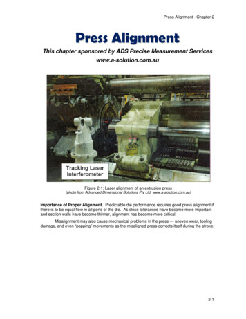
Benton: Alignment of Optical Systems Using Lasers: A Guide for the Uninitiated5Figure 3 The basic adjustments found on typical mounts for optical elements. (a) Lateraladjustments for a lens, (b) angular adjustments for a mirror, (c) angular adjustment on amounting table, and (d) lateral focus adjustment for a lens.table upon which cube beamsplitters or prism is mounted, although in this caseFig. 3(c), rotation of the post in its holder is an important adjustment. The finaladjustment is lateral displacement of a lens along the z direction to change focalposition [Fig. 3(d)] in this case achieved by threaded tube mounts. There are otherways to achieve this such as placing the entire mount on a translating table,usually adjusted with a vernier drive. Often a lens in such a mounting will alsoneed to be mounted with type (a) giving three adjustment directions.3 Working with LensesBefore getting stuck-in to the process of alignment, it is important to get a graspof what optical components are actually doing. The fundamentals of opticaltheory are widely accessible in many textbooks and websites.2,7–9 Here, I willrelate only those things that are needed for a fundamental grasp of using lenses.The focusing properties of lenses are most familiar in the form of the thin lensequation:711 1¼ þ ,fu v(1)where u is the distance from the object to the lens, v is the distance from the lensto the image, and f is the focal length of the lens. We are assuming here that thisis a single lens that is “thin.” (Multielement lenses, such as one on a camera,
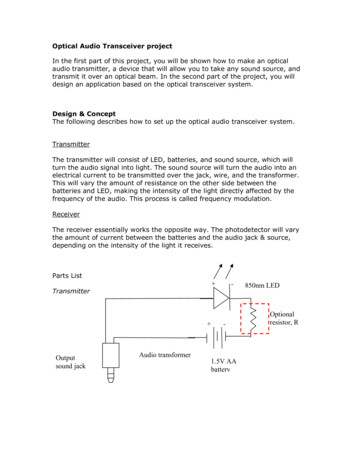
Benton: Alignment of Optical Systems Using Lasers: A Guide for the Uninitiated113.6 Chromatic aberrationThe refractive index of a material is the ratio of the speed of light in vacuum tothe speed in that material. It is this difference in speed that causes light to refractas it transitions into and out of the material. The refractive index is dependentupon the frequency. In the case of glass, water and other light transparent materials the refractive index increases with frequency, or as the wavelength decreases.Thus blue light experiences a higher refractive index than red light. We knowfrom the well-known Snell’s law that higher refractive indices result in largerangles of refraction, thus blue light entering the curved surface of a lens isrefracted more than red light. The result of this is that blue light is focused closerto the lens than red light, which in imaging terms is an effect called chromaticaberration. The effects of chromatic aberration can be systematically reduced bycombining two lenses (a positive and a negative lens which show opposite chromatic effects) made of materials of differing refractive index into a single combined lens known as a doublet lens. This will usually seek to focus the red andblue wavelength to near the same point with the green portion being separated alittle. The difference between a singlet and doublet lens is shown in Fig. 8. Notethat chromatic aberration is not removed, just reduced.A little thought may prompt the question “Why do I need to worry aboutchromatic aberration if I am using a laser which is a single wavelength?” Well,if you are only using the laser then that is fair enough. But if you are using thelaser to align a system that will be used with broadband light then chromatic aberration will be an issue. If you plan to use different lasers with different colorschromatic effects will be present. Chromatic aberration is mentioned in order thatyou can plan ahead based on the use of your optical system. If you know that youare going to be using multiple wavelengths then expect chromatic aberration anduse doublet lenses accordingly, it will reduce problems in the long run. Also doublet lenses are often designed to reduce other aberrations such as coma andspherical aberration that can be present in singlet lenses, thus they can improveimage quality, reducing focal spot sizes.Imaging systems, such as cameras, are broadband and must account for chromatic aberrations to produce good quality images. They use compound lens systems to correct chromatic and other aberrations. Therefore, it can often behelpful to use a camera lens if you are wanting to produce an image or even justa good quality consistent focal position. Often small (C-mount) camera lenses canbe obtained cheaply or second-hand film camera lenses can be useful—it ismounting them that will be the biggest problem!4 Defining the Optical AxisThe laser is your friend when it comes to alignment. We all know that laserstravel in straight lines—so in the initial example alignment case we can use thelaser to define where the elements should go, not the other way around. In a
12Benton: Alignment of Optical Systems Using Lasers: A Guide for the UninitiatedFigure 8 Different focal planes of red and blue light with a representation of focal spot sizefor red and blue at the respective focus. (a) A singlet lens and (b) a doublet lens withreduced aberration.system like the poor example shown initially, all the problems arise from the laserpointing up slightly. So let us set out a procedure to align that system correctly. The first thing that should be done is to ensure that the laser travels in ahorizontal plane. Once we have done this, we can “see” where the opticalaxis is. The preferred way to do this is using two adjustable apertures.We choose a height for the laser, then set the height of the apertures tobe the same as the laser by placing them right next to the laser, seeingthe laser pass through, and reducing the aperture size, progressively tweaking the height.Now separate the two apertures by say, 0.5 m or more and see if the laserpasses through both apertures. Adjust the tilt of the laser—usually theheight of the rear of the laser support. (You defined the front height to bethe same as the apertures so do not change that!) Also twist the laser as
Benton: Alignment of Optical Systems Using Lasers: A Guide for the Uninitiated 15Mirror M2 should be lined up as close as possible to be in line with theoptic axis through apertures A1 and A2.Set the height of the center of M2 to match the aperture height. Now placeM1 to direct a beam from the laser onto M2—this is where the change inheight between laser and system is rectified.Next steer the beam using M2 to pass through the aperture A1. If you havedone a good alignment by eye, the beam should appear somewhere nearthe aperture A2 (as shown in Fig. 9).At this point, your instinct will be to try and steer the beam through thesecond aperture and as you do this you will find the beam disappears asit does not pass through A1. This misalignment means we are not hittingthe correct position on M2 to meet with the optical axis.The trick to correcting this is as follows.ࢤ Concentrating on one direction, say horizontal, use M1 to steer the beamspot on A2 further away from the aperture.ࢤ Now use a horizontal adjustment on M2 to bring the beam back towardthe aperture. You should see the beam spot is closer than it was.ࢤ Keep repeating this until the beam spot is vertically aligned (correcthorizontal position) with the aperture.ࢤ Now repeat the process for vertical adjustments of M1 and M2 until thebeam passes through both apertures.We have now aligned the laser with the optical axis of the system and it isimportant that we lock down the mirrors to ensure the direction remainsfixed. The apertures can be taken away (if you must) and the systembetween the apertures then aligned with the laser.This dog leg arrangement proves useful in most situations when precise alignmentis required—such as interferometers, fibers, and cavities—and is significantlyeasier than trying to align a laser by itself to an optical axis which would requiregetting the height, position, tip, and tilt angles of the whole laser to match an optical axis.5 Focusing into a FiberFocusing a laser beam into a fiber presents a different kind of challenge andrequires an extra level of patience. The task you face is to pass as much of thelight through the fiber as possible. The core of an optical fiber can be around 10μm in diameter for a single-mode fiber. Thus we must focus the laser to a sizesmaller than this and align the laser with the optical axis of the fiber.We must therefore use a lens with a suitably short focal length to ensure thelaser focal spot size is smaller than the core. We can get this approximately fromf ¼dx,2.44λ(10)
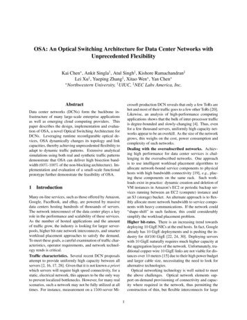
18Benton: Alignment of Optical Systems Using Lasers: A Guide for the UninitiatedFigure 11 Actions for focusing into a fiber (a) raster scanning technique and (b) lack of concentricity causes focal spot to rotate with a screw focal adjustment. When the lens is moved it rotates the focused beam around the optical axis(see Fig. 11). Operate in whole turns so that the spot returns close to itsinitial position then tweak the position to optimize. Note that you will needto use the locking ring—release, adjust, and retighten the ring—each timebecause the act of releasing the locking ring relaxes the mount and movesthe spot.Once the best position for whole turns is located fractional turns that homein on the best focus can be used.This may be adequate to focus into multimode fibers, but if you are using asingle-mode fiber you will need much more precise control over the lensposition using some form of translation stage with a micrometer control.Once you get close to the correct focus you should see the power increasesignificantly, but you will also see the sensitivity of the adjustmentsincrease.When using a visible laser, there are some visual clues as to what is happening(sadly more difficult with IR). When the laser strikes the end of the fiber, the fiberwill light up along its length. This is light that is trapped in the cladding region.This at least tells you that you have found the end of the fiber! When you getclose to correct focus, you can sometimes observe a brief dip in brightness of thislight as a significant portion gets trapped in the core.To repeat a useful tip, when you have found the best focus position, fix thingsin place! This means the mounts, the posts, and locking rings.6 Aligning an Interferometer6.1 The Michelson interferometerInterferometers work by dividing light into two paths and then recombining thesepaths to produce interference. The interference intensity usually varies
Benton: Alignment of Optical Systems Using Lasers: A Guide for the Uninitiated19Figure 12 An example optical setup for a Michelson interferometer.sinusoidally with path length difference between the two paths (usually referred toas arms). This sinusoidal variation can be seen either spatially as fringes, or temporally as a varying intensity level. When light from the two paths recombine, weare repeating our earlier task of overlapping two optical axes and we must do thisto ensure interference. Let us start with the Michelson interferometer (see forexample Ref. 7). Our task here is to use a beam splitter to divide an input laserbeam and then use two mirrors to form the two arms of the interferometer andredirect the light back into the beam splitter, combining the light that exits in athird direction where it is detected by a detector, as shown in Fig. 12. Again start with the dog leg arrangement to introduce light into the interferometer and you should use apertures to define the height parallel tothe optical table.Introduce the beam splitter, in this case a cube, and work with the beamthat passes straight through (arm 1).Using a mirror reflect the light back toward the cube.Place a detector to catch the return beam that is reflected by the beam splitter cube.Repeat for arm 2, ensuring the beams from both arms meet at the detectorby steering using the mirror in arm 2.As long as the beams from the two arms overlap on the detector, interference should be observable. This is made possible by two convenient factsthat make this experiment suitable for undergraduates.ࢤ We can use a large area detector that can detect the whole laser beam.
Benton: Alignment of Optical Systems Using Lasers: A Guide for the Uninitiated23ࢤ Adjust M2 so that spots overlapand as you close in you start to see interference fringesࢤ The fringes should get larger and pass through less quickly as you getcloser to the position of best alignment.The curvature of the fringe shows you the direction you should move thespots as you should be aiming for the center of a set of circular fringes.If you cannot see interference fringes then you have not actually overlapped the beams from the two interferometer arms (You have overlappedthe spots at the position you are observing but not matched the beam directions through the interferometer). If the distant spots are overlapped, thenobserve the spots at the detector position and you will probably see thatthey are not coincident. The beams from each arm are not collinear andcannot interfere—they are in different spatial modes.11 To correct this, weneed to physically translate one of the mirrors so that the beams travel inthe same direction as they exit. Keep checking the spots at the detectorand then further away as you move the mirror a small amount. When theylook like they overlap then fix the mirror down and repeat the alignmentprocess by looking for interference fringes.ࢤ An extra layer of difficulty appears, if we introduce a lens before the interferometer to focus onto the detectors (this will improve the field of view of the system).The smaller spots that arise from focusing require a much more precise level ofalignment to ensure that they overlap—it might sound obvious but with a largedetector then both spots could be striking the detector area but if they are notoverlapping there will be no interference. The spots are only small at the detector,when you move back some distance the spots are much larger, therefore dimmerand produce linear fringes.As a final comment, it is worth noting that this interferometer has two outputports which means that using a single-port wastes half of the light/signal.Detectors can be placed at both ports to collect all the light and if the detectorsignals are subtracted (a balanced detector) the common noise is reduced andthe signal is doubled because the light from each exit port is in antiphase—I leavethis as an exercise for the reader!7 Aligning with LensesAligning and defining the optical axis is best done with “passive” components suchas flat mirrors. (Note that curved mirrors are not passive as they focus light.) Inmany cases, we would want to include lenses in our system to provide a focal pointof high intensity or a position of efficient light collection. We can use the sameprinciples as before but be aware of some differences. An off-axis beam througha lens will be steered at an angle, thus it is important to centralize the beam. Thisis done at first by eye and then more precisely using reflections. Many lenses will
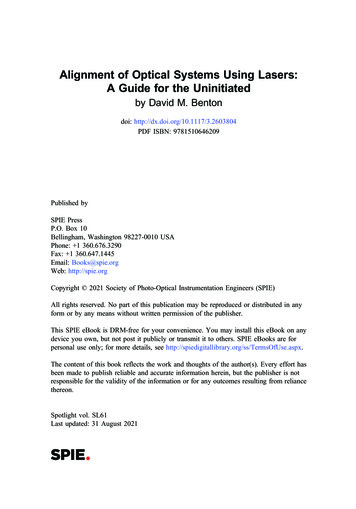
24Benton: Alignment of Optical Systems Using Lasers: A Guide for the Uninitiatedbe antireflection coated but will still have some residual reflected light we can use.The reflections from an initial convex surface will produce a large expanding beam,and the second surface, depending on its shape, may do the same. When the beamis off axis, there will be several beam spots reflected and our task is to overlap themwith the incoming beam at the center of the pattern. A horizontal and verticaladjuster on the lens allows precise overlap to be achieved. Often there will be aneed for more than one lens—such as for use as a beam expander—and this willrequire the overlap of reflections from many surfaces. Always work on one at a timeand align that one item to your previously aligned optical axis. Remember thatchanging wavelength will likely require a change in the longitudinal focal positionof the lens and quite probably a tweak of the alignment.8 The Shearing Interferometer for Testing CollimationIn Section 3.3, I discussed collimating a beam whereby we seek to produce parallel wavefronts and reduce the beam divergence. It was mentioned that precisedetermination of the collimation state of a beam must be performed interferometrically. The shearing interferometer (also called the shear plate interferometer) is adevice which can do just that and is commercially available. The device makesuse of reflections from surfaces on a glass plate producing two displaced but overlapping beams as can be seen in Fig. 17. At the overlap of the beams, an interference pattern is produced and the nature of this pattern is used to determine if thebeam is collimated. If the plate is wedged slightly, the interference fringes produced will vary in the direction of the wedge, usually orthogonal to the directionof the shear. Beams with residual focus will have fringes aligned at an angle.9 Alignment of Near-Infra-Red BeamsConventional optics made from silica (glass) will have a transmission spectral profilethat extends to nearly 2 μm in the near-infra-red (NIR). Thus a system that will operate in the NIR, such as a telecoms system at 1.5 μm, will be able to transmit visiblelight. The optical components themselves may well be coated to reduce reflectionsbut they will still transmit a visible beam. Aligning a system with a beam you cannotsee is an extremely difficult task, so the most sensible approach is, do not do it! Align the system components using a visible laser. This will at least allow youto get the components and thereby the optical axis established and aligned.Active elements such as lenses, even achromatic lenses, will focus in a different place for visible than for the IR. However when the axis is aligned,you know that you will require a change in focus only.NIR systems may well contain optical fibers. Thus you will need to get thealignment laser into the system. By far the easiest way to do this is with alaser, such as a diode laser, that is coupled to a fiber pigtail, which willallow you to just plug it into the system (This is actually a very useful
Benton: Alignment of Optical Systems Using Lasers: A Guide for the Uninitiated25Figure 17 (a) A diagram of a shearing interferometer used for collimation testing and (b) theinterference patterns seen when the beam is collimated or has some focus. laboratory tool anyway as it provides a clean beam that can be used formany alignment tasks). Without this, you will need to revert to focusinga laser into a fiber yourself as in Section 5.In some cases, even a visible alignment laser is not the complete answer—for example, if you are using a diffraction grating where light comes off ata different angle. In such cases, you will need a method of viewing wherethe beam is. This is often done with an IR viewing card. This uses aphosphor which absorbs IR light and glows in the visible. This can givea diffuse indication of the size and position of the beam. The phosphor willneed “recharging” with visible light every few minutes. Another option isan IR viewer similar to a night vision device which can provide an imageof where bright IR spots are located.Bear in mind that detectors that see visible light will most likely not seeNIR light and vice versa, so you will need to switch between detectors asyou switch between wavelengths.10 The Retroreflector as a Useful ToolA retroreflector is an optical element that reflects light back in the same directionthat it originated. The effect is seen with highly reflective clothing or road signs
Benton: Alignment of Optical Systems Using Lasers: A Guide for the Uninitiated31David Benton graduated in Physics from the University of Birmingham in 1989.He completed a PhD in laser spectroscopy for nuclear physics in 1994 and thenconducted postdoctoral research in positron emission tomography and then laserspectroscopy for nuclear physics, all at the University of Birmingham. In 1998he joined DERA which became QinetiQ where he worked on a variety of opticalprojects. He was the leader of a group building quantum cryptography systemsand was involved in a notable 140km demonstration in the Canary Islands. Hebecame Chief Scientist for L-3 TRL in 2010 working on photonic processingtechniques for RF applications. He is now at Aston University with a variety
1.1 A word about laser safety 2 1.2 Laboratory good practice 2 2 How Alignment Can Go Wrong 2 2.1 Basic alignment 3 2.2 Elemental components and controls 4 3 Working with Lenses 5 3.1 Lens action 6 3.2 Focal spot size 6 3.3 Collimation 7 3.4 Divergence reduction using beam expanders 9 3.5 Gaussian beams 10 3.6 Chromatic aberration 11