Transcription
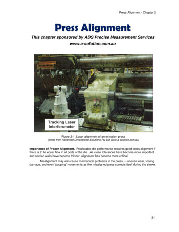
Press Alignment - Chapter 2Press AlignmentThis chapter sponsored by ADS Precise Measurement Serviceswww.a-solution.com.auFigure 2-1: Laser alignment of an extrusion press(photo from Advanced Dimensional Solutions Pty Ltd, www.a-solution.com.au)Importance of Proper Alignment. Predictable die performance requires good press alignment ifthere is to be equal flow in all ports of the die. As close tolerances have become more importantand section walls have become thinner, alignment has become more critical.Misalignment may also cause mechanical problems in the press --- uneven wear, toolingdamage, and even “popping” movements as the misaligned press corrects itself during the stroke.2-1
Press Alignment - Chapter 21,2,3,4Alignment Principles.The geometric or dimensionalaspects of an extrusion pressare fundamental to properpress alignment, which isrequired for maximumproduction quality andminimum downtime. The pressshould be installed accordingto the original manufacturer’sspecifications, especially withrespect to tolerances. If theirrinstructions and recommendedprocedures are carefullystudied, the ideal 3-Dgeometric relationship of thepress components can bedetermined. In general, themain 3-D geometricrelationships of the staticcomponents of a simpleollows:extrusion press are as follows: the press base orbedplate should belevel with respect togravity, and therelevant contact pointsshould lie in a flatplane. the back or resistanceplaten should be fixedperpendicular and thefront platen locatedperpendicular to thebase, withh both platensparallel to each other.Sponsor’s advertisement www.a-solution.com.ausolution.com.auInformation: ADS@a-solution.com.ausolution.com.auTelephone 61.4.38412865 the pressure ring bushing should have its hole centered in the front platen with its frontsurface flat and parallel to the front platen. the guide ways for the crosshead and container should be straight and parallellongitudinally to the base, and should be symmetrically spaced about the press centerline with the correct dimensions.Information in this chapter is largely derived from the following papers:1Mulder, Joseph E. V., and Smith, Gavin J., “Extrusion Press Alignment with ModernTechnology,” Proceedings of 7th International Aluminum Extrusion Technology Seminar,Vol I, (2000), p.455-463463.2Anthofer, E.J., “Press Alignment,” Proceedings of 2nd International Aluminum ExtrusionTechnology Seminar, Vol. I, (1977), p. 169-173.3Freese, Howard W., “Alignment of the Extrusion Press,” Proceedings of 3rd InternationalAluminum Extrusion TechnologTechnology Seminar, Vol. I, (1984), p.105-111.4Bergman, John, “PressPress Alignment Using 3D Laser TechnologyTechnology,” presented at AEC PressMaintenance Seminar, (2002(2002), Chicago.2-2
Press Alignment - Chapter 2 the main cylinder, bearing bushing, flange, and ram piston should be concentric andcenterd on and perpendicular to the back platen. the crosshead should be center-mounted on the ram and fitted with a straight andcentered extrusion stem perpendicular to the back platen. the press center line is the line joining the platen centers, and all the platen-centeredcomponents should lie on this line. the geometric center lines of each of the four machined tie rods or columns should beparallel to and symmetrically located about the press center line so that their mean isparallel and lies on the press center line.It is clear that, as more components are added, a more complete 3-D model is built upequivalent to the original design drawings and, with the specified tolerances and criticaldimensions, that this is the mathematical inspection template used during measurements forcompliance of any of the press components.Similarly, the 3-D geometric relationships of the moving components of the press are asfollows: the ram piston and the extrusion stem move along the press centerline over their fullstroke. the center line of the container bore is coincident as it moves along the press center linefrom its open to closed position, under container pressure and during various extrusionloads. the centerline of the tooling stack is coincident with the press center line in its closedstate, under container pressure and during various extrusion loads. the billet loader positions the billet so that its centerline matches the centerline of thecontainer and stem before it is loaded into the container.These relationships must be correct when the press is at operational workingtemperature to allow for thermal growth effects. The above also implies that some sort ofmonitoring process of the major press components should be carried out during the variousoperational load and event conditions of ram and container pressure and extrusion.2-3
Press Alignment - Chapter 2Alignment ProceduresThe procedures and frequency for press alignment will vary according to the press designand condition and the quality control procedures of the plant. The original recommendations ofthe press manufacturer, if available, should always supersede the procedures described below.However, in the absence of complete alignment instructions from the press supplier, these will behelpful in setting up an alignment program.Press Alignment procedures may be divided into two parts: Alignment of the main press frame and components, which must be carried out veryprecisely when the press is first installed; again after any period of neglect, for example,when beginning a new program of regular preventive maintenance; and recheckedperiodically thereafter. Routine re-alignment of wearingcomponents, which frequently vary due tosteady wear and tear or replacement ofcomponents.Laser alignment tools and methods areemerging as the best technology for quick andaccurate press alignment, often replacing themechanical devices used since the 1950’s. Atthis time the laser tools may not be available toall extruders, so both types will be presented inthis chapter.Recommended ToolsThe tools recommended for performing pressalignments may include the following:Machinist’s Level. A precision type level, itshould have minimum 10-second accuracy (onedivision equals 0.0005 inches/foot or0.004 mm/Meter). Do not use onhot surfaces!Figure 2-2: Three-plane laser level(See www.hamarlaser.com)Surveyor’s Precision OpticalLevel (Transit). Typical accuracy is0.0001 inches/foot.Laser Level (1, 2 or 3 Plane). (Nowcommonly used in place of transit.)The 2- or 3-plane lasers will requirefewer set-ups to complete theleveling. (Figure 2-2)Trammel Rod. These are custombuilt devices designed for measuringthe distance between platen flanges(or between tie-rod nuts). A steel oraluminum tube is fitted with an insidemicrometer or dial indicator on oneend, and a spherical-ended pin onthe other (see Figure 2-3). Foraccuracy, the trammel rods must bedesigned and supported to avoiddeflection from their own weight; andinsulated to avoid expansion fromFigure 2-3: Trammel Rod device.Figure 2-4: Container Taper Gauge2-4
Press Alignment - Chapter 2heat transferred by the press container heat.Container Taper Gauges. Custom-made gauges as shown in Figure 2-4 are fabricated of aneasily-scribed material such as aluminum, about 6 inches long with angle taper slightly greaterthan the taper of the container inlet or taper seal taper. Scribed marks indicate the accuracy ofram centering within the container.Adapter Blocks forAngled Guideways (tworequired). For pressesequipped with angled guideways, these custom-madeadapter blocks (Figure 2-5)provide proper referencepoints for leveling of thepress frame.Piano Wire (or MusicWire). Diameter 0.4 mm to0.5 mm (0.015” to 0.020”);tensile strength 250,000 to500,000 psi (1700 - 34002N/mm ).Figure 2-5: Adapter Block for Angled Guide Ways.Fixtures for Piano Wire Tensioning. Use of music wire for locating the press center line maybe simplified by use of custom-made fixtures as shown in Figures 2-6 and 2-7, for tensioning andpositioning the wire at the press platen and ram stem.Figure 2-6: Alignment with piano wireFigure 2-7: Fixtures for alignment with piano wire.2-5
Press Alignment - Chapter 2Precision Tube Fixture. Alternativealignment techniques may use acustom-machined tube, along withfixtures for the press platen and ramstem, as detailed in Figure 2-8.Base Centerline Fixtures. Anothersystem uses precisely located holesin the press base, along with specialfixtures as detailed in Figure 2-9.Dummy Dies and Tooling Stack.An alignment tooling stack with anappropriate center hole (Page 2-11)is used for checking centering to thecontainer, stem, and pressure plate.An alternative type of dummy diewith precision scoring (shown inFigure 2-12) may be used to quicklymeasure tooling-to-containeralignment.Figure 2-8: Precision Tube FixtureThe following additional standardmeasurement tools arerecommended:Dividers*, Calipers*, andHermaphrodite Calipers*Precision Square*Straightedge* (typical 8 feet long)Plumb Bob*Figure 2-9: Fixture for Base Centerline MethodFeeler Gauge*Note: the items marked (*), plus the music wire, machinists level, surveyor’s level, and insidemicrometer for trammel rod, are generally available from tool suppliers; for example, fromMcMaster-Carr Supply Co., PO Box 4355, Chicago IL 60680-4355, Telephone 312-833-0300,Fax 312-834-9427, www.mcmaster.com.2-6
Press Alignment - Chapter 2Alignment and Leveling of the Fixed Press ComponentsThe press base must first be square and level. When first installed the press base isusually set on shim packs on top of the press foundation, leveled, and then grouted in place.Normally, ½” to 1½” of grout is used. Anchor bolts should be tightened against the shim packs,which are located on both sides of each anchor bolt to avoid distortion of the frame. Levelingaccuracy is normally 0.0005 in/ft (0.04 mm/meter).With the passage of time, it is possible that the press base is no longer level. Possibleproblems include: settling of the foundation or the soil underneath deterioration of the foundation deterioration of the grout loose anchor bolts environmental conditions modification or mechanical damage to the press frameBefore leveling the press base, the condition of the grout and foundation and thetightness of anchor bolts should first be checked. If necessary, remove the grout; re-level andshim the base; re-tighten the anchor bolts; and re-grout. If the levelness continues to change dueto foundation deterioration or settling, consult a geotechnical engineer concerning moderntechniques of foundation repair, such as pressure grouting and grout pilings. Once correctlyadjusted and stabilized, re-checking of the press base should not be required except at infrequentintervals unless there are unusual foundation problems.It is also important to insure that tie rod nuts are tight and that the tie rods and nuts arenot cracked. Any looseness will affect measurements.1. Level the Press Base in all directions. Check the level lengthwise, then across the base,and then diagonally both ways (left front to right rear, right front to left rear). The desired variationfrom true level is maximum 0.0005 inches/foot (0.04 mm/meter). Re-level the base if it exceeds0.0030 in/ft (0.25 mm/M) from true level.The guide ways are the preferred reference points for leveling. In case of angledguideways, use the Adapter Blocks for Angled Guideways (Figure 2-5) to establish horizontalsurfaces for use in leveling.Measure 12 to 14 points along the length of each guideway. If using a laser level,measure along both the inside and outside of each way. First choose one way as a referenceplane and then measure all other points against the reference.2. Level and align the Main Cylinder. The platen or flange portion of the main cylinder must beperpendicular to the guideways and the centerline of the press base, and parallel to the frontplaten. To measure, place a precision square on the machined front surface of the platen, andcheck the horizontal leg of the square with the machinist’s level. Maximum allowable variationfrom perpendicular: 0.0005 in/ft (0.04 mm/meter).If using a 3-plane laser, measure the angle between the reference guide way and themain cylinder and front platen, in order to determine their squareness to the reference guide way.Another important check: extend the main ram just far enough to accommodate themachinist’s level on the ram surface (about 18”). At this point the main ram should be fullysupported by the main ram bearing bushing. The main ram should be level to the sametolerance: 0.0005 in/ft (0.04 mm/meter). If the main cylinder’s platen surface is perpendicular andthe ram is not level, the main ram bearing bushing is likely worn and may require replacement.The guide shoes of the moveable crosshead should just be touching the guide ways in thisposition.2-7
Press Alignment - Chapter 2On some presses the perpendicularity of the main cylinder platen may be adjusted byjacking and shimming the rear cylinder support.3. Check the levelness of the tie rods. Check the level in both directions -- along each tie-rodand across both the top and bottom sets of tie-rods at each end. The tie rods should be level tothe same tolerances as the press base: 0.0005 in/ft (0.04 mm/meter).4. Check that the Front Platen and Main Cylinder Platen are parallel. Distance between thetwo platens should be measured at each tie-rod, with the container at operating temperature.Measurement is made with the trammel rod (Figure 2-3), always measuring between machinedsurfaces. In some cases it may be easier to measure between the inside tie-rod nuts; in this caseyou will always measure the thickness of the nuts with a micrometer and add these dimensions tothe trammel rod measurements.Always support the trammel rods from the tie rods with “S” hooks to avoid deflection, andinsulate the rods to avoid expansion due to heat from the container.Maximum variation will depend on manufacturer’s recommendation; in absence of thisinformation, the maximum allowable variation between tie-rods should be 0.003 inches(0.075 mm). This measurement should be repeated under both no-load and loaded conditions.Newer presses may have the tie rods encased in sleeves, which are machined to exactdimensions. In this case, the platens should always remain parallel, and it is not necessary tocheck the “tram.”5. Check the pre-stress of the tie-rods. Follow the press manufacturer’s instructions forloosening the nuts and adjusting the prestress of tie rods. In the absence of such manufacturer’sinstructions, the following general procedure may be useful:Prestressing of tie rods is usually accomplished by raising the press tonnage to 10%above the rating, using the main ram to stretch the rods, and then tightening the inside nuts andlocking them to retain the prestress.The inside nuts should remain tight, even under full load, and should not allow insertionof even a 0.001 inch feeler gauge (0.025 mm) between the nut and flange. Likewise when theload is relaxed there must be no clearance between the platen and outside nuts. With sleevedtie-rods, no space is permitted between the sleeve and platen. Any such space indicates a lossof pre-stress and requires re-torqueing of nuts and rechecking of squareness.2-8
Press Alignment - Chapter 2Alignment of the Moving Press ComponentsThe so-called “dynamic” press components are cycled many thousands of times in atypical month and so are subjected to wear, as well as to heating and mechanical shocks.However, while your press has grown older and wear has accumulated, your customers’demands for profile tolerances and wall thicknesses have become more difficult. Alignmentbetween container, die, and platen pressure ring are more critical than ever. Following are therecommended procedures:1. Check the level and alignment of the main ram and ram stem. Check that the main ramremains level and aligned with the press centerline (in the plan view) throughout its travel. Onmost presses adjustment is made through the guide shoes of the moveable crosshead. It isrecommended to check at least 3 points of the travel. Level may be checked on the main ramwith the machinist’s level or the surveyor’s level. It may also be checked on the ram stem afterdetermining that the ram stem is both straight and parallel with the ram, and that the stemretention devices are properly tight.Alignment in the plan view (left/right) is checked by first establishing the press centerlinewith a piano wire and using a plumb bob at three points along the ram stem travel.If using a laser level, attach a receiver to the ram and track it throughout its entire stroke.The stem can then be tracked in the same way.2. Check the alignment between the front platen pressure ring, die stack/die changer,container, and ram stem. There are several different procedures and fixtures for you to choosefrom, for measuring the relative alignment of these elements. You will probably use acombination of the following:A. Aligning moving components with laser. The laser can be used to find the centerof the die stack in relation to the pressure ring opening. A clear die stack such as thealignment tool stack will make placement of the receiver units easier. In a similar mannerthe stem’s centerline may be checked relative to the pressure ring and tooling stack;check it at various positions for the stem. Finally, the centers for the front and rear of thecontainer may be checked if cold – if hot the laser beam will be distorted and inaccurate!For this check the sender is placed in the container bore and the receiver on the stem.B. Locating the die stack position by use of an Alignment Tool Stack: While it istheoretically possible to measure the die location from the surfaces of the die carrier ordie changer pocket, in practice it is recommended to use an alignment tool stack (pages2-11 and 2-12) for more accurate measurement of centering. In every case, you shouldcheck both sides of the double die slide, or both die carriers if fitted with unistationor rotostation die changer.C. Locating reference centers with the Piano Wire method: You should have alreadyestablished the correct alignment of the ram stem and front platen. Next a piano wire isplaced in tension along the press centerline, according to Figures 2-6 and 2-7. Thespecial Front Platen Centering Fixture and Ram Stem Anchor Plug are installed and usedto apply tension to the piano wire and establish the center reference for checkingalignment of the die stack/die changer and container.D. Locating reference centers with the Precision Tube fixture: The Precision TubeFixture shown in Figure 2-8 may be used to establish reference centers for alignment ofthe die stack/die changer and container. The wall thickness of the precision tube isselected to insure minimum normal sag even after it is machined and ground forstraightness. For example, a 4-inch OD tube (100 mm) with wall thickness 0.250 inches(6 mm) will sag only about 0.001” (0.025 mm) in a length of 9 feet (2.75 meters).The tube is fitted with end plugs that have locating centers as shown. Fixturesare shown for supporting and aligning the precision tube at the ram stem and front platen.2-9
Press Alignment - Chapter 2Note that the centering fixture for the front platen is fitted with an adjustable stiff spring,which accommodates expansion of the tube due to heat from the container.E. Locating reference centers with the Base Centerline system. This methodcreates two precisely located holes in the press base, which are then used for accurateplacement of a special taut wire system for checking centerline distances (figure 2-9).(Some press bases may not be suitable for this method, depending on the design of thepress base.)To establish the base centerline, the tie-rods are used as a reference and a tautpiano wire is wrapped in criss-cross fashion as shown in Figure 2-10. Then a plumb bobline from the intersection of the crossedwires is used to locate centerline pointson the press base. Two holes are drilledand reamed at these points: one 0.50 in(12 mm) and the other 0.75 in (19 mm).The two surfaces used for these holesshould be approximately level with eachother. Special wire holders (as shown inFigure 2-9) fit snugly into these holes toestablish a taut wire centerline.One wire holder is adjustable forheight, the other one for wire tension.The wire is brought to true level,tolerance 0.0005 in/ft (0.04 mm/meter);level may be quickly determined byplacing a straightedge across the wireholders and using the machinist’s level.(The vertical distance “D” from the wireto the leveling surface should bemachined the same on both wire holders.)Figure 2-10: Locating the Centerline of thebaseF. Checking clearance between Container and Ram Stem with taper gauges. Thealuminum taper gages shown in Figure 2-4 are used as illustrated to check centering ofthe ram stem within the container opening. The gauges should be placed on the ramstem surface and against thecontainer opening. The point ofcontact with the container opening,as compared with the inscribedomarks, is checked at 4 points 90apart around the ram stem.Clearance between ram stem andcontainer should not vary morethan 0.020” (0.5 mm) around thestem. This clearance should bechecked at both ends of thecontainer.Note: similar taper gaugesmay be used with the PrecisionTube Fixture system describedabove.G. Reference Dimensions forthe Container Centers. Becausethe actual openings of thecontainer may contain nicks andirregularities, it is recommended toFigure 2-11: Locating the container centerlines2-10
Press Alignment - Chapter 2locate reference measurement points on the container faces. A center punch is used tolocate reference marks at fixed distances from the actual center, on both the vertical andhorizontal axes. Reference points should be marked on both the front and backcontainer faces. Measuring from these points to the taut wire or precision tube describedabove is much easier and more accurate.3. Adjusting the Alignment of the Container and Tooling Stack. The target alignmentaccuracy between the container and tooling stack in all directions is 0.020” (0.5 mm). Caution:when using taper seal dies, exact vertical alignment is desirable, but the container should neverbe below the die centerline, in order to avoid upward thrust loads to the die stack and die carrier.Adjustment procedure varies according to press design, and there are many differentsystems. The die stack must be at operating temperature. Most commonly, the die stack is firstadjusted to match the pressure ring. Lateral adjustment is made by moving the threaded stop ofthe die changer. (Unistation and rotostation changers use a single stop for both die carriers, sothis adjustment is made easier and more accurate.) Adjusting the die position vertically is moredifficult; while a few presses have built-in adjustment, on most it is necessary to vertically shimthe guide ways or “gibs” of the die changer.Next the container must be adjusted to align with the die stack and also the ram stem.Once again, the container and die stack must be at operating temperature. Container adjustmentis made with the adjusting screws on the guide shoes. Presses with center guides (top orbottom) and “X” or angled guide ways pose the greatest problems in making accurateadjustments, due to difficult access and the indirect nature of angular adjustments. Considerationshould be given to retrofitting the press with guides which permit “logical” vertical and horizontaladjustments. (See page 2-15 and also Chapter C: Modernizing Older Presses.)4. Alignment of the Butt Shear. On smaller presses (below 1800 Tons), the shear adjustmentshould place the shear blade 0.020” to 0.025” (0.5 to 0.6 mm) from the hot die face. On largepresses this clearance may increase to as much as 0.125” (3 mm). However, the dimensions ofthe die stack must first be standardized and the position precisely assured by the position anddimensions of the die carrier or die changer pocket (and clamp if available).While many press operators operate with greater clearances, due to sloppy diedimensions and worn or loose parts, the result is a great risk of mechanical failures or collisions,and failure of the butt to separate from the blade properly.The method of adjusting blade clearance varies according to the press design, butnormally it is required to add or remove shims between the blade and its holder to achieve thenecessary dimensions.5. Alignment of the Billet Loader. The container, ram stem, and fixed dummy block must all beat operating temperature. Alignment accuracy of 0.020” is recommended. Preliminarymeasurements may be made by any of the alignment systems described previously, but shouldthen be checked with an actual billet or full-size dummy billet, and with the container in the sealedposition. The means of adjustment varies according to the design of the billet loader and press.Alignment should take place with the loader raised to the loading position, then blocked inplace with a heavy timber in case of power or control failure. Presses which still use loosedummy blocks should be checked with a loose block on the billet loader.2-11
Press Alignment - Chapter 2Use of the Alignment Tool Stack5The advantage of having an alignment tool stack isthe ease that is made of checking press alignment,the die stack alignment to the pressure plate boreand the stem alignment to the container bore.The alignment tool stack is made to the sameoutside dimensions as the die stack and bolsterstack. The bore is made to the same internaldimensions as the container bore and the pressure plate hole.When the alignment tool stack is sitting in the die holder with the container sealed, you can lookthrough the platen hole and check the alignment of the container to the die stack.The stem should then be brought forward without the alignment tool stack, to the entrance of thecontainer, and held so that the stem can be checked for alignment to the container bore. Thestem should then be brought forward to the end of the stroke. It should be on center all the waythrough the container. If not, the stem is out of alignment.Press AlignmentMost often the problem is not a single one, but a number of small ones which add up to a majorproblem.Problems with press alignment can often start from the press foundation and bed, which canmove over time from normal use. Foundation bolts and shims can become loose, allowing thepress to shift.Some presses are supplied with a pair of alignment blocks. In this case, the ways are on anangle and the alignment blocks can be placed on the ways with a straight edge and machinerylevel. This will soon tell the story (of course, more efficient lasers can be used if available).Should the bed of a press be out of level, problems will multiply as you proceed with alignment.5Pages 2-11 and 2-12 are taken from Castool Bulletin “Alignment Tool Stack.”2-12
Press Alignment - Chapter 2The tie rods should be checked and maintained within .005" (.127 mm) in all directions.The main ram (with level bed) should be moved out approximately 30" (750 mm) and amachinery level placed on top of the ram. The ram can then be leveled with shims under themain ram shoes. If the stem is not level, both the crosshead pressure plate and the stem shouldbe checked.With the alignment tool stack installed in the die slide, align the pressure platen hole andcontainer bore to the alignment tool stack. If you have misalignment between the container andthe alignment tool stack, check the die changer for height and the base of the die changer forlevel.The alignment tool stack should then be removed from the die carrier and the stem movedforward and centered to the container bore (a taper wedge is useful for this purpose). Lookingthrough the platen, the stem should then be moved slowly through the bore of the container; itshould be in the center of the bore all the way through.After the stem is aligned, align the billet loader so that the plates are approximately 0.020"(5mm) above the bottom of the container bore.The face of the stem should be checked for mushrooming. If mushroomed, the stem must bestress relieved, checked for cracks and machined.The extrusion cycle should also be checked. The container should only open 3/4" to 1" (20 to 25mm) before the main ram starts to retract. This is usually accomplished by adjusting limitswitches. This will reduce the damage caused to the alignment tool stack and container faceduring the ram return.Many problems are caused by aluminum build up on the sealing face of the container or the die.This may be due to poor butt shear adjustment, bad loader alignment, or a butt lodging betweenthe container and the die which forces the container to move. A tilt switch can be installed tostop serious damage to the stem and the loader if this occurs.Another area which should be examined is the main ram bushing and the main ram packing. Ifthere is wear in this area there will be signs of oil leakage and the stem will be out of parallel. Aoshort term solution is to rotate the bushing 180 .2-13
Press Alignment - Chapter 2Quick Checks of Press AlignmentFollowing are two procedures which may be used for quickly checking alignment betweenthe press container and die stack, for example, in the case where daily monitoring of alignment isdesired.1. Checking alignment of Container with Die Stack by means of a Scribed Blank Die. Afast check of the most critical alignment -- between the die and container -- may be made withonly a brief operating pause, by means of the Scribed Die Blank as shown in Figure 2-12. Thespecial die is loaded into the die changer and used with a 2-inch thick (50 mm) billet slice, whichmay be hand loaded into the container (cold). After suitable press tonnage is applied to theblank, the upset billet slice is retrieved and set aside for measurement. Centering is easilymeasured at the peripheral ring and “cross-hairs”. Each die carrier or die slide pocket should bechecked i
Press Alignment - Chapter 2 2-1 Press Alignment This chapter sponsored by ADS Precise Measurement Services www.a-solution.com.au Importance of Proper Alignment. Predictable die performance requires good press alignment if there is to be equal flow in all ports of the die. As close tolerances have become more important