Transcription
Siderotype Workshop NotesPreparation of Digital .ukMIKE WAREBUXTONDERBYSHIREUNITED KINGDOM
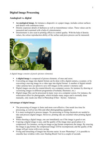
Alternative Photographic Processes: Digital Negative Workflow Mike Ware 2012Preparation of Digital NegativesSummary and purposeHerein follows a stepwise sequence of explicit instructions for makingmonochrome digital photographic negatives, using a personal computer andink-jet printer, starting from original medium format camera negatives ortransparencies, or from digital picture files. The software used for this imagemanipulation is Photoshop CS (Version 8) and Epson Scan, using an iMac,running OS 10.4. No additional software or ‘latest upgrades’ are required. Thefiles are printed out onto ceramic-coated transparency material (such asPictorico OHP Transparency Film or PermaJet Digital Transfer Film)1 using anEpson photo-quality ink-jet printer. This provides internegatives suitablymatched in ultra-violet optical density for contact printing in any of the‘alternative’ photographic processes. This digital negative workflow differssignificantly from the customary practices of others in several respects: For calibration, 100-step-tablet negatives having intervals of 1% relativeopacity, are inkjet-printed onto the film, identical in all their printparameters and materials with the actual negatives to be output.2 All thecolours of printer's ink-set are used, mixed in a smooth greyscale. The Standard Printing Exposure (SPE) is found by exposing these 100step-tablet negatives in the process of choice with the standard printingsetup, so that the clear filmbase (relative opacity of 0%) produces ‘nearly’the maximum print density (Dmax) that the process is capable of, whileoffering some tonal separation in the deepest shadows (0-10%). The correct ink density range (at UVA wavelengths) for the negative tomatch the exposure scale of the given process is found by adjusting theprinter driver settings: trial 100-step-tablet negatives are output andtest-printed at the SPE, until the 99% relative opacity step in the negativeprints as ‘just white’ background of the paper chosen for the process. Having established the 'black and white' end-points for the process, whenmaking the negatives appropriate for analogue printing, the image levelsare redistributed in Photoshop simply by the gamma slider in the Levelswindow, which applies a suitable 'generic curve' /?no cache 1&L al-Transfer-NegativeFilm-165uThe .tiff file for this 100-step-tablet may be downloaded directly tif12
Alternative Photographic Processes: Digital Negative Workflow Mike Ware 2012Calibration of the equipment and materialsThe optical density range of the ink laid down on the film depends on: the particular make and model of printer the particular ink set being used the choice of settings in the printer driver software the film substrate used to receive the negative imageIf any of these are changed, it will be necessary to re-calibrate.1) Output the digital file for the 100-step-tablet to your printer.Load the printer with the identical film that you will use for all your negatives.As a starting point, the ink density range may be approximately provided by theprinter’s ‘premium photo-quality’ media settings for glossy or semi-glossypaper. The software for driving modern printers now usually includes a meansof adjusting the maximum ink density; this control may be buried rather deeplyin the options. Record its setting before outputting the 100-step-tablet files.Let the test negative dry and cure overnight before use, as inks have beenobserved to change density with time.2) Use the standard print-making setup for your chosen process.Take care that the light source, distance, and other conditions of printing andwet-processing are maintained constant throughout.3) Use your 100-step-tablet negative to make trial contact exposures.Increase the exposure if necessary, until you have a test print that is perceptiblyoverexposed. [N.B. 'Overexposure' here is judged by the analoguephotographer's criterion of shadow tones beginning to 'block up' and becomeindistinguishable – it is NOT judged by the digital photographer's criterion ofhigh values becoming 'blown out'.]Call the exposure for this test print, E. If you are making timed exposures to aconstant light source, E is simply the duration in minutes or seconds. If youemploy an exposure system with a light integrator, E will be measured in theinstrument's arbitrary 'exposure units'.4) Examine the test print carefully when it is dry.The lowest part will appear dense and ‘blocked up’ with no resolution of thesequential steps. Compare each step with the lighter one immediately above it i.e. the one resulting from 10% less transmittance in the negative ( 10% moreopacity, which corresponds to an optical density difference of ca. 0.05, or onesixth of a 'stop').Try to locate the first step, starting from the bottom, that is just perceptiblyresolved in tone from the one above it; this lower step tells you thetransmittance in this negative needed to produce your effective maximum printdensity. Call this transmittance P%.5) Calculate the Standard Printing Exposure (SPE).Take P% of E, the exposure for the test print made in 3):SPE E x P/1003
Alternative Photographic Processes: Digital Negative Workflow Mike Ware 2012This SPE should apply approximately for all prints made in the chosen process,with your digital negatives, provided that the light-source and other printingand processing conditions are kept the same.Note that the SPE is not sharply-defined, but can be varied slightly, because theeffective maximum print density depends on how far up the shoulder of thecharacteristic curve of the chosen printing process it is placed. However, thehigher the effective maximum density is placed, the more of the 256 imagelevels will need to be allocated to increasing separation in the shadow tones, sothere will be fewer left for the lighter tones of the image, which compresses thecontrast. Furthermore, if you seek to produce a 'maximum black' by extendingthe SPE excessively, the printer inks may not have sufficient UV blocking opacityto produce a 'paper base white' at all.6) Make a contact test print of the 100-step-tablet negative at the SPE.Inspect the test print carefully, when fully dry, to find the step that appears ‘justwhite' - i.e. the first one that has no upper boundary and which precedes thestep with the first perceptible print tone.7) If no steps print white, adjust the printer driver settings to lay downmore ink when making the negative.If several steps print white, adjust for less ink in the negative.8) Return to Step 1) and make a new 100-step-tablet negative.Use the new settings, and re-test it through Steps 2) to 7). The ideal aim is toget 'just white' for the first step of the tablet - that having 1% transmittance or99% opacity – but it should be satisfactory to get within 2 or 3 steps of this.Experiment carefully with your printer driver settings: change the maximumoptical density of the ink (a control usually found in the "colour management"window) and note its value when you make each new test negative. Print eachone in your process with the same SPE until you come close to the idealhighlight tones.Fine-tuning the negative opacitiesThis is only necessary in case your printer driver controls do not allow you toget the first white step close to 1% transmittance or 99% opacity. If it is stillsignificantly different from this ideal value, then it will be necessary to reset themaximum opacity of the negative file to a value equal to the opacity observedfor the first white step, before you output it on transfer film, so that thenegative will print the white level correctly. The Layer Opacity Slider in the layerspalette provides a convenient means of making this fine adjustment. All theother opacity values will then be scaled proportionally.Setting the Layer Opacity to less than 100% makes the tonal separation abit coarser in principle, because the tonal scale of the image will be resolvedacross fewer than the full 256 levels. If the printer driver settings result in awhite value close to 100%, it’s unlikely the eye will notice this, so thisadjustment in the following Workflow should be no more than ‘fine-tuning’.4
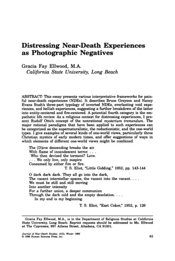
Alternative Photographic Processes: Digital Negative Workflow Mike Ware 2012Use of the 'gamma slider' for applying tonal correction curvesThere usually is a need to redistribute the levels of a digital image file before itcan be rendered as a negative useable for analogue printing. If this is not done,a print made with the SPE will usually appear too dark in overall tonality, eventhough the black and white end-points print correctly. In effect, what is neededhere is an approximate transformation of the linear scale of Relative Opacity %,used for digital files, into the logarithmic scale of Optical Density that isnecessary for a negative to yield a visually acceptable print by any analoguephotographic process having a typical characteristic response.If we are prepared to accept an approximate transformation, it becomesunnecessary to use experimentally-derived curves, with all their burdensomeand usually rather inaccurate measuring of many experimental points, becauseessentially the same result comes from re-setting one simple parameter inPhotoshop, as follows.This parameter is the middle slider in the Levels Histogram window, whichcontrols the gamma (or contrast) value shown in the central box, and whichalways has a default value of 1.0 when the window is opened. The gamma needsto be increased to a value in the region of 1.8 to 2.2 in the positive image,which – be warned! – will then appear horribly overexposed in the digital sense,or ‘blown out’ on-screen. This adjustment usually suffices to re-map therelative distribution of levels from most positive digital image files to provide,on inversion, a negative with sufficient density to be printable by analogueprocesses. This one simple adjustment with the gamma slider effectively appliesa built-in ‘generic Curve’ for transforming all digital picture files to analoguestatus. It agrees in practice with individually-derived personal correction curves,which have been scrupulously plotted by expert workers from point-by-pointreflectance density measurements of actual step-tablet test prints, making itgenerally unnecessary to derive a curve for yourself.Figure 3. Scan of a palladium print of 100 step tablets made at the SPEGamma 2.2 on leftDefault Gamma 1.00 on right5
Alternative Photographic Processes: Digital Negative Workflow Mike Ware 2012Workflow for Making Digital Negatives in Photoshop CS:Summary of the sequence of ‘Things that may need to be done’Phase I: Acquisition and Digitization of Image1) Turn off Colour Management in Photoshop2) Open Image File – if already available, or –3) Scan Source – if necessary – and SavePhase II: Preparation of Positive Image File4)5)6)7)8)9)10)11)Preliminary Image Adjustments – if neededCrop & Re-size ImageMonochromatize – if an RGB colour imageBurn & Dodge – if desired (a crude tool)Set Black & White LevelsAdjust Local Contrast – in areas where neededRetouch Flaws – where necessarySave ‘Perfected’ Positive ImagePhase III: Preparation of Negative Image File12)13)14)15)16)17)Apply Tone Correction Curve to Positive by resetting GammaReverse Handedness – if image reads correctly on screenInvert Tonality from Positive to NegativeSharpen Image with Unsharp MaskMask Print Border – if desired (expensive in ink)Flatten Layers & Save ‘Adjusted’ Negative Image FilePhase IV: Printing the Negative Image onto Film18)19)20)21)22)23)Fine-tune Negative Opacity to Match Exposure Scale - if neededConnect Printer. Load Film & Check InksSelect Printer & Page SetupReduce Image File to 8 bits per channelSet Printer Driver & Maximum Ink Density & Output the NegativeNumber the Negative & allow ink to cure6
Alternative Photographic Processes: Digital Negative Workflow Mike Ware 2012Workflow for Making Digital Negatives in Photoshop CS:Phase I: Acquisition and Digitization of ImageKeyMenu or ToolProcedureKeys are Shortcuts to Tools and Menus: my F6, F7, F8 are re-defined: Edit Keyboard Shortcuts1) Turn Off Colour Management in Photoshop KPhotoshop Colour Settings RGB:CMYK:Gray:Spot:Colour Management Policies:In order to turn Colour Management OFF:‘Monitor RGB – iMac’‘Euroscale Coated v2’ or other suitable choice‘Gray Gamma 1.8’‘0% Dot Gain’ or as low as possibleAll OFF2) Open Image File – if already available OFile Browse Open If colour profiles mismatch:Acquire raw image, preferably 16 bit/channelNegative or positive, preferably RGBDiscard any embedded colour profile3) Scan Source – if necessaryFile Import Epson ScannerSettings:Document Type:Film Type:Image Type:Scanning Quality:Resolution for 360 ppi negs:(Use higher if heavy crop)Check Document Size:Target Size:Click Zoom button in Preview panelSet marqueeClick Histogram buttonCheck Output LevelsSet Input Levels B&W slidersClick & Hold Show Output buttonTone AdjustmentAuto AdjustmentsDensitometerClick Close buttonClick Scan button SFile Save As ‘Raw Scans’Use Epson Scan Software in Professional ModeSave the following settings:‘Film (with Film Holder)’ if a negative or slide‘Positive Film’‘48-bit Color’BestFinal Format: A5A4A3Source Format:10x8 in.300425600 ppi5x4 in.60090012509x6 cm900130018506x6 cm13001850270035 mm21003050435010x8 in. 9.69x7.68 in.246x195mm5x4 in.4.72x3.70 in.120x94 mm9x6 cm 3.25x2.20 in.82x56 mm6x6 cm 2.20x2.20 in.56x56 mm35 mm 1.417x0.945in.36x24 mm‘Original’; Trimming: Offfor enlarged preview image of 6x9 etccropping as little as possibleto open histogram adjustment windowfull range 0 to 255on histogram; RGB channels; beware clippingto see if there’s any clipping bars at endsnone: linear, centre slider gamma 1.00none: turn off anyis useful to check B&W levels before scanin histogram windowto scan image and import into PhotoshopSave scan as .tif file in folder ‘Raw Scans’no compression7
Alternative Photographic Processes: Digital Negative Workflow Mike Ware 2012Phase II: Preparation of Positive Image File4) Preliminary Image Adjustments – if needed Ι 0ZDouble Click ‘Background’ layerClick OK button in New Layer windowIF not suitably oriented:Image Rotate Canvas IF a negative:Image Adjustments Invert(zero) View Fit on ScreenOR:Select ‘Zoom’ toolto select it in Layers paletteConverts Background to Layer 0 for adjustingto rotate image for normal viewingto invert tonality to positive for easy viewingGives optimum image window sizeClick ‘Fit on Screen’ button5) Crop & Re-size ImageCImage Image Size Tick boxes forSelect ‘Crop’ ToolClick Tool preset picker bar top left(allowing margin of 0.15”) RView Rulers Shift Lock ;View SnapClick & Drag within image ’View Show Grid KeysIF Ødesired to correct perspective:Tick perspective box in toolbarto transform marquee:Click & Drag corners of marquee onto a would-be rectangle for the imagePull edge centres of marqueeto resize - keeping corners within frame(only possible if crop undimensioned)Click buttonOR:Click Ø button6) Monochromatize – if anF8*Check re-sizing parameters correctly selectedScale Styles; Constrain Props; Resample: Bicubicto frame and re-size the image:Select tool to re-size image at 360 ppiA5: 8.0 x 5.6 in 203x142mm 2880x2016pxA4: 11.4 x 8.0 in 290x203mm 4104x2880pxA3: 16.3 x11.4in 414x290mm 5868x4104pxto show rulers, if desiredto replace crop icon cursor with crosshairsto switch ‘snap to edge’ on/off as desiredto generate a marquee defining imageto generate grid – if useful for placementmove whole marquee finely: it rotates aboutRegistration point - can be dragged to re-alignto execute Cropto cancel and re-setRGBcolour imageImage Adjustments Channel MixerClick Load buttonSelect ‘mono.cha’ fileClick LoadTick Monochrome boxClick OK buttonopens window to convert to monochromefor preset channels filesaved file from Documents:L 30%R 59%G 11%B (visual response)Output Channel: Grayto apply channel mix and close windowif desired to set channels manually:Click each RGB channelStudy them for noise, or use as filter, then:Arrow Keys to set channelsas preferred; total must sum to 100%Click OK buttonto apply channel mix and close windowOR Image Mode Grayscaleto revert image to grayscale (for smaller files)8
Alternative Photographic Processes: Digital Negative Workflow Mike Ware 20127) Burn & Dodge – if desired (a crude tool)OChoose 'Burn' or 'Dodge' ToolTool Options Bar Brush Preset:Tool Options Bar Range:Tool Options Bar Exposure:Click & paint with toolIF correction needed:Edit undoas required - alt click switches between themBrush Diam: 100-1000 pixels; Hardness: 0Select from: Shadows, Midtones, HighlightsExposure slider: Try ca. 10-20% for intensityto burn or dodge areas of image. Can repeator step back in History Palette and delete8) Set Black & White Levels LImage Adjustments LevelsAlt Click B&W level slidersClick OK buttonopens Histogram window: Set B&W levels:to view effect on image areas for Dmax & Dminpoints. Keep all image levels: don’t clipto execute Levels adjustments – or Cancel9) Adjust Local Contrast – in areas where needed alt0EITHERLView Zoom In or Zoom Outuse ‘Magnetic Lasso’ Tool:Choose ‘Magnetic Lasso’ ToolClick cursor on edge to select start[]W L DKeys change Width in useClick to get marqueeORuse ‘Magic Wand’ Tool:Choose ‘Magic Wand’ ToolSelect GrowImage Adjustments LevelsRe-set Slider for Centre LevelCheck Preview box to see effectClick OK buttonORESCMagnify area, and select it:Feather: 3-5 px; Antialias: off; Width: 10 pxEdge Contrast: 10-20%; Frequency: 100Move mouse slowly round area to be selectedCan back-delete anchors; Click to set anchorUse wider for smooth edgeswhen returned to the starting pointContiguous; Tolerance range of levelsIncreases rangeAccesses Histogram window:Re-set gamma 1.00 to increase contrastMatch densities using eyedropper if need bein Levels window to apply contrast – or Cancelto deselect Lasso, or Click within marquee10) Retouch Flaws – where necessary alt0(zero)Click & Drag in scroll barsJChoose ‘Healing Brush’ ToolClick Brush menu 0Alt Click cursor on nearby areaClick & paint(zero)Zooms magnification to 100%. Seek defects:Scan frames from top left, raster-like mannerBlending mode: Replace; Source: SampledAligned; Brush Size: Off; Brush Spacing: 25%Brush Diameter: Try 12 pixels; Hardness: 0to locate sampling of replacement densityRepair defects with Healing Brush. Continue.to revert Zoom to normal when finished11) Save ‘Perfected’ Positive Image SLayer Flatten ImageFile Save As ‘Positives360’Flattens image to Background Layer (smaller)Save positive as .tif file in appropriate folderno compression; Mac byte order9
Alternative Photographic Processes: Digital Negative Workflow Mike Ware 2012Phase III: Preparation of Negative Image File12) Apply Tone Correction Curve to Positive by Resetting GammaDouble Click Background LayerClick OK button in New Layer windowEITHER use Centre-point gamma slider: LImage Adjustments LevelsRe-set Slider for Centre LevelCheck Preview box to see effectClick OK buttonORuse a Stored Curve: MImage Adjustments CurvesAlt Click on gridLoad a selected .acv Curve Keys move any selected control pointORGenerate a Custom Curve: MImage Adjustments Curves Click the image area Keys Click in another areaClick & Hold eyedropper in an areactrl-Tab moves selected pointshift ctrl-Tabshift-ClickClick OK buttonto select it in Layers paletteto convert ‘Background Layer’ to ‘Layer 0’opens Levels window & HistogramSet Gamma to ca. 2.2 Record the value usedPositive image will look 2 stops overexposedto apply curve & close Levels window – or Cancelopens adjustment curves control window:to improve coordinate grid to 10 divisionsoptions stored for adjusting as desired by:‘open’ or ‘close’ highlights, midtones or shadowsby placing cursor on image area to modify:opens adjustment curves control window:to set a control point on the Curvedarken or lighten this area, respectivelyto set a point to be further adjusted likewiseto see where that area lies on the Curvethrough control points on Curvemoves through in reverseenables multiple points to be selectedto apply Curve & close curves window – or Cancel13) Reverse Handedness – if image reads correctly on screenF7*Edit Transform Flip horizontalLaterally reverses picture to a mirror image14) Invert Tonality from Positive to Negative IImage Adjustments InvertInverts image tonality to negative scale15) Sharpen Image with Unsharp MaskF6*Filter Sharpen Unsharp MaskTick Preview boxClick OK buttonAmount: 100–250%usually 200%Radius:0.5–1.5 pixels usually 0.8 pixelThreshold: 2–4 levelsusually 3 (skin 6)to see effect of USM when image clickedin USM window to apply USM – or Cancel16) Mask Print Border – if desired (expensive in ink)Image Canvas Size WChoose ‘Magic Wand’ ToolClick with Wand in border area F5Edit Fill D8.0x5.6 in. A5: 8.28x5.85 in. 210x149 mm11.4x8.0 in. A4: 11.70x8.28 in. 297x210 mm16.3x11.4in A3: 16.65x11.7 in. 421x297 mmAntialiased; Contiguous; Tolerance 0to select border area to be maskedColour: Black; Blending Mode: Normalto deselect border mask17) Flatten Layers & Save ‘Adjusted’ Negative Image SLayer Flatten ImageFile Save As ‘Diginegs’Click OK buttonFlattens image to Background Layer (smaller)Save negative as Tiff file in folder ‘Diginegs’Tiff Options: No compression; Mac byte order10
Alternative Photographic Processes: Digital Negative Workflow Mike Ware 2012Phase IV: Printing the Negative Image onto Film18) Fine-tune Negative Opacity to Match Exposure Scale - if neededIf White 99% Opacity skip this whole box:Double Click Background LayerClick OK button in New Layer windowClick Image Layer Opacity buttonAdjust Image Layer Opacity sliderRecord the step % value usedClick Image Layer Opacity buttonLayer Flatten Imageink density will be adjusted in printer settings 22)to select it in Layers paletteto convert ‘Background Layer’ to ‘Layer 0’to reveal Opacity Slider in Layers paletteto a value matching process to be used:step % prints just white when 0 % prints near DmaxSee: calibration of equipment & materialsto close the Opacity SliderFlattens image to Background Layer19) Connect Printer, Load Film & Check InksConnect Printer & Switch ONLaunch Printer UtilityClick Status MonitorChoose Nozzle checkClose Printer Utility windowLoad Printer with one sheet digital transfer filmEnsure correct Printer selected from Listto check ink levels & recharge if needbeif printer long-dormant: head clean if needbe20) Select Printer & Page Setup PFile Page Setup Click OK buttonClick in Doc: edge areaAlt Click in edge areaFormat for selected printer & paper size & Aspectin Page Setup windowto see fit of image on pageto see size of image, resolution, etc.21) Reduce Image File to 8 Bits per ChannelImage Mode 8 bits/channelto prepare for sending to printer – if 8 bit22) Set Printer Driver & Maximum Ink Density & Output the NegativeFile Print with Preview Colour Management:Click Print buttonPrinter:Presets:Print Settings Media Type:Colour:Advanced Mode: altPColour Management:Colour Controls:Extensions:Paper Configuration:Click Print buttonCheck page settings:- Check centred imageDocument; Profile: Same as Sourceto access Print Settings window:Check printer choice correctUse tested & saved Printer Driver settings file:Appropriate paper choice (photo or matte)Colour ONPremium Photo Quality: highest resolution dpiHigh speed OFF; Mirror image OFFMode: Epson Standard sRGBAll sliders centred; gamma 2.2Advanced B&W mode: Neutral & ‘Normal’ toneAdjust maximum ink density to give White 99%Normal paper (not thick)Colour density & head drying time – defaultsto print out the negative on transparency filmDon't 'Save Changes' on closing file23) Number the Negative & Allow Ink to CureNumber the negative indeliblyAllow negative to dry in dust-free environment forat least 12 hours before use. Do not stack.11
Alternative Photographic Processes: Digital Negative Workflow Mike Ware 2012A ‘Short’ Version of the WorkflowThe previous detailed workflow was designed to cope with most eventualities,but it has necessarily become so lengthy that it is “hard to see the wood for thetrees”. If we are working with preformatted and ‘perfected’ positive images, thefollowing are the only essential steps needed to prepare a tonally-corrected anddensity-adjusted negative.Numbers refer to the original ‘Things that May Need to be Done’ boxes.1) K Photoshop Colour Settings Colour management OFF4) Double Click ‘Background’ in Layers paletteClick OK New Layer 06) F8* Image Adjustments Channel MixerLoad ‘mono.cha’ file: L 30%R 59%G 11%BImage Mode Greyscale8) L Image Adjustments LevelsAlt Click Sliders & Set B&W levels12) Set Middle Slider to Gamma 1.8 - 2.4 for desired contrast13) F7* Edit Transform Flip horizontal14) I Image Adjustments Invert15) F6* Filter Sharpen Unsharp Mask18) IF maximum ink density cannot give White for the 99% Opacity step in (22):Adjust Image Layer Opacity to the % Opacity of the first 'white step'Layer Flatten Image19) Launch Printer Utility: Ensure Printer connected, loaded, and switched onClick Status Monitor to check ink levels etc20) P File Page Setup Format for Printer, Page, Paper size & aspect ratio22) altP File Print with Preview Click Print Print Settings: Advanced B&W mode, Neutral & ‘Normal’ toneAdjust Maximum Ink Density to the value that gives 99% Opacity step inthe negative printing as the 'just white step'.Click Print* reassigned function keys12
Preparation of Digital Negatives Summary and purpose Herein follows a stepwise sequence of explicit instructions for making monochrome digital photographic negatives, using a personal computer and ink-jet printer, starting from original medium format camera negatives or transparencies, or from digital picture files. The software used for this image