Transcription
IEEE INFOCOM 2016 - The 35th Annual IEEE International Conference on Computer CommunicationsDDoS Attack Detection under SDN ContextYang Xu and Yong LiuDepartment of Electrical and Computer EngineeringNew York UniversityBrooklyn, New York, 11201Email: yx388@nyu.edu, yongliu@nyu.eduAbstract—Software Defined Networking (SDN) has recentlyemerged as a new network management platform. The centralizedcontrol architecture presents many new opportunities. Amongthe network management tasks, measurement is one of themost important and challenging one. Researchers have proposedmany solutions to better utilize SDN for network measurement.Among them, how to detect Distributed Denial-of-Services (DDoS)quickly and precisely is a very challenging problem. In this paper,we propose methods to detect DDoS attacks leveraging on SDN’sflow monitoring capability. Our methods utilize measurementresources available in the whole SDN network to adaptivelybalance the coverage and granularity of attack detection. Throughsimulations we demonstrate that our methods can quickly locatepotential DDoS victims and attackers by using a constrainednumber of flow monitoring rules.I.I NTRODUCTIONRecently, Software Defined Networking (SDN) hasemerged as a new network management platform, whichdraws lots of attentions from both academia and industry. Thecentralized control platform fundamentally changed the traditional distributed network management paradigm. SDN offersplenty of opportunities for new network management methods.Network measurement is among one of the most importanttasks in network management. Through SDN, network adminscan flexibly install any flow rule in any controlled switch aslong as it has additional Ternary Content-addressable memory(TCAM) [1]. In the current Openflow specification [2], thereare packet count and byte count fields in each flow rule. Ifa flow rule is matched by a packet, the packet count andbyte count fields of that rule will increase accordingly. Usingthis feature, we can install some rules specifically for networkmeasurement in SDN switches.Distributed denial-of-service (DDoS) attacks [3] makeonline services unavailable by overwhelming victims withtraffic from multiple attackers. As more and more businessesmigrate their operations online, DDoS attacks have causedsignificant financial losses [4]. There are reports showingthat the frequency of DDoS attacks has become higher andhigher recently [5]. Thus, how to effectively and quickly detectDDoS attacks is one of the most important problems fornetwork measurement. Since DDoS attackers are by naturedistributed across the whole network, coordinated networkwide monitoring is necessary for efficient DDoS detection.For timely detection and mitigation, DDoS detection shouldalso react quickly to the onset of traffic anomaly. SDN centralcontroller can quickly install and adapt measurement rules onall switches in a coordinated fashion. This makes SDN an idealplatform for DDoS detection. In addition, after DDoS attackers978-1-4673-9953-1/16/ 31.00 2016 IEEEare detected, SDN controller can immediately install blockingrules to drop attack traffic for prompt DDoS attack mitigation.Current DDoS attacks have various forms, e.g., consumption of computational resources, disruption of configurationinformation, etc. For different types of DDoS attacks, thereare different DDoS detection methods [3]. In this study, wefocus on how to detect large volume DDoS attacks, in whichmore than thousands of attackers transfer packets to a victim tooverwhelm the victim’s access bandwidth. Thus, large trafficrate is one important feature for this type of DDoS attacks.Besides, previous research [6] has showed that traffic ratedeviation/asymmetry is another important feature of DDoSattacks. In a DDoS attack, usually there will be huge ratedifference between flows coming into a victim server and flowsgoing out of the victim. If we only consider the traffic ratewithout observing the rate asymmetry between two directions,we may falsely tag legitimate large-rate flows, e.g., datatransfers between data centers, as DDoS attack flows.SDN switches utilize TCAM as their lookup memory,because of its fast lookup speed. But since TCAM is veryexpensive and very power-consuming, the TCAM size foreach SDN-enabled switch is very limited. Contemporary SDNswitch can only store around 3, 000 rules. It is impossible torecord flow statistics for the whole network at the finest IPpair granularity. Thus, to utilize SDN to detect DDoS attacks,we should address the following challenges:1)2)How to capture the traffic rate feature as well asthe traffic rate deviation/asymmetry feature to achievehigh detection precision?How to collaboratively utilize limited TCAM available on all switches to monitor the whole network?To address the first challenge, for each suspected victimIP range, we have to install a pair of rules to capture boththe flows going into the range and the flows coming out of therange. And we have to make sure the range granularities of thepair of rules are consistent. To address the second challenge,we coordinate monitor rule placement on all switches toefficiently utilize all TCAM entries available in the wholenetwork to maximize the coverage and minimize the granularity of detection. We further propose an adaptive procedureto dynamically zoom in the potential victim and attacker IPranges and zoom out the normal IP ranges. Furthermore, wedevelop a Sequential Method as well as a Concurrent Methodto do victim and attacker detection. Finally, we evaluate ourproposed methods through simulations to demonstrate theiradvantages as well as the potential weaknesses.The rest of the paper is organized as follows. Section II
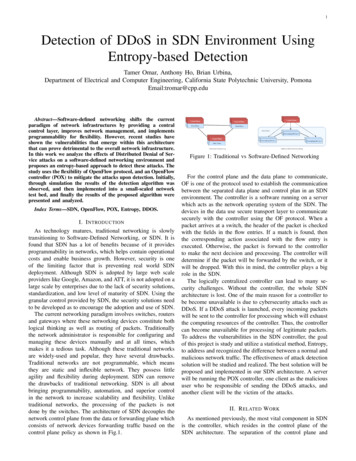
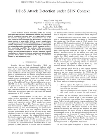
covers the related work. Section III gives an overview of oursystem. We present our sequential and concurrent detectionmethods in Section IV and Section V respectively. We comparethe two methods in Section VI. Section VII introduces theclassification method we used in our detection. Section VIIIpresents our experiment results. The paper is concluded inSection IX.II.R ELATED W ORKCharacteristics of DDoS attacks have been widely studied.Researchers have proposed various methods, e.g., covarianceanalysis, cluster analysis, wavelets, to detect attacks [3], [7],[8], [9], [10]. In network measurement, some papers studiedhow to spread the load of measurement across the wholenetwork [11], [12], [13]. Our DDoS detection work buildson top of the existing SDN proposals [14], [2], [15], [16].There are some work on how to do measurement under SDNenvironment [13], [17], [18], [6], [19]. Among them, [18]discusses the tradeoff between detection accuracy and resourceconsumption. [17] proposes a measurement framework basedon sketch. [19] studies how to detect heavy hitters on a singleswitch. [13] proposes an adaptive flow counting method foranomaly detection. They install rules across the network andadaptively change rule granularity to do anomaly detection.In our method, we also utilize all switches in the wholenetwork. But our methods capture the asymmetry feature ofDDoS attacks to achieve higher detection accuracy. Industryhas also proposed SDN based DDoS attack detection, e.g., theDefense4All solution [20] in OpenDayLight [21]. The basicidea is to collect statistics from some locations in the networkto identify the anomaly traffic. For those suspicious traffic, theywill be diverted to a scrubbing center to do further detectionand flow cleaning. The drawback of this method is that itintroduces additional delay to the traffic, which will degradeuser quality-of-experience (QoE) of delay-sensitive services.[6] also studies how to utilize SDN to do DDoS detection.But they assume that the installed rules could always reachthe finest granularity, which cannot hold in reality due tothe limited TCAM sizes. We use Self Organizing Mapping(SOM) [22] as our DDoS attack detection classifier. Somework discussing how to utilize SOM to do anomaly or intrusiondetection can be found in [23], [24].III.S YSTEM OVERVIEWGenerally, DDoS attack defense consists of two procedures:victim detection and post-detection. We will describe each ofthe procedures in details in the following.The aim of victim detection procedure is to quickly andcorrectly detect DDoS attack victims. As stated in the introduction, the key to correctly identify DDoS attack victimsis to jointly consider the flow volume feature and the flowrate asymmetry feature. To capture these two features, forany potential victim IP we should have measurement rules torecord the total flow rate coming to this IP as well as the totalflow rate going out of this IP . Since TCAM size is limited, wecannot install the above measurement rules for all individualIP addresses in the whole network. Thus, initially we can onlyobserve flow volume and flow rate asymmetry for large IPranges. If our captured features for these large IP ranges showpotential DDoS attacks, we will adaptively zoom in to findthe precise victim IP address. Otherwise, we will adaptivelyzoom out to save TCAM size for detecting other potentialvictim IP ranges. Due to TCAM size limit, we may neverfind the precise IP addresses of victims if TCAM sizes are notlarge enough. The victim detection procedure finishes with thesmallest possible IP ranges containing potential victims.Another procedure is post-detection procedure. There aretwo ways to react to the detected DDoS attacks. One way is todo passive processing, e.g., contacting the user of the victimIP and asking him to migrate his normal service to a new IP.But usually the migration process may take some time and italso wastes resources of the victim server. Another way is todo active processing, e.g., network admins find the attackerIP addresses and install rules in Openflow switches to droppackets from attackers to the victim. Through this way, it savesnetwork resources and doesn’t affect normal operation of thevictim user. Like the victim detection procedure, detection ofattackers is conducted adaptively. This is the post-detectionprocedure we will study in this paper. And we call thisprocedure as attacker detection procedure.The above two procedures could be done either sequentiallyor simultaneously, which results in two different detectionmethods. We will discuss these two different methods in moredetails in the following two sections.IV.S EQUENTIAL M ETHODThe general work flow of the Sequential Method is shownin Figure 1. We start with the initial rule partition/placement,followed by the victim detection. After victims are identified,attacker detection procedure is conducted. We will describethe components in detail in this section.Initial RulePartition &&PlacementVictim DetectionRule AdaptationVictim DetectionAttacker DetectionRule AdaptationAttacker DetectionFig. 1: Work Flow of Sequential DetectionA. Victim Detection1) Initial Rule Placement: Initially, if we don’t have anyprior knowledge about whether a DDoS attack has happenednor what IP ranges contain the victim servers, the DDoSdetection system need to monitor all IPs in the system. Tomake detection fast and accurate, we want to make the IPrange granularity for monitoring as small as possible. Given thelimited flow table sizes on all switches, our design objective isto minimize the maximum granularity among all monitored IPranges. In other words, we don’t want to have a large numberof IP addresses monitored by a single rule. Besides, for eachmonitored IP range, we need to measure the total rate of trafficgoing into all IP addresses in that range, as well as the totalrate of traffic going out from all IP addressed in that range, tocapture the flow rate asymmetry feature.Following the SDN rule definition, each IP range isdefined using the common prefix of all addresses in thatrange. Secondly, given a source IP range Rs and a destination IP range Rt , we want routing paths between all
possible source and destination pairs between the two ranges{ s, t , s Rs , t Rt }, go through the same sequenceof SDN switches in the network. To measure the flow rateasymmetry, we additionally want routing paths in the reversedirection { t, s , t Rt , s Rs } also follow the samesequence of SDN switches. We assume that we are working ona PoP-level topology, and all traffic between two PoP routersgo through the same sequence of SDN switches. Then we caninitialize the coarse IP ranges using the sets of IP addressesbehind all PoP routers. In case the IP set behind a PoP routercannot be exactly summarized using any prefix matching rule,we will further divide the set into subsets until each subsetcan be exactly summarized using a prefix matching rule. Ifthe routing assumption doesn’t hold, we also need to furtherdivide PoP level IP ranges until hosts in between each pairof ranges go through the same sequence of SDN switches.After this operation, we call each pair {Rs , Rt } of source anddestination IP ranges as a flow f .After the initial rule setup, we determine the victim IPrange granularity for measurement and the monitor rule placement for each flow. Generally, there are two ways to do rulemanagement. The first way is to dedicate one measurementrule solely for one potential victim IP range. It means that ifwe want to split victim IP range, we only split the victim IPrange and keep the attacker IP range the same as the initialpartitioned ones generated by rule partition and placementmethod. For example, assuming that two flows A B andB A exist in the network, we can use rules A Band B A to observe the potential victim IP ranges Aand B. If now we want to zoom in both victim IP range Aand victim IP range B, the rule split method will generaterules A1 B, A2 B, B A1 and B A2 solely fordetecting potential victims in IP range A. And rules A B1 ,A B2 , B1 A and B2 A will be generated to solelydetect potential victims in IP range B. The second way of ruleorganization method is that each rule is used to monitor boththe source victim IP range and the destination victim IP range.It means that if source IP range and destination IP range areall suspected as victims, we not only split destination victimIP range but also split source victim IP range for one rule. Forexample, when we decide to split A and B using this method,we will generate A1 B1 , A2 B1 , A1 B2 , A2 B2 ,B1 A1 , B2 A1 , B1 A2 and B2 A2 to monitor IPranges A and B. If we want to further split both A and B intomore ranges to do monitoring, the second way will generatemore monitor rules compared to the first way. In general, if wewant to split both A and B into k ranges to do monitoring, thefirst approach will generate 2k rules to monitor A and 2k rulesto monitor B, a total of 4k rules; while the second approachwill generate 2k 2 rules to simultaneously monitor A and B,which is much larger than the first approach when k 2.In the Sequential Method, we use the first rule organizationmethod as it would generate fewer rules to detect victim. Inour Concurrent Method, we use the second rule organizationmethod, which we will discuss in details later.Employing the first rule organization method, we useAlgorithm 1 to do the initial rule partition and placement. Wefirst set up one rule for each flow f to be monitored. 1 Let Nf1 Keeping in mind, to detect the rate asymmetry, for each IP range pair A, B , we will have two flows to be monitored: A B and B A.be the number of monitor rules associated with flow f . Thus,initially we have Nf 1 and place a single monitor rule for fon some switch on the path from IP range Rs to IP range Rt .Since we are focusing on the victim detection at this stage,we only worry about the granularity of the monitored victimIP range, which we define as its monitor granularity. First, weset the monitor granularity G to be a large value Gupper . Wethen try to reduce G iteratively. In each iteration we find themaximum granularity Gmax among all the monitor IP range.Then, for each rule with the maximum monitor granularityGmax , we divide its monitor IP ranges into two halves, andreplace it with two new monitor rules, one for each half of thevictim IP range as described in the previous paragraph. As aresult, the maximal granularity is reduced to Gmax /2. Afterrule split, it is possible that the monitoring rules for differentmonitor IP ranges are the same. To save TCAM space, wewill delete redundant rules. Then, we can update the numberof monitor rules Nf for each flow. We will check whetherthe monitor rules can be placed to TCAM of all switches inthe network. If there is a feasible placement, we try to doanother iteration to refine the IP range granularity. Otherwise,the minimum maximum granularity is Gmax and monitor ruleplacement is the one found in the previous iteration.Algorithm 1 Initial Rule Partition and :18:19:20:F : set of flows; R : set of monitor rules; Nf : number ofmonitor rules for flow f ;Initialize monitor granularity to be GupperInitialize monitor rules R for flows in F at granularityGupper ; Calculate Nf , f F ;if Placement(N1 , · · · , NF ) is not Feasible thenRaise Errorend ifwhile 1 doGmax maximum victim range granularity of all rulesin RR̂ Rfor all rules r R̂ with victim range granularity GmaxdoPartition victim IP range into two halves;Replace r with two new rules in R̂;end forRemove redundant rules and Update {Nf , f F }based on R̂;if Placement(N1 , · · · , NF ) is not Feasible thenReturn Gmax and the previous rule set R and theassociated allocationBreakend ifR R̂;end while2) Rule Placement Feasibility Check: The key question forAlgorithm 1 is that given switch space requirement {Nf , f F }, how to decide whether the monitor rule placement isfeasible or not. This problem could be transformed to theclassical maximum flow problem and then be solved by theFord-Fulkerson algorithm [25]. In Figure 2, we illustrate thevirtual graph for the rule placement check. Basically, thevirtual graph consists of four types of nodes: start node S,terminate node T , flow nodes {fi , i F } and switch nodes
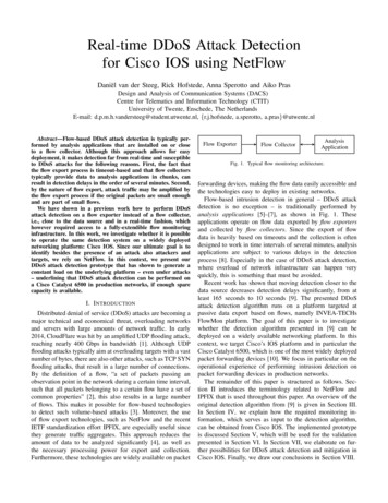
Algorithm 2 Victim Detection Rule Adaptation (D)SN1f1 NfN2 f2 s1 s2fF sSC2C1TCsFig. 2: Virtual Graph for Rule Allocation Check{sj , j S}. Start node S is connected to all flow nodes fi andthe link capacity between S and fi is the required switch spaceNi . Then, flow node fi is connected to all switch nodes sj thatthe flow traverses in the real network. And the capacity forthose links are infinity. At last, a switch node sj is connectedto the terminate node T and the capacity between these two isthe available TCAM rule space capacity Cj on switch sj . Then,after getting this rule allocation network, the original problembecomeswhether the maximum flow between S to T equals to f F Nf . This problem could be solved by utilizing theclassic Ford-Fulkerson algorithm. The idea is that as long asthere is a path from the start node to the terminate node, withavailable capacity on all edges in the path, we will send flowalong one of these paths. We will try to find another path untilno path is available. Then, after the program is terminated, wewill know whether the placement is feasible or not. And if itis feasible, we can also check how many rule space each flowneeds on each switch in the network.3) Detection Rule Adaptation: After the initial rule placement, we will run DDoS attack detection algorithms to estimate the victim likelihood of each IP range in rule set. Forthe IP ranges having no sign of being attacked, we could usecourser-grained rules to replace the finer-grained rules. For theIP ranges with high likelihood of under DDoS attack, we canutilize the available and/or newly released rule space to installfiner-grained rules to monitor them. This adaptation is calledspatial adaptation in [13]. Besides spatial adaptation, we couldalso change the rule fetching period and do temporal adaptationas stated in [13]. In this article, we mainly focus on :15:16:17:18:D : set of victim ranges monitored by rules in R;while 1 dofor d D docollect packet statistics F(d)use victim classifier Cv to calculate Cv (d) to decidewhether d is under attack or not;end forfor d in D doif Cv (d) F alse and Cv (Sib(d)) F alse thenContraction: add monitor rule for victim rangeP arent(d), remove monitor rules for victim rangesd and Sib(d);end ifif Cv (d) T rue and G(d) 32 thenRefinement: add monitor rules for the victim rangesChild(d), remove monitor rule for victim range d;end ifend forif Refined Rule Set Infeasible? thenreturn list of victim ranges with Cv (d) T rueend ifend whileand Sib(d) with monitoring rules for their common parentP arent(d). If C(d) T rue, d is a probable DDoS attackvictim. We will try to refine the observation granularity ford by replacing monitoring rules for d with monitoring rulesfor its two children3 . And if the granularity level is alreadythe finest, we will do attacker detection. Each time we refineobservation granularity, we need to utilize Algorithm 1 todecide whether the adaptation is feasible or not. In the currentadaptation process, for each refinement or contraction process,we only increase or decrease the granularity by one prefix bit.We could also try larger adaptation steps. But if the adaptationstep is too large, we may waste many TCAM sizes for falsepositive alarms.B. Attacker Detection ProcedureAfter locating the potential victim IP ranges, we willstart the attacker detection procedure. The attacker detectionprocedure also works in an adaptive fashion. Details of thealgorithm are listed in Algorithm 3. For each range s, we willuse attacker classifier Cs (s) (see details in Section VII) toidentify whether the attacker is within this ranges s. If yes,we will zoom in range s to explore the IP further. If the rangeis already at the finest level or the switches do not have enoughTCAM space for the refined rule set , we will return the sourceIP or the source IP ranges directly.In Algorithm 2, we illustrate our adaptation algorithmto iteratively locate the potential victim IP ranges. For eachdestination IP range d in the current monitor rule set, wecollect its traffic statistics and use DDoS attack victim classifierCv (see details in Section VII) to calculate one value Cv (d).If Cv (d) F alse, d is not identified as a potential victim.If its sibling Sib(d) is also not a victim2 , we can increasethe observation IP range by replacing monitoring rules for dIn the previous sequential method, only after detecting theexact victim IP ranges, we will start the attacker detection.Another way of DDoS attack detection method is to do victimdetection and attacker detection concurrently. The work flow ofthe Concurrent Method is shown in Figure 3. The basic idea2 A sibling range of a /x range d is the other /x range sharing the same/(x 1) prefix with d.3 The two children of a /x range d is the two IP ranges sharing the same/x prefix with d and the (x 1)-th bit is 0 and 1 respectively.V.C ONCURRENT M ETHOD
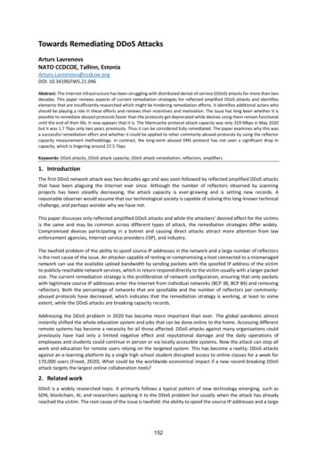
Algorithm 3 Attacker Detection Rule Adaptation :S : set of IP ranges sending traffic to victim IP ranges;while 1 dofor s S docollect packet statistics features F(s)use attacker classifier Cs to calculate Cs (s) to decidewhether s is an attacker or not;end forfor s in S doif Cs (s) T rue thenif G(s) 32 thenReturn selseRefinement: add monitor rules for the attackerranges Child(s), remove monitor rule for attacker range s;end ifend ifend forif Refined Rule Set Infeasible? thenreturn list of attacker ranges with Cs (s) T rueend ifend whileis that if a victim IP range is being suspected under DDoSattack, not only we should refine the measurement granularityfor the victim range, but also we should simultaneously refinethe measurement granularity for all IP ranges that are classifiedas attackers of the victim, so that we can identify the potentialattackers in the mean time. The simultaneous attacker andvictim range refinement procedures are conducted in both theinitial rule placement and the subsequent rule adaptation. Sim-Initial RulePartition && PlacementTABLE I: Rule Split for rule A BFig. 3: Work Flow of Concurrent Detectionilar to the Sequential Method, the first step of the ConcurrentMethod is to do initial IP range separation to form flow f . Thenwe will do the initial rule partition and placement. Differentfrom the Sequential Method, rules are not solely organizedbased on the victim IP ranges, and we use the second ruleorganization method as described in Section IV-A1. Our initialrule partition and placement are the same as in Algorithm 1.We also try to minimize the maximum monitoring granularity.But the rule refinement is different from the sequential method.Due to the simultaneously splitting of source and destinationIP ranges, we will generate more monitoring rules. Therefore,it is expected that the final victim IP ranges obtained in theConcurrent Method will have coarser granularities than thoseobtained in the Sequential Method.After the initial rule partition and placement, we will goto the concurrent rule adaptation process, as described inAlgorithm 4. In the adaptation process, for any modificationdone for monitoring rule of A B, we will also dothe corresponding modification to the monitoring rule of theRule SplitNo SplitSplit both A and BSplit BSplit both A and BTABLE II: Rule Merge for rule A BConditionRule MergeA or B is victimA, B and their siblings are not victimA and its sibling are not victimB and its sibling are not victimNo merge for A, BSource and destination sibling mergeSource sibling mergeDestination sibling mergereverse flow B A to make sure that the new formed flowsare still organized in pair. For rule A B, if at least one of Aand B is identified as potential victim, we will do rule split, asdepicted in Table I. If neither A nor B is a potential victim, wewill try to do rule merge. For one rule t, source sibling mergemeans that we merge source range of t with its sibling rangeand destination sibling merge means that we merge destinationrange of t with its sibling range. Under these definitions, wecould do rule merge as Table II states. The details of ruleadaptation is listed in Algorithm 4. We will use classifier Cvto identify the potential victims, and for each victim d, we useclassifier Csd to identify the suspicious attackers of victim d.After the concurrent adaptation ends, we will find the potentialvictims as well as suspicious attackers attacking those victims.Algorithm 4 Concurrent Rule Adaptation R1:2:3:Victim && AttackerDetection Rule AdaptationVictim && Attacker DetectionConditionNeither A or B is victimA, B are both victimB is victim, A is not attacker for BB is victim, A is attacker for 2:23:24:R : set of current monitor rules;D : set of victim ranges monitored by rules in R;Sd : set of attacker ranges monitored for victim ranges dby rules in R;while 1 dofor d D docollect packet statistics F(d)use victim classifier Cv to calculate Cv (d) to decidewhether d is under attack or not;end forfor sd Sd where Cv (d) T rue docollect packet statistics features F(sd )use source classifier Csd to calculate Csd (sd ) todecide whether s is an attacker for victim d or not;end forfor r R dosd SourceRange(r); dd DestinationRange(r);if Cv (sd ) T rue or Cv (dd ) T rue thenDo rule split according to Table I;elseDo rule merge according to Table II;end ifend forif Splited Rule Set Infeasible? thenreturn list of potential victim ranges with corresponding suspicious attacker rangesend ifend while
VI.C OMPARISON OF T WO M ETHODSIn this section, we discuss the pros and cons of the abovetwo proposed methods. Both methods can identify DDoSattack victims as well as attackers precisely given large enoughTCAMs on all switches. If TCAM sizes on switches areconstrained, both methods can only detect the victims andattackers at coarse IP range granularities.At the initialization stage, both methods will try to makethe IP observation ranges as small as possible. The SequentialMethod can reach finer victim observation IP ranges, since theConcurrent Method use more TCAM space to monitor possibleattacker IP ranges. Thus, if the objective is to quickly identifythe victims, the Sequential Method is more preferable, as itcan find the finest victim IP ranges under the TCAM sizeconstraints. If the objective is to quickly find the victims aswell as the attackers, the choice between the two depends onthe TCAM capacities. If the TCAM capacities are pretty large,Concurrent Method is more preferable, as it can quickly findthe victims along with the attackers. On the other hand, ifthe TCAM capacities are very constrained, it is likely thatthe Concurrent Method will exit at a very coarse observationgranularity, while at least the Sequential Method can pinpointthe victims precisely. Thus, the preferred method under variousconditions can be summarized as in Table III.4)Among the above four features, feature P and B onlyconsider the volume flowing to a potential victim. When DDoSattack happens, values of these two features become very large.Feature PA and feature BA quantify the traffic asymmetry ofDDoS attack. When DDoS attack happens, compared to theincoming flows, flows going out of a victim would be muchsmaller. Thus, we can also observe a large value for these twoasymmetry features.2) Attacker Identification Features: Using the previousnotations, for a potential victim IP range j, the attacker identification features to identify whether IP range i has attackersfor range j could be expressed as follows:1)2)TABLE III: Method Selection under Various ConditionsTCAM Size LimitVictim DetectionAttacker and Victim DetectionSmall SizeMedium sizeLarge sizeSequentialSequentialSequential or ConcurrentSequentialSequential or ConcurrentConcurrent3)4)VII.C LASSIFICATION M ETHODIn the above two DDoS detection methods, we will useclassifiers to detect victims as well as attackers. In this section,we will in
Generally, DDoS attack defense consists of two procedures: victim detection and post-detection. We will describe each of the procedures in details in the following. The aim of victim detection procedure is to quickly and correctly detect DDoS attack victims. As stated in the intro-duction, the key to correctly identify DDoS attack victims