Transcription
Downloaded from orbit.dtu.dk on: Aug 20, 2022Experimental study on strength and ductility of underwater fillet welds in repairingoffshore steel structuresChen, Xiao; Kitane, Yasuo ; Itoh, YoshitoPublication date:2009Document VersionPeer reviewed versionLink back to DTU OrbitCitation (APA):Chen, X., Kitane, Y., & Itoh, Y. (2009). Experimental study on strength and ductility of underwater fillet welds inrepairing offshore steel structures. Paper presented at 3rd International Conference on Advances inExperimental Structural Engineering, San Francisco, United States.General rightsCopyright and moral rights for the publications made accessible in the public portal are retained by the authors and/or other copyrightowners and it is a condition of accessing publications that users recognise and abide by the legal requirements associated with these rights. Users may download and print one copy of any publication from the public portal for the purpose of private study or research. You may not further distribute the material or use it for any profit-making activity or commercial gain You may freely distribute the URL identifying the publication in the public portalIf you believe that this document breaches copyright please contact us providing details, and we will remove access to the work immediatelyand investigate your claim.
EXPERIMENTAL STUDY ON STRENGTH AND DUCTILITY OF UNDERWATERFILLET WELDS IN REPAIRING OFFSHORE STEEL STRUCTURESXiao Chen1, Yasuo Kitane1 and Yoshito Itoh1ABSTRACTUnderwater wet welding is one of the most common repair measures for corroded offshore steelstructures. Few studies have been carried out systematically concerned with mechanicalproperties of such welds, thus current design provisions rely heavily on limited experimental dataon welds made underwater and design properties for corresponding welds made in air. Thispaper presents a series of experiments on forty-five fillet welded specimens featuring weldingboth in air and underwater. Weld strength and ductility of fillet welds are examined throughstrength tests, which are also complemented by Vickers hardness tests and microstructureexamination to better understand the weld details. The tested parameters include two weldingenvironments, two weld orientations, two base structural types, and four base steels. Based onthe tests, differences between underwater and in-air fillet welds are examined in terms ofstrength, ductility, and failure modes, underwater weldability of base steels is also evaluated.INTRODUCTIONMany offshore steel structures, including marine platforms, trestles, pier piles, etc. have beensuffering from increasing corrosion damages. These corroded steel structures are in urgent needof repairing and strengthening to retain or extend their service lives. Among all repair strategiesavailable, underwater wet welding is one of the most common measures due to its highefficiency and relatively low cost (Coastal Development Institute of Technology 1997, Liu2005). This technique has been adopted over years and gained popularity in offshore andmaritime engineering for recent energy explorations into the sea (Wernicke and Billingham1998).However, because of remarkable difference in welding environments, mechanical properties ofwelds produced underwater vary distinctly from those produced in air. Underwater welds havebeen studied a lot during past decades, most studies have focused on their metallurgical features(Kinugawa and Fukushima 1982, Ibarra et al. 1988), influence of quenching (Pope et al. 1996),development of new electrodes suitable for underwater wet welding (West et al. 1990), etc.Although some papers have studied mechanical properties of underwater welds (Akselsen et al.2006, Zhang et al. 2003, Rowe et al. 2002), few studies have been carried out systematically forweld joint design. Due to a deficiency of test data, Japanese provision discounts strength ofunderwater welds by taking 80% of that of in-air welds irrespective of structural types, weldorientations, base steel types, and corrosion effects (Coastal Development Institute ofTechnology 1997). The main motivation of present study is to provide fundamental data on thestrength of underwater fillet welds.In this study, forty-five fillet welded specimens are tested to failure. Weld strength, ductility, andfailure modes are examined with respect to two welding environments: in-air and underwater,1Dept. of Civil Engineering, Nagoya University; Nagoya, Japan1
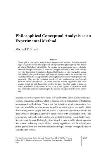
two structural types: steel pipe and steel sheet pile, two weld orientations: transverse andlongitudinal, and four base steels commonly used in offshore structures: SY295, SYW295, andcorroded SY295 for steel sheet piles, and STK400 for steel pipes. SY295, SYW295, andSTK400 are Japanese Industrial Standard (JIS) designations, and they are specified in JISA5528, JIS A5523, and JIS G3444, with defined yield stresses 295 MPa, 295 MPa, and 235 MPa,respectively. Differences in mechanical properties between underwater welds and theircounterpart in-air welds are investigated qualitatively as well as quantitatively. To understandweld features in detail, Vickers hardness tests and microstructure examinations are alsoperformed to corroborate the mechanical features of underwater fillet welds. Based onexperimental results, the paper ends with conclusions on weld strength and ductility in variouscases.EXPERIMENT PROGRAMThe main variables investigated in the fillet weld tests are welding environments, structuraltypes, weld orientations, and base steel types. Table 1 presents the test matrix indicating differentweld assemblies with their designations and parameters.Test Specimens and Material PropertiesTwo configurations of specimens with different weld orientations are illustrated schematically inFig. 1. In order for welds to fail before base or cover steels yield, the weld leg length is specifiedTable 1. Test matrixAssembly DesignationNo. of Structural WeldingWeldSpecimens type environment 5In air3LYA3SY295Longitudinal SYW2954LWA35LCA3CSY295Sheet SY295Longitudinal SYW2959LWW310LCW2CSY29511TSA4TransverseIn derwater14LSW4Longitudinal*Test data for pipe are from Watanabe et al. (2009).2BaseWeldCoverthickness(mm) length(mm) steel12.7 mm40 mm6-8 mm20 mm12.7 mm40 mm6-8 mm20 mm12.7 mm40 mmSM490ASM490B
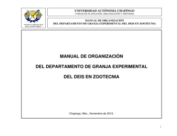
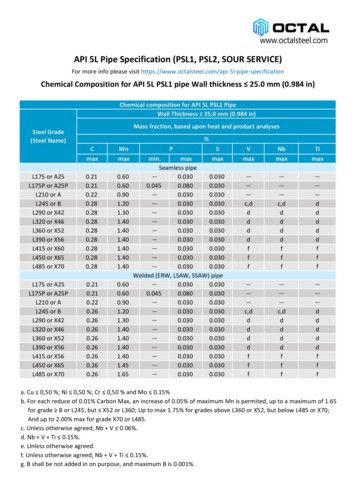
Front elevationFront elevation5l 5l 540 40l 40 or 204075Clip gauge200Side elevation99100200200Clip gauge9t912.7Side elevationt 12.7 or 6-8(b) Longitudinal specimen12.7200(a)Transverse specimenFig. 1. Specimen configurations (in mm)as 6 mm. One weld pass is used in welding process for all welds. Other welding details are listedin Table 2. Mechanical properties of steels, listed together with chemical compositions in Table3, are obtained from static tensile coupon tests. To distinguish corroded and uncorroded SY295steels, corroded SY295 base steels is referred to as CSY295 in this paper. It should be noted thatCSY295 base plates with thickness varying from 6 to 8 mm are cut from in-situ steel sheet piles,which have been exposed to marine environment for about 35 years, to study corrosion effects onweld properties. Before tests, accurate weld profiles are measured by a laser displacement sensor.Table 2. Welding detailsCaseWeldingOrientation Current(A) Voltage(V)environmentLongitudinal 70-80Transverse55-70Sheet pileLongitudinal 80-95UnderwaterTransverse75-95Longitudinal 100-110In airTransverse 90-100PipeLongitudinal 120-140UnderwaterTransverse 120-140In mperature( C )pHSalinity(wt-%)17--147.92.6---25.68.22.1Test SetupThe specimens are tested quasi-statically under monotonic tensile loading using a 500 kN MTSmaterial testing machine. Deformation of individual weld is recorded during the test by clipgauges placed at the ends of welds shown in Fig.1. Fig. 2 illustrates test setup in the experimentprogram. In this study, weld strength is defined asσw Pmaxna l(1)where σ w is the fillet weld strength, Pmax is the maximum load of the specimen, a is the averagethroat thickness of all welds in concerned specimen, l is the average weld length, n is the numberof welds in specimen’s cross section, which is 2 for transverse specimens, 4 for longitudinalspecimens. By adopting n , the formula implicitly assumes the total load is shared equally bywelds in the same cross section of specimen in spite of slight asymmetry in the weld shape. Weldductility, a normalized deformation factor, is defined as3
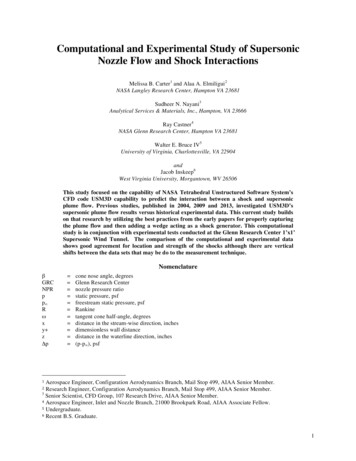
Δl Δfs(2)where Δl is ductility factor, Δ f is fracture deformation of the first fractured weld, and s is weldsize. The definition of weld size is shown in Fig. 3.Table 3. Material properties of steelsMechanical propertiesChemical compositions (wt-%)UltimateMaterial Young's Poisson's Yield stress,Elongation,stress, σ umodulus,σ y (MPa)ratio, vΔA 952130.29273497410.30 0.06 0.72 0.016CSY2952120.29349531340.27 0.02 0.96 0.013SYW2952130.28392513420.10 0.23 1.41 0.020STK4002030.28362394410.12 0.10 0.56 0.013SM490A2090.28361532390.16 0.34 1.44 0.015SM490B2130.28290416460.12 0.23 1.02 0.013Electrode**410460300.10 0.10 0.43 0.015* CEIIW C (Si Mn)/6 (Cr Mo V)/5 (Ni Cu)/15. Only first two terms used except SYW295.**Catalogue value from the manufacturer.wsh sawss haw, h weld leg lengths weld size a weld throatFig. 3. Definition ofweld sizesFig. 2. Test setupEXPERIMENTAL RESULTS AND DISCUSSIONSLoad-Deformation CurvesGenerally, welds on the specimens of the same assembly exhibit similar load-deformationresponses, even for the welds located on either convex or concave side of pipe material STK400.In order to compare results clearly, 14 load-deformation curves of the first failed weld, one ofeach assembly type, are plotted in Fig. 4. Depending on the size of weld throat, stiffness during4
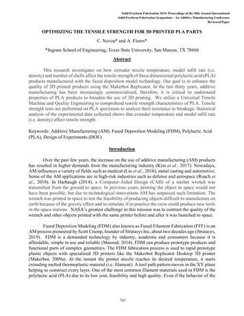
initial elastic phase varies from 1738 to 2761 kN/mm. Most of underwater welds show largerultimate load when compared with their counterpart in-air welds. However, due to thesignificantly smaller weld throat, LSW specimen with an average weld throat 3.7 mm has asmaller ultimate load than LSA specimen with an average weld throat 5.0 mm. Anotherobservation is that all underwater weld specimens show significantly smaller fracturedeformation than their counterpart in-air welds. There are always “plateau” before in-air weldsfail, while for underwater welds, fracture comes soon after their maximum loads.200Applied load (kN)Applied load ATYWTWATWWTSATSW0.511.5Weld deformation (mm)(b) Transverse specimenWeld deformation (mm)(a) Longitudinal specimenFig. 4. Load-deformation curves of weldsStrength and DuctilityTo examine the results quantitatively, weld strength versus ductility factor are plotted in Fig. 5.In general, underwater welds show higher strength but lower ductility than in-air welds althoughsome differences exist among different weld assemblies. Fig. 6 shows strength increase andductility decrease of underwater welds in percent when compared with counterpart in-air welds.Strength increase ranges from 6.9% to 41.0%, while ductility decrease is about 50% except twocases: transverse welds on SY295 and longitudinal welds on CSY295. Moreover, weldorientations affect this strength increase and ductility decrease due to underwater welding tosome degree as observed in Fig. 6. As for welds on SY295, strength increase is nearly doubledfrom 23.7% to 41.0% and ductility decrease is also nearly doubled from 23.8% to 50.3% whenweld orientations change from the transverse to the longitudinal, although those of SYW295 arenot affected. Welds on corroded SY295 exhibit a relatively small strength increase of 21.7% buta drastic ductility decrease of 88.1%. As for absolute values, the LCA welds have the largestductility factor with an average value of 0.61 but their counterpart underwater welds, LCW, havethe smallest ductility factor with an average value of 0.09 among all longitudinal welds.It should also be noted that the strength of longitudinal welds tends to increase with ductilityfactor as shown in Fig. 5(a), and this trend is more pronounced in welds produced underwater. Itis found that weld strength, to some extent, is affected by how much the weld can deform beforeits failure. Regarding nonuniform stress distribution in longitudinal fillet welds, where the shearstress is larger at two ends and smaller in between (Suzuki 1982), smaller ductility will preventadditional load from being shared by weld elements in the central region after weld elements atthe two ends yield. Consequently, the smaller the deformation capacity at weld ends in alongitudinal weld, the smaller weld strength will be. As expected, no positive correlationbetween strength and ductility is found in transverse welds made underwater or in-air as shownin Fig. 5(b), as a result of the uniform distribution of shear stress in the weld beads.5
800600700Weld strength (MPa)Weld strength (MPa)500400300Bond Bond 00Bond failureBONDfailure300DEPO/Bond .800.05Ductility factor0.10.150.20.25Ductility factor(a) Longitudinal specimen(b) Transverse specimen60%40%20%41.0%30.4%23.7%30.3%21.3% 0.6% tility decreaseStrength increaseFig. 5. Weld strength versus ductility factor-54.5% -50.8%Longitudinal-84.5%-100%Fig. 6. Relative change of weld strength and ductility ofunderwater welds when compared with in-air weldsTo examine the effect of corrosion on strength and ductility of fillet welds, welds on corrodedSY295, i.e. CSY295, and those on SY295 are compared. Although the chemical compositions ofCSY295 and SY295 are similar as shown in Table 3, LCW welds with an average strength of435 MPa exhibit smaller strength by 10.8% than LYW welds with an average strength of 482MPa. However, for corresponding in-air welds, LCA welds have slightly larger strength with anaverage strength of 357 MPa than LYA welds with an average strength of 342 MPa. Thisphenomenon can be explained by ductility of those welds. LCW welds show a ductility factor of0.09, while LYW welds show 0.23 which is 2.6 times larger than LCW. As for LCA and LYAwelds, the ductility factors are 0.61 and 0.46, respectively. The smaller ductility of LYA resultsin the smaller strength than LCA welds. The ductility factor of LCW is turned out to be thesmallest among all longitudinal welds, which will be examined in the following sections offailure modes and hardness distribution.6
Failure ModesIn Fig. 5, the failure modes are also indicated. It is observed that specimens failed at weld deposit(DEPO) except for those circled welds which fail either at boundary between weld deposit andbase metal (BOND) or with a combination of DEPO and BOND (DEPO/BOND). Fig. 7 showsrepresentative photos of different failure modes. It is of interest to note that BOND andDEPO/BOND failure modes occurred only in underwater welds. All six underwater fillet weldswith base steel SY295 fail at BOND or DEPO/BOND regardless of the weld orientations, and alltwo underwater fillet welds with base steel CSY295 exhibit brittle fractures at BOND, with littledeformation in weld metals, consequently lower ductility and smaller strength are inevitable inLCW welds. Moreover, with base steels of STK400 and SYW295, underwater fillet welds fail atBOND or DEPO/BOND with frequencies of two out of eight and two out of six respectively.Considering the differences in carbon contents of base steels as shown in Table 3, the findings infailure modes suggest that “milder” steels STK400 and SYW295 with lower carbon equivalentsof 0.230 and 0.379, respectively, have better weldability in underwater environments than“tougher” steels SY295 and CSY295 with higher carbon equivalents of 0.430 and 0.433,respectively.TYA1#1LWA2#4(a) DEPO failureTWW2#1LYW1#1(b) DEPO/BOND failureTYW3#1LCW3#8(c) BOND failureFig. 7. Comparison in failure modesHardness and MicrostructuresWelding is a thermo-mechanical process, and weld properties are closely related to thermalconditions which dominate weld microstructures and in turn affect mechanical properties. Thissection discusses results from Vickers hardness tests and metallographic examinations of filletwelds. The specimens for hardness tests are produced simultaneously with specimens for weldstrength tests to ensure the same welding conditions.7
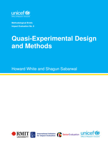
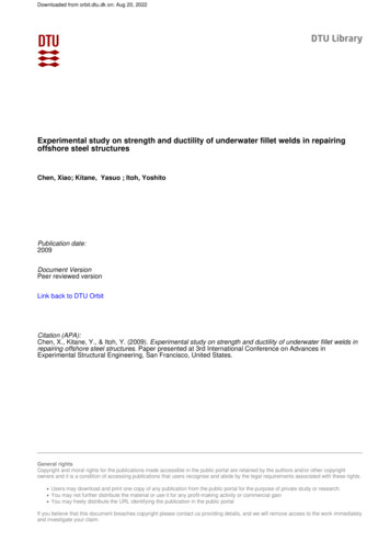
ase plate-5-4200300400500LCW-baseHv Max: 522100HAZBase plate200300400500LCA-baseHv Max: 213-3HAZ21DEPO-7 -6 -5 -4 -3 -2 -1 0100Cover plateDEPO1HAZ400300-6 -5 -4 -3 -2 -1 0Cover plate500LCW-coverHv Max: 421500LCA-coverHv Max: 239Fig. 8. Hardness distribution of weldsFig. 8 shows photos of polished and etched cross sections of LCA and LCW specimens withVickers hardness results superimposed. Points for hardness data acquisition are located along thearrows. Two small windows in white at boundaries of weld deposit and heat affected zone(HAZ) signify the areas where microstructure images shown in Fig. 9 are taken. These photosare representative to reveal general features of fillet welds examined in this study, although thereare some differences in the magnitude of hardness and detailed microstructures among differentweld assemblies. As shown in Fig. 8, hardness peaks can be found in the coarse grained regionof HAZ in both in-air and underwater welds. Due to the rapid quenching, heat transfer is limitedin a smaller region resulting a HAZ size of 1 to 2 mm and HAZ hardness of 310 to 526 Hv forunderwater welds whereas they are 3 to 4 mm and 198 to 375 Hv for in-air welds.(II)Underbead cracks(III) 20 um(I) 100 um(III) 20 um(I) 100 um(a) LCA(II)(b) LCWFig. 9. Weld microstructures at the boundary of DEPO and HAZMoreover, there are similar tendencies of microstructure distributions within welds made in thesame environment despite of differences in base steels. Microstructures of LCA and LCW weldsat BOND areas are illustrated in Fig. 8a(I) and 8b(I). The microstructures of DEPO are shown inFig. 8a(II) and 8b(II), DEPO in LCA is mainly composed of ferrite and pearlite with 150 Hv andDEPO in LCW is composed of ferrite-pearlite jointly with 170 Hv. The microstructures at HAZin LCA, as shown in Fig. 8a(III), are composed of ferrite and pearlite with 200 Hv, while themicrostructures at HAZ in LCW, as shown in Fig. 8b(III), are dominated by martensite with 500Hv. In addition, there are underbead cracks found in the boundary areas between DEPO and8
HAZ only in, but not all underwater welds. Underbead cracks are observed in the boundary areasin TYW, LYW welds, and more in LCW welds, these welds are on SY295 and CSY295 steels.Whereas no crack is observed in TWW, LWW, TSW and LSW welds on SYW295 and STK400steels, although some of them exhibit BOND failures. This further corroborates that SY295steels do not have good weldability in the underwater wet environment although they are quitesound in the open air environment compared with SYW295 and STK400 steels. The distinctmechanical mismatching and many underbead cracks in the boundary areas between DEPO andHAZ are responsible for the significantly low ductility of LCW welds.CONCLUSIONSUnderwater fillet welds were studied experimentally with respect to strength and ductility.Fourteen fillet weld assemblies, 45 specimens in total, were tested to failure. Mechanicalproperties of underwater welds were examined when compared with their counterpart in-airwelds. Main conclusions obtained in this study are summarized below.1. Underwater fillet welds have larger strength but smaller ductility when compared with in-airwelds. Strength increase of underwater welds when compared with their counterpart in-air weldsranges from 6.9% to 41.0% depending on weld assemblies, while ductility decrease is nearly thesame at 50%.2. When the weld orientation changes from the transverse to the longitudinal direction, thestrength increase is nearly doubled from 23.7% to 41.0% on SY295 steels, tripled from 6.9% to21.3% on STK400 steels and unchanged at around 30% on SYW295 steels. Underwaterlongitudinal welds exhibit a pronounced positive correlation between weld strength and ductilityfactor.3. Underwater fillet welds on corroded SY295 steels show a strength increase of 21.7% and adrastic ductility decrease of 84.5% when compared with those on original SY295 steels. Thisinferior ductility is found to be caused by mechanical mismatching and underbead cracks in theboundary areas between DEPO and HAZ.4. The weldability of STK400 and SYW295 steels is good in both in-air welding and underwaterwelding, while the weldability of SY295 steels, although it is quite sound in in-air welding, isundesirable in underwater welding.ACKNOWLEDGMENTSThis research was partially supported by The Japan Iron and Steel Federation and NagoyaUniversity. The authors would like to acknowledge their support.REFERENCESAkselsen, O. M., Fostervoll, H., Harsvaer, A., Aune, R. 2006. Weld metal mechanical propertiesin hyperbaric GTAW of X70 pipeline. International Journal of Offshore and PolarEngineering 16(3):233-240.Coastal Development of Institute of Technology. 1997. Port Steel Structure CorrosionPrevention and Repair Manual. Coastal Development Institute of Technology, Japan (inJapanese).Ibarra, S., Grubbs, C. E., and Olson, D.L. 1988. Metallurgical aspects of underwater welding.Journal of Metals 40(12):8-10.9
Kinugawa, J., and Fukushima, S. 1982. Influence of equivalent carbon contents of steels onproportions of martensite, hardness and susceptibility to cold cracking at coarse-grainedregions in underwater wet welding. Welding Society Journal 51(3):45-51 (in Japanese).Liu, S. 2005. Maintenance and repair welding in the open sea. Welding Journal 84(11):54-59.Pope, A., Teixeira, J., Dos Santos, V., Paes, M., and Liu, S. 1996. The effect of nickel on themechanical properties of high-oxygen underwater wet welds. Journal of Offshore Mechanicsand Arctic EngineeringTransactions of the ASME 118(2):165-168.Rowe, M. D., Liu, S., and Reynolds, T. J. 2002. The effect of Ferro-Alloy additions and depth onthe quality of underwater wet welds. Welding Journal 81(8):156S-166S.Suzuki, H. 1982. Recent Welding Engineering. Corona Publishing Co., Ltd. Tokyo, Japan (inJapanese).Watanabe, N., Kitane, Y., and Itoh, Y. 2009. Modeling of joint behavior of steel pipes repairedwith steel plate by underwater wet welding. Journal of Structural Engineering, JSCE55A(3):903-914 (in Japanese).Wernicke, R., and Billingham, J. 1998. Underwater wet repair welding and strength testing onpipe-patch joints. Journal of Offshore Mechanics and Arctic Engineering, ASME 120(4):237242.West, T. C., Mitchell, G., and Lindberg, E. 1990. Wet welding electrode evaluation for shiprepair. Welding Journal 69(8):46-56.Zhang, X. D., Chen, W. Z., Ashida, E., Matsuda, F. 2003. Metallurgical and mechanicalproperties of underwater laser welds of stainless steel. Journal of Material Science &Technology 19(5):479-483.10
The tested parameters include two welding environments, two weld orientations, two base structural types, and four base steels. Based on the tests, differences between underwater and in-air fillet welds are examined in terms of strength, ductility, and failure modes, underwater weldability of base steels is also evaluated. INTRODUCTION