Transcription
IP Camera User ManualO8FB7M /O8FD4MO6FB7M /O6FD4MPlease read this manual carefully before operating the unit and keep it for further reference.
IP Camera User ManualImportant Safeguards and WarningsWelcomeThank you for purchasing this network camera!This owner’s manual is designed to be a reference tool for your system.Please read this manual carefully before operating the unit and retain it for future reference.Should you require any technical assistance, contact Speco Technologies Tech Support at 1-800-645-5516Important Safeguards and Warnings1.Electrical safetyAll installation and operation here should conform to local electrical safety codes.Use a certified/listed 12VDC Class 2 power supply only.Please note: Do not connect two power supplying sources to the device at the same time; it may result in devicedamage! The product must be grounded to reduce the risk of electric shock.Improper handling and/or installation could run the risk of fire or electrical shock.2.EnvironmentHeavy stress, violent vibration or exposure to water is not allowed during transportation, storage and installation.This product should be installed in a cool, dry place away from direct sunlight and heat sources.Do not install the product in extreme temperature conditions.Do not expose the camera to electromagnetic radiation. Otherwise it may result in CMOS sensor failure.Do not block any ventilation openings.Do not allow water and liquid intrusion into the camera.3. Operation and Daily MaintenancePlease shut down the device and then unplug the power cable before you begin any maintenance work.Do not touch the CMOS sensor optic component. You can use a blower to clean the dust on the lens surface.Always use the dry soft cloth to clean the device. If there is too much dust, use a cloth dampened with a small quantity ofneutral detergent. Finally use the dry cloth to clean the device.Please use a professional optical cleaning method to clean the enclosure. Improper enclosure cleaning (such as using cloth)may result in poor IR functionality and/or IR reflection.The grounding holes of the product are recommended to be grounded to further enhance the reliability of the camera.Dome cover is an optical device, please don’t touch or wipe cover surface directly during installation and use, please refer tothe following methods if dirt is found:Stained with dirt: Use oil-free soft brush or hair dryer to remove it gently.Stained with grease or fingerprint: Use oil-free cotton cloth or paper soaked with alcohol or detergent to wipe from the lenscenter outward. Change the cloth and wipe several times if it is not clean enough.2
IP Camera User ManualWarningThis camera should be installed by qualified personnel only.All the examination and repair work should be done by qualified personnel.Any unauthorized changes or modifications could void the warranty.StatementThis guide is for reference only.Product, manuals and specifications may be modified without prior notice. Speco Technologies reserves the right to modifythese without notice and without incurring any obligation.Speco Technologies is not liable for any loss caused by improper operation.Note:Before installation, check the package and make sure that all components are included.Contact your rep or Speco customer service department immediately if something is broken or missing in the package.Accessory NameAmountNetwork Camera Unit1Junction Box1Quick Start Guide1Installation Accessories Bag1CD13
IP Camera User ManualTable of ContentsRegulatory ----------------------------21.Introduction . 6Welcome . 62.Web Access and Login . 72.1 LAN . 73.Live View . 84.Camera Configuration . 94.1 System. 94.1.1 System Restart . 94.1.2 Factory Default . 104.1.3 Export / Import . 104.1.4 Date / Time . 114.1.5 System Log. 114.1.6 SD Card . 124.1.7 System Information. 124.2 Basic Setup . 134.2.1 Video Setup . 134.2.2 Audio Setup . 144.2.3 Image Setup . 144.2.4 Display . 164.3 Network Setup . 174.3.1 IP Address Setup. 174.3.2 DNS . 174.3.3 DDNS Client . 174.3.4 NTP . 184.3.5 FTP . 184.3.6 SMTP . 194.3.7 RTSP . 194.3.8 SNMP . 204.3.9 Port Setting . 204.3.10 IP Filter . 214.3.11 UPnP . 214.4 Event Setup . 224
4.4.1 Motion Detection. 224.4.2 Tampering Alarm . 224.4.3 Alarm In Mode . 234.4.4 Notification . 234.3.5 SD Recording . 244.5 User Admin . 254.5.1 Password Change . 254.5.2 User Account . 25Appendix . 26Appendix 1 Troubleshooting . 265
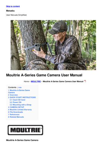
IP Camera User Manual1. IntroductionThank you for purchasing this network camera!Please read this manual carefully before operating the unit and retain it for future reference.Should you require any technical assistance, please contact Speco Technologies Technical Support.Applications6
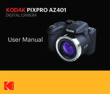
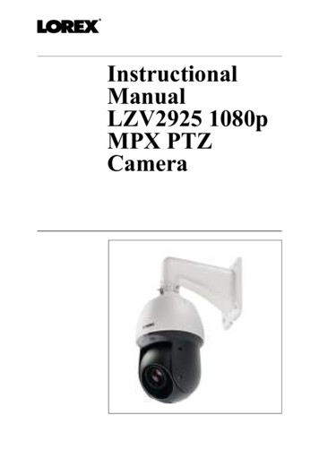
IP Camera User Manual2. Web Access and LoginThe IP camera settings can be accessed via a web browser through the LAN.2.1 LAN Access through IP ScannerNetwork connection:① Make sure that the camera and the PC are connected on the same local network. The camera is set to DHCP by default and will be assignedan IP address by the DHCP server.Make sure that the local network has a DHCP server. Routers typically have a DHCP server built in.② Install IP Scanner from the CD and run it after installation. IP Scanner is the tool for discovering the IP cameras on the local network.③ In the device list, the IP address, model number, and MAC address of each device will be listed. Select the applicable device and doubleclick to open up the web viewer. You can also manually enter the IP address in the address bar of the web browser.When prompted, enter the user name and password of the device. Default user name is admin and password is 1234. After logging in, followdirections to install applicable plug-ins for viewing video.7
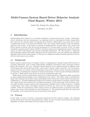
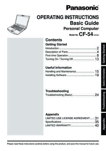
IP Camera User Manual3. Live ViewThe window below will be shown after logging in.The following table describes the buttons on the live view interface.FunctionButtonDescriptionStreamDropdown menuChoose which stream to viewVideo SizeFixedScales the video to fit in the browser windowVideo SizeOriginalShows the video in the original resolutionRecord VideoStartStarts manual recording of video to PC.Files are saved as AVI. Once started, the device willrecord continuously until stopped.Record VideoStopStops recording of videoZoomZoom Zoom in control for models with motorized lensZoomZoom -Zoom out control for models with motorized lensFocusFocus / Focus -Manual focus adjustment controlAudioMicEnables microphone input for live view on browserAudioSpeakerEnables speaker output on camera for live view onbrowser8
IP Camera User Manual4. Camera ConfigurationPress the “Setup” button to go to the configuration interface.Note: Wherever applicable, press the “Save” button to save the settings.4.1 System4.1.1 System RestartThe device can be restarted here.4.1.2 Factory DefaultIf the device needs to be factory reset for any reason, it can be done here. Be aware that this procedure will erase all settings that were changedand saved in the device and restore them to a factory default state. If restoring settings after a factory reset is desired, makesure to back up the settings using the “Export” function before the factory reset procedure.9
IP Camera User Manual4.1.3 Export / ImportExportClick the button to download the current system settings as a configuration file on the local PC.ImportUpdates the device with settings that were saved with the Export function. This is useful after a factory reset.Browse to the directory where the configuration file was saved, select it, and click “Upload File”.10
IP Camera User Manual4.1.4 Date / TimeTime ZoneSelect the appropriate time zone of the location of the device. The system time will update automatically if the device is connected to the internet.Setup TimeIf the device is not updating the time automatically for some reason, the time can be adjusted manually. Click the checkbox and change the timeaccordingly.4.1.5 System LogSystem log provides information on actions that were performed on the device such as providing the IP address of a PC that logged in to thedevice along with the date and time. Select the desired category to view and specify the start and end times to display the logs. Then click on“Search Logs” to retrieve the logs.11
IP Camera User Manual4.1.6 SD CardApplies only to models with micro SD card slot. This page displays the total capacity and the remaining capacity for the micro SD card that’scurrently in use on the device. If a card is inserted while the device is powered on, the device may need to be restarted in order for the micro SDcard to be recognized. Click on Format to format the card for use on the device. SD Card List shows the dates and the times of recordings that arestored on the card. Playback can be done through SecureGuard VMS.4.1.7 System InformationSystem InformationProvides information such as the current firmware version of the device and the model number. The device nickname can also be set up here.HTTP API Authentication and WSSE Authentication are used for 3rd party integration purposes and can remain disabled unless specificallyneeded.12
IP Camera User ManualNetwork InformationProvides network information of the device such as IP address and Mac address.4.2 Basic SetupBasic Setup includes setup for video, audio, and image settings.4.2.1 Video SetupResolution, frame rate, etc. can be adjusted in this section. Each setting can be adjusted per stream. There are 3 streams in total – one mainstream and two sub streams.Codec: For the main stream and sub stream 1, this is set to H.264. For sub stream 2, there is an option to choose betweenH.264 and MJPEG.Resolution: Set the desired resolution for each stream from the drop down list.Frame Rate: Set the desired frame rate for each stream from the drop down list. Range is from 1 fps to 30 fps.G.O.P: Stands for “Group of Pictures”. This determines how many frames are processed in between unique I-frames. For example, if the framerate is set to 30 fps and the GOP value is set to 1, there would be 30 I-frames per second. I-frames contain much more data compared to Pframes or B-frames. The higher the GOP value, the higher the image quality will be. For decoding process considerations, GOP should be set to avalue equal to or greater than the frame rate.Bitrate Mode: Choose between CBR (constant) or VBR (variable). The bitrate used in video encoding has a direct impact on the video quality andthe bandwidth used to stream video over the network. As opposed to constant bit rate (CBR), VBR files vary the amount of output data per timesegment.VBR allows a higher bit rate (and therefore more storage space) to be allocated to the more complex segments of media files while lessspace is allocated to less complex segments. The bits available are used more flexibly to encode t he video data more accurately, with fewer bitsused in less complex scenes and more bits used in complex scenes. CBR is the best option if the available bandwidth must be limited.Bitrate: Sets the target bitrate. The acceptable minimum bitrate is around 1 Mbps per megapixel. So a 1080p resolution (2MP)should be set to 2Mbps at a minimum.Profile: Select between Baseline, Main, or High profiles for H.264.Corridor View: This changes the camera view from a landscape view to a portrait view. This mode is useful for looking down a narrowhallway for example.13
IP Camera User Manual4.2.2 Audio SetupFor models with audio capability, audio input and output can be enabled / disabled here as well as volume adjustment.4.2.3 Image SetupImage settings such as brightness, contrast, white balance, etc can be set up here. Image settings (where available):- 8MP(O8FB7M /O8FD4M)IP Camera User Manual14
Brightness: Adjusts the brightness of the image. If set too high, it can have a white-out effect on the image.Contrast: Adjusts the contrast of the image which is the difference between black and white (color differentiation). If set too high, bright scenesmay look too bright.Sharpness: Enhances edges for a sharper image perception. The higher the value, the less “soft” the image looks. However, if set too high, thismay introduce artifacts in the video.Saturation: Increasing the saturation increases the color level. The value 255 gives maximum color saturation. The value 0 gives a black andwhite image.Exposure: Set the amount of light which reaches your camera sensor.D to N: Sets the threshold at which the image switches from color to monochrome. The higher the value, the more the camera tries to stay in coloras ambient light level is reduced.N to D: Sets the threshold at which the image switches from monochrome to color.FIT: FIT stands for Flexible Intensifier Technology. Using Speco’s low-light technology called Intensifier, the camera stays in color even in lowlight, to produce a quality color image. As light level drops even further, the camera will adjust itself automatically to provide the mode that willproduce the best image according to the scene. The available modes are: color, monochrome without IR, and monochrome with IR.Day/Night: Can be set to Auto, Color, or Monochrome. If FIT mode is on, then this mode will be set to auto.Presets: Presets adjust the WDR and Intensifier values automatically based the mode that’s chosen. WDR and Intensifier can also beadjusted manually.WDR: WDR(Wide Dynamic Range) enables a user to view the area more clearly even under backlight environment. Real WDR.ATR: ATR(Adaptive Tone Reproduction) improves the contrast of images that contain both very bright and very dark areas, producing greatervisible detail in each extreme. Digital WDR.3DNR: Cuts off the noise of video. A 3D filter improves on the results of a 2D filter by eliminating motion blur, as well as image noise.White Balance: It adjusts color settings to achieve consistent quality in the white areas and other colors of the image.V-Flip: Turn the current video image vertically.Intensifier: As light level gets reduced, the Intensifier value can be increased to try to retain a color image.Frequency: NTSC / PALShutter Speed: Adjust it according to the lightening conditions. Shutter speed is the value of the sensor exposure time.- 6MP(O6FB7M /O6FD4M)IP Camera User Manual15
4.2.4 DisplayDisplayEnables an on-screen display on the video stream.Position: Static places the OSD on a predefined area in the image. Variable allows for a user-specified location.Size: Size of the font in the OSD.Content Input: User-specified text. This can be used to display the nickname of the device.Date/Time DisplayEnables an on-screen display of the date/time on the video stream.Position: Static places the OSD on a predefined area in the image. Variable allows for a user-specified location.Size: Size of the font in the OSD.IP Camera User Manual4.3 Network Setup4.3.1 IP Address Setup16
Sets the IP address, subnet mask, and gateway of the local network that the device is connected to. If the local network supports DHCP, thedevice can be set to DHCP mode and the network will assign an IP address to the device. The device is set to DHCP mode by default.4.3.2 DNSThe DNS server addresses can be set up here. This does not have to be set up when using DHCP.4.3.3 DDNS ClientThe device can be connected to Speco’s DDNS server so that it can have a host name.IP Camera User ManualClick “Enable” to enable DDNS mode.Enter a hostname for the device. The default name that’s provided has the last 6 digits of the Mac address as part of the name.If the name is found to be unique, it will be registered successfully on the DDNS server.17
4.3.4 NTPThe device can configure the date and time automatically via an NTP (network time protocol) server if it is connected to the internet.The host name is “pool.ntp.org” by default. Other NTP servers can be entered manually. The Date / Time section under System Setup usesthis NTP server to update the time when the time zone is selected.4.3.5 FTPAn FTP server can be used to store images for events. Enter the FTP server address, user ID, account password, and the port of theFTP server. Then enter the file name prefix and the file storage location on the server. For the file name, the date and time will beappended to the prefix.IP Camera User Manual4.3.6 SMTP18
Emails can be sent with images when events occur. For the SMTP server setting, enter the information of the outgoing mail server.For common email services such as Gmail or Yahoo Mail, please check the SMTP settings for those services first and then enter them here.For SMTP Account Setting, enter the sender’s email address and up to 5 emails addresses for the receiver.4.3.7 RTSPRTSP stands for Real Time Streaming Protocol and is used by various clients to stream the video from the device. Examples of clients areSpeco’s NVRs and SecureGuard VMS. Other than changing the RTSP port (default is 554), the other options are advanced and donot need to be changed from the default settings for most applications.IP Camera User Manual4.3.8 SNMP19
To get camera status, parameters and alarm information and remotely manage the camera, the SNMP function can be used.Before using SNMP, please install an SNMP management tool and set the parameters of SNMP, such as SNMP port, trap address.1. Go to the SNMP section.2. Select the corresponding version (SNMPv1/SNMPv2c or SNMPv3) according to the version of the SNMP software that will be used.3. Set the values for “Read SNMP Community”, “Write SNMP Community”, “Trap Address”, “Trap Port” and so on. Please makesure the settings are the same as that of the SNMP software.4.3.9 Port SettingSet up the ports that are used to access different camera functions.IP Camera User Manual4.3.10 IP Filter20
IP filtering can be used to provide access or deny access to a specific set of IP addresses.1. Select Enable and the select either “All Accept” or “All Drop”.2. If All Drops is selected, then nobody can access the device except for a specified list of IP addresses and vice versa for All Accept.3. Specify the range of IP addresses under “Rule” and click Add to add the IP addresses to the list.4. Up to 100 IP addresses can be listed.4.3.11 UPnPIf this function is enabled, the device will attempt to automatically open up ports on the local network and can be quickly accessed on thelocal network.The UPnP friendly name can be entered.IP Camera User Manual4.4 Event Setup4.4.1 Motion Detection21
Motion detection zone and sensitivity can be set up in this section.1. Set the sensitivity of motion detection for the zone. Higher sensitivity means that motion alarms will be triggered more easily.2. Click and drag the desired zone in the window. The defined zone will be highlighted.4.4.2 Tampering AlarmThe device can detect tampering such as a global scene change and out of focus.IP Camera User Manual4.4.3 Alarm in ModeFor devices with a sensor input, choose between Normally open or Normally closed.22
4.4.4 NotificationThis section is used to control how notifications are delivered for motion and tampering alarm events.Email: Choose the event type. Interval time defines how often the email is sent out. Images of the event can be attached to theemail if enabled.FTP: Choose the event type. Interval time defines how often the alarm image is uploaded to FTP.IP Camera User ManualAlarm Out: For devices with a relay output, events can be triggered to set off the relay device.23
4.4.5 SD RecordingSD card recording can be set up to record in various scenarios. Network failure – records to the SD card when the network connection fails Schedule – can be set up for continuous or events. Continuous recording on a schedule is not recommended to be used all the time.SD cards use flash memory which have a limited lifespan, so continuous recording will shorten the lifespan quickly.Pre Alarm Size is the pre-record time. Post Alarm Time is the post-record time.IP Camera User Manual24
4.5 User Admin4.5.1 Password ChangeChange the password of the admin account.4.5.2 User AccountAdd or modify user accounts here.Enter the user ID of the account to be created or modified and enter the new password. To delete an account, click on the accountto be deleted and click “Delete”.25
AppendixAppendix 1 TroubleshootingIP Scanner does not show any device.Make sure that the PC that’s running IP Scanner is on the same local network as the devices.Internet Explorer cannot download ActiveX controlIE browser may be set up to block ActiveX. Follow the steps below.1. Open IE browser and then click Tools Internet Options2. Select Security and then Custom Level.3. Enable all the options under “ActiveX controls and plug-ins”.4. Click OK to finish setup.No sound can be heard.1. Audio input device is not connected. Please connect and try again.2. Audio function is not enabled at the corresponding channel. Please enable this function.26
① Make sure that the camera and the PC are connected on the same local network. The camera is set to DHCP by default and will be assigned an IP address by the DHCP server. Make sure that the local network has a DHCP server. Routers typically have a DHCP server built in. ② Install IP Scanner from the CD and run it after installation.