Transcription
Waukee Flo-MeterInstallation, OperationAnd Maintenance Manual – revision 3
Waukee Flo-Meter – Rev 3Page 2Manual #: 001Rev No: 3Date: 25 March 2013COPYRIGHTNo part of this publication may be reproduced, transmitted, transcribed, stored in a retrieval system,or translated into any language or computer language, in any form or by any means, electronic,mechanical, magnetic, optical, chemical, manual, or otherwise, without prior written permission ofUnited Process Controls Inc.DISCLAIMER:The Waukee Flo-Meter is to be used by the industrial operator under his/her direction. WaukeeEngineering is not responsible or liable for any product, process, damage or injury incurred whileusing the Waukee Flo-Meter. United Process Controls Inc. makes no representations or warrantieswith respect to the contents hereof and specifically disclaim any implied warranties or merchantabilityor fitness for any particular purpose.For assistance please contact:United Process Controls Inc.TEL: 1-414-462-8200 FAX: 1-414-462-7022Toll free North America: p-upc.comCopyright 2013, United Process Controls Inc.All rights to copy, reproduce and transmit are reserved
Waukee Flo-Meter – Rev 3Page 3TABLE OF CONTENTS1.INTRODUCTION .42.FLO-METER OVERVIEW .53.SPECIFICATIONS.64.INSTALLATION .74.1M Series Flo-Meter Preparation. 74.2L Series Flo-Meter Preparation . 74.3S Series Flo-Meter Preparation . 84.4Piping the Flo-Meter . 84.5Recommended Piping . 94.6Solenoid Valve Use . 104.7External Flow Control. 104.8Flo-Meter Final Assembly. 105.CALIBRATION AND MAINTENANCE . 115.1Points to Check When Servicing the Flo-Meter . 116.FLO-METER MANUAL CONTROL VALVES . 127.FLO-METER INLET CONDITIONS . 137.2Gas Flo-Meter Correction Factor . 137.3Liquid Flo-Meter Correction Factor . 168.TROUBLESHOOTING . 169.APPENDIX “A” - DRAWINGS. 1810.Waukee Warranty Policy, Disclaimer and Limitation of Liability . 19Copyright 2013, United Process Controls Inc.All rights to copy, reproduce and transmit are reserved
Waukee Flo-Meter – Rev 31.Page 4INTRODUCTIONThe Purpose of this ManualThank you for purchasing a Waukee Flo-Meter. This manual shows you how to install andmaintain Waukee Flo-Meter. This manual contains important information and should be readand understood by all individuals who install, use or service this equipment.Technical SupportWe strive to make our manuals the best in the industry. We rely on your feedback to let usknow if we are reaching our goal. If you cannot find the solution to your particular application,or, if for any reason you need technical assistance, please call us at: 1-414-462-8200 Toll free North America: 1-800-438-3347Our technical support group will work with you to answer your questions. They are availableMonday through Friday from 8:00 A.M. to 4:30 P.M. Central Standard Time. We alsoencourage you to visit our web site where you can find technical and non-technical informationabout our products and company.www.group-upc.comIf you have a comment, question or suggestion about any of our products, services, ormanuals, please e-mail or contact us by phone.Conventions UsedWhen you see the “exclamation point” icon in the left-hand margin, the paragraphto its immediate right will be a warning. This information could prevent injury, lossof property, or even death in extreme cases. Any warning in this manual shouldbe regarded as critical information that should be read in its entirety. The wordWARNING or CAUTION in boldface will mark the beginning of the text.CAUTIONCopyright 2013, United Process Controls Inc.All rights to copy, reproduce and transmit are reserved
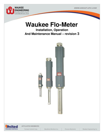
Waukee Flo-Meter – Rev 32.Page 5FLO-METER OVERVIEWThe Waukee Flo-Meter is a precision instrument for the indication of rates of flow of air, liquid andindustrial gases. Each Flo-Meter is calibrated to the specific specifications of the application asspecified when ordered. Meet NFPA requirements for “Visual indication of flow”. Available in a widerange of sizes for almost any gas or liquid, with capacities from 5CFH (.14CMH) to 40,000CFH(1,132CMH)* for gases and 1.5GPH (5.7LPH) to 20GPH (75LPH)*for liquids. Flo-Meters can bepanel mounted, and are designed to be trouble free and easily maintained.*Capacities are based on standard conditions.WARNING: Flo-Meters that are equipped with a Valve are not designed for positiveshut-off. Valves may leak gas into equipment and cause asphyxiation or poisoningto personnel within confined space. If positive shut-off is desired install amechanical valve prior to the Flo-Meter and verify that it is shut-off prior toservicing equipment attached to the unit.CAUTIONCopyright 2013, United Process Controls Inc.All rights to copy, reproduce and transmit are reserved
Waukee Flo-Meter – Rev 33.Page 6SPECIFICATIONSWaukee Flo-Meters are available in many different configurations some of the configurations are: Add a Standard or Precision manual control valve for manual flow control Add a Waukee-Tronic Flow Sensor to send a 4-20mA signal to a Field Device to log the flow Add a Electronic Control Valve (Ex. Valve-Tronic-Plus, SAV-Plus, or Ratio-Prover) forautomatic flow control Add a Flo-Alarm to trigger a high or low flow alarm. If you require a set flow rate, add an orifice valve. (Ex. Purge Nitrogen)Waukee Flo-Meters are designed to operate at a specific temperature, pressure and with a specificgas type. In order to maintain accuracy, the Flo-Meter must be used for the conditions it wascalibrated for.Accuracy: 3.5% of Reading between 25 and 90% of Full ScaleMax Pressure:Gas Flo-Meter Materials:S1 thru S7 - 100psi (689kPa)SF1 thru SF7 – 100psi (689kPa)M1 thru M11 – 50psi (344kPa)L1 thru L6 – 50psi (344kPa)L7 thru L10 – 50psi (344kPa)MPX1 thru MPX11 – 100psi (689kPa)LPX1 thru LPX6 – 100psi (689kPa)LPX7 thru LPX10 – 50psi (344kPa)Flo-Meter Components – AluminumCalibration weights – Lead /SSStandard Seals – Buna-NHigh Temp Seals - SiliconInlet/Outlet Connections:Liquid Flo-Meter Materials:S1 thru S7 – ¼” MNPTSF1 thru SF7 – ¼” MNPTM1 thru M7 – ¾” FNPTM8 thru M11 – 1¼ ”FNPTL1 thru L3 – 1¼” FNPTL4 thru L6 – 2”FNPTL7 – 3”FNPTL8 & L9 – 4” FNPTL10 – 5” FNPTFlo-Meter Components – BrassCalibration weights – Brass/SSStandard Seals – EPWARNING: Exceeding the maximum pressure rating may cause the sight glass tubeto shatter. Use of a pressure relief valve is required by NFPA guidelines andrecommended by Waukee. Failure to advise to this warning may result in damage tothe Flo-Meter as well as personal injury.CAUTIONCopyright 2013, United Process Controls Inc.All rights to copy, reproduce and transmit are reserved
Waukee Flo-Meter – Rev 34.Page 7INSTALLATIONThe Flo-Meter is shipped as a complete unit. Before installation of the Flo-Meter, inspect it for anysigns of shipping damage. Then check the Flo-Meter “Data Plate”, “Scale” and “Gas Tab” to ensureit was built to your specifications.4.1M Series Flo-Meter PreparationBefore installation of the Flo-Meter carefully remove the GuardAssembly, to achieve this, lay the Flo-Meter on its back on a workspace. Then hold the Guard Assembly with one hand, whileunscrewing the Union Nut counterclockwise with the other hand toloosen it. Refer to Figure 1CAUTION: Once the Guard Assembly is loose fromthe Flo-Meter make sure to carefully pull the GuardAssembly from the Flo-Meter straight back off theFloat Rod Assembly. Moving the Guard Assemblyto one side or another during removal may resultin damage to the Float Rod Assembly. Inaccuratereadings my result if the Float Rod is bent.CAUTIONOnce the Guard Assembly is removed from the Flo-Meter,remove the Float Rod Assembly by grasping onto the Float StopBody and carefully pulling it straight back out of the Flo-Meter.Verify that the serial number stamped on the Float Rod Assemblymatches the serial number on the Flo-Meter. Then store it in asafe location until the Flo-Meter Body is mounted.4.2L Series Flo-Meter PreparationBefore installation of the Flo-Meter carefully remove the GuardAssembly, to achieve this, lay the Flo-Meter on its back on a workspace. Screw the Hoke Screw clockwise into the Flo-Meter tohold the Float Rod Assembly in place. Then hold the GuardAssembly with one hand, while unscrewing the Union Nutcounterclockwise with the other hand to loosen it. Refer to Figure2.CAUTION: Once the guard assembly is loose fromthe Flo-Meter make sure to carefully pull the GuardAssembly from the Flo-Meter straight back off theFloat Rod Assembly. Moving the Guard Assemblyto one side or another during removal may resultin damage to the Float Rod Assembly. Inaccuratereadings my result if the Float Rod is bent.CAUTIONCopyright 2013, United Process Controls Inc.Figure 1All rights to copy, reproduce and transmit are reserved
Waukee Flo-Meter – Rev 3Page 8Once the Guard Assembly is removed from the Flo-Meter,remove the Float Rod Assembly by grasping onto theFloat Stop Body, then loosen the “Hoke Screw” until theFloat Rod Assembly is loose. Carefully pull the Float RodAssembly straight back out of the Flo-Meter. Verify thatthe serial number stamped on the Float Rod Assemblymatches the serial number on the Flo-Meter. Then store itin a safe location until the Flo-Meter body is mounted.4.3S Series Flo-Meter PreparationBefore installation of the Flo-Meter carefully remove theGuard Assembly, to achieve this, lay the Flo-Meter on itsside on a work space. Then hold the Guard Assemblywith one hand, while unscrewing the Union Nutcounterclockwise with the other hand to loosen it. Refer toFigure 3.CAUTION: Once the Guard Assembly isloose from the Flo-Meter make sure tocarefully pull the Guard Assembly andFloat Rod Assembly from the Flo-Meterstraight back off the Flo-Meter. Moving theGuard Assembly to one side or anotherduring removal may result in damage to theFloat Rod Assembly. Inaccurate readingsmy result if the float rod is bent.CAUTIONOnce the Guard Assembly and Float Rod Assembly areremoved from the Flo-Meter, verify that the serial numberstamped on the Float Rod Assembly matches the serialnumber on the Flo-Meter. Then store it in a safe locationuntil the Flo-Meter Body is mounted.4.4Piping the Flo-MeterWhen piping the Flo-Meter the inlet is at the lower endand the outlet is at the upper end. Use threadingcompound sparingly as any excess may enter the FloMeter and affect its performance. It is important that theFlo-Meter Body be piped absolutely vertical, as deviationmay cause errors in flow indication. If possible, install apressure tap at the inlet of the Flo-Meter for easyverification of correct inlet pressure. See Figure 4 forrecommended piping.WARNING: Flo-Meter must be earthgrounded. Ungrounded Flo-Metersmay become a source of ignition.CAUTIONCopyright 2013, United Process Controls Inc.Figure 2All rights to copy, reproduce and transmit are reserved
Waukee Flo-Meter – Rev 3Page 94.5Recommended PipingWaukee recommends piping the Flo-Meter as shown below inFigure 4. The first regulator is only required if the supplypressure from the tank is higher than 100psi. The nextregulator should be located prior to the inlet of the Flo-Meterand set to the pressure the Flo-Meter is calibrated for. Apressure relief valve should be installed in-between the finalregulator and Flo-Meter and set to a pressure of 20% or lessthan the maximum rated pressure of the Flo-Meter. Thepressure relief valve protects the Flo-Meter in the event of overpressurization and is required per NFPA guidelines. Manuallockable ball valves should be located at the inlet and outlet ofthe Flo-Meter. The ball valves serve two purposes. Theyprovide positive shut-off for service of equipment that the FloMeter is connected to, and also provides a shut-off for easyreplacement of the Flo-Meter if ever required. The unions onthe Inlet and Outlet of the Flo-Meter are not required, butprovide an easy and convenient way to swap the Flo-Meter outwith another Flo-Meter if needed.CAUTION: If the supply fluid is a high pressuresupply, greater than 100 psi (689kPa). It isextremely important to use two pressureregulators. The first regulator should step thepressure down to about double of the finalpressure to the Flo-Meter and the final regulatorshould be set to the calibration pressure of theFlo-Meter. This will protect the Flo-Meter fromhigh pressure fluid in the event that a regulatorwas to fail.OUTLETOUTLETINLETINLETCAUTIONAIRFigure 3Figure 4Copyright 2013, United Process Controls Inc.All rights to copy, reproduce and transmit are reserved
Waukee Flo-Meter – Rev 3Page 104.6Solenoid Valve UseIf your application requires the use of a solenoid valve for flow control it is recommendedto only use Float Rod Assemblies designed to absorb the shock from the pressure spikecaused by solenoid valves. When ordering a Flo-Meter for use with a solenoid valve,make sure to order it with a “Buffer Spring” The buffer spring absorbs the shock due tospiking caused by solenoid valves and prologs the life of the Float Rod Assembly. Figure5 shows a Float Rod Assembly with a buffer spring.4.7External Flow ControlIf your application requires the use of an external flow control valve(Ex. Butterfly Valve, Orifice) it should be located on the outlet of theFlo-Meter. Installing the valve prior to the Flo-Meter will result ininaccuracies in the Flo-Meter readings.4.8Flo-Meter Final AssemblyOnce the Flo-Meter is mounted, remove the red tape from the FloatRod. Insert the Float Rod Assembly into the Flo-Meter by pullingthe float upwards about 3” holding it in this position by grasping thefloat rod and the bottom of the “Float Stop Body” simultaneously asshown in Figure 6 for M & L Series and Figure 7 for S series.Carefully guide the float rod into the bore of the Flo-Meter. Beforereleasing your grasp of the float rod assembly, ensure that the it isheld in place with either the retaining spring (M series Flo-Meters)or with the Hoke Screw (L series Flo-Meters) or with GuardAssembly (S series) Remove the Sight Glass Tube from the GuardAssembly and fill the tube with Waukee Flo-Meter Oil so that thelevel of oil is approximately one (1) inch from the top. Note: Donot put oil in the Sight Glass Tube of meters used for oxygen orliquid service. Oxygen Flo-Meters should be run dry, or withdistilled water. Flo-Meters for liquid service will automatically fill thesight glass tube with liquid when in service. Place the Sight GlassTube back into the Guard Assembly, making sure the Sight GlassTube O-ring is properly seated, and then carefully install the GuardAssembly on to the Flo-Meter.BUFFERSPRINGFigure 5Figure 6 FLOATRODFLOATSTOPUNIONNUTWARNING: Do not fill the Sight Glass Tube withGUARDFlo-Meter oil on meters used for Oxygen service.ASSEMBUse of oil may cause fire or explosion. Serious personal injuryLYmay result from fire or explosion.CAUTIONWARNING: Be sure clear polycarbonate Safety Shield is always inplace when Flo-Meter is in operation. The Safety Shield providesprotection in the event that the Sight Glass Tube was to rupture.Severe injury may result to personnel if Safety Shield is not inplace.CAUTIONCopyright 2013, United Process Controls Inc.Figure 7All rights to copy, reproduce and transmit are reserved
Waukee Flo-Meter – Rev 35.Page 11CALIBRATION AND MAINTENANCEWaukee Flo-Meters are calibrated in our ISO/IEC 17025:2005 accredited laboratory and aretraceable to NIST (National Institute of Standards and Technology). Waukee recommends havingthe Flo-Meters calibrated annually. The Flo-Meters can be either sent back to the factory for recalibration or a field service technician can visit your facilities and calibrate the Flo-Meters in the field.For additional information regarding our calibration services, please contact Waukee.Waukee Flo-Meters are designed for fast and easy maintenance. Maintenance intervals aredepended on the cleanliness of the gas and the application. For example a Flo-Meter used forEndothermic gas service will require more maintenance intervals then a Flo-Meter for Nitrogenservice. It is recommended that you setup a maintenance program within your organization for whento service each Flo-Meter in your facility. The Flo-Meter’s performance will degrade if it is notproperly maintained and will result in inaccurate flow readings.5.1Points to Check When Servicing the Flo-MeterThe following will require removal of the Float Rod Assembly, for removal and installation of the FloatRod Assembly refer to the “Installation” section of this manual. Also refer to the “Installation” sectionfor location of components. Ensure Supply gas is turned off before performing any service work onany Flo-Meters.1. Are the Pressure, Temperature and Specific Gravity (Gas Type) being used the same as whatthe Flo-Meter is calibrated for? This information can be found on the Serial Plate located onthe front of the Flo-Meter. (See Figure 8) Pressure is very critical to the accuracy of the FloMeter, for every 1psi (6.9kPa) from calibrated pressure will result in about a 3% inaccuracy inreading. The temperature will also have a slight effect on the accuracy of the Flo-Meter, forevery 10 of deviation from the calibrated temperature will result in about a 1% inaccuracy.Using a different gas type then what the Flo-Meter was calibrated for may result in hugeinaccuracies, depending on what theFlo-Meter is calibrated for and whatFLO-METERCALIBRATESERIALgas type is currently flowing throughDNUM.the Flo-Meter. If any of these valuesTEMPERATCALIBRATEUREDFLO-METERdeviate from what the Flo-Meter isPRESSUREMODELcalibrated for, you can use aSPECIFICcorrection factor to find out the actualGRAVITYflow rate for a given indicated flowFigure 8rate. Use the Correction factorformula located in this manual.2. Does the serial number on the Flo-Meter match the number stamped on the Float Stop Body?Each Flo-Meter is matched with a Float Rod Assembly. No two Flo-Meters are the same, evenif both Flo-Meters are calibrated for the same specifications. The serial numbers must matchin order for accurate flow measurement.Copyright 2013, United Process Controls Inc.All rights to copy, reproduce and transmit are reserved
Waukee Flo-Meter – Rev 3Page 123. Is the Bore of the Flo-Meter Clean? If not, use a mild detergent or degreaser and nylon borebrush and carefully clean the bore of the Flo-Meter. Dirt and foreign material inside the FloMeter may cause poor performance and inaccuracies in flow readings.4. Is the Float Rod Assembly Clean? If not, use a mild detergent or degreaser and a rag andcarefully clean the Float Rod Assembly. Be very careful not to bend the Float Rod whencleaning the Float Rod Assembly. Bending the Float Rod will result in poor performance andinaccurate readings.5. Are the Calibration Weights securely fastened to the top of the Float Rod and are they flat withrespect to the top of the float? If not this could be the sign of the Flo-Meter being “Spiked”,and a new Float Rod Assembly should be ordered. If the Flo-Meter is being controlled by asolenoid valve resulting in “spiking” the Flo-Meter to full flow, make sure to order yourreplacement Float Rod Assembly with a “Buffer Spring”. The buffer spring will absorb the“Shock” due to spiking and prolong the life of the Float Rod Assembly.6. Is the Float Rod straight? Rotate the float rod to determine if it is straight, bent Float Rodsmay result in undesirable operation and inaccuracies in flow reading. If the Float Rod is bent itis recommended to replace it with a new one.7. Is Float Rod Stop Tube straight and perpendicular with Float Stop Body? If not, order areplacement Float Rod Assembly. Bent Float Rod Stop Tubes may cause poor performanceand inaccurate readings.8. Is the Flo-Meter mounted plumb? If not, re-pipe the Flo-Meter to make it plumb. If the FloMeter is not plumb, it could result in inaccuracies in flow measurement.9. Are Seals and Gaskets in good condition? Inspect all seals and gaskets for cracks, tears,brittleness or abrasions. Order a gasket kit and replace all seals if any are bad.10. Inspect Sight Glass Tube for any cracks or chips and replace if any are found.11. Is Flo-Meter Oil Dirty? If so, replace with new Waukee Flo-Meter oil. Use Only Waukee FloMeter Oil, other oils may result in inaccuracies in the Flo-Meter readings.6.FLO-METER MANUAL CONTROL VALVESWaukee Flo-Meters are available with two types of manual control valves. Precision ManualControl Valves (Needle and Orifice) and Standard Manual Control Valves (Nylon Cone Nose)Precision valves provide precise control for liquids and gases and are designed to be used for aspecific flow rate, while Standard Valves are not flow rate specific and are a more course flowcontrol valve. The Valves are designed to be robust and require little maintenance.Copyright 2013, United Process Controls Inc.All rights to copy, reproduce and transmit are reserved
Waukee Flo-Meter – Rev 37.Page 13FLO-METER INLET CONDITIONSWaukee Flo-Meters are calibrated for use with a specific gas, temperature and pressure, deviationfrom any of the Flo-Meters calibrated parameters will result in inaccuracies in flow readings. If youneed to use the Flo-Meter with different inlet conditions, it is recommended to either send the FloMeter back to Waukee to re-calibrate the Flo-Meter to the new inlet conditions or purchases a newFlo-Meter for the new inlet conditions. Note: Depending on how much the inlet conditions arechanged, the Flo-Meter may not be recalibrated due to the Flo-Meter may not have the capacity toflow at the new inlet conditions and will require a new Flo-Meter. Before changing any Flo-Meterusage, be sure to consult with Waukee. Provide the serial number of the Flo-Meter you intent tochange the inlet conditions along with what you are changing. Waukee will need this information toverify the propriety of your intended usage and the resultant calculations if you intend to use the FloMeter for any conditions other than those specified on the serial plate (Gas Type, Pressure, andTemperature).CAUTION: Serious hazards can result by changing the usage. The Sight Glass Tubemay break or leak at higher pressures and temperatures or internal componentsmay corrode from the gas being used.CAUTIONFlo-Meters for gas are not greatly affected by changes in temperature, but changes in gas type andespecially pressure changes will greatly affect the accuracy of the Flo-Meter. Waukee has provideda correction factor for these changes. Refer to Gas Flo-Meter Correction Factor below.Flo-Meters for liquids are not affected by pressure changes, but are affected by liquid type andespecially temperature. Temperature changes the viscosity of the liquid and in turn affects thereading of the Flo-Meter. Refer to “Liquid Flo-Meter Correction Factor”.7.2Gas Flo-Meter Correction FactorTermsSG1 Specific Gravity of gas the Flo-Meter is calibrated forSG2 Specific Gravity of the gas to be used in the Flo-MeterT1 Absolute Temperature of gas the Flo-Meter is calibrated forT2 Absolute Temperature of gas to be used in the Flo-MeterP1 Absolute Pressure of gas the Flo-Meter is calibrated forP2 Absolute Pressure of gas to be used in the Flo-MeterSF Scale FactorSR Scale Flow ReadingAF Actual Flow RateCopyright 2013, United Process Controls Inc.Conversion of Temperature to AbsoluteAbsolute Temperature 460 NameplateTemperatureOrConversion of Pressure to AbsoluteAbsolute Pressure 14.7 Nameplate Pressurein psiOrAbsolute Pressure 101.4 Nameplate Pressurein kPaAll rights to copy, reproduce and transmit are reserved
Waukee Flo-Meter – Rev 3Example 1The supply pressure to the Flo-Meter is 5psig and the Flo-Meter is calibrated for 1psig and indicates a flow of 200 CFH.1. Start by converting the Pressuresto AbsoluteP2 5 14.7 19.7P1 1 14.7 15.72. Use the following valves tocalculate the Scale Factor (SF)19.715.7 1.123. Multiply the scale reading of theFlo-Meter by the Scale Factor (SF)200 X 1.12 224224 CFH is the actual flow,flowing thru the Flo-Meter at thenew pressure.Copyright 2013, United Process Controls Inc.Page 14Example 2The supply pressure to the Flo-Meter is34.5 kPa and the Flo-Meter is calibratedfor 6.9 kPa and indicates a flow of 200CFH.1. Start by converting the Pressures toAbsoluteP2 34.5 101.4 135.9P1 6.9 101.4 108.32. Use the following valves tocalculate the Scale Factor (SF)135.9108.3 1.123. Multiply the scale reading of theFlo-Meter by the Scale Factor (SF)200 X 1.12 224224 CFH is the actual flow, flowingthru the Flo-Meter at the newpressure.All rights to copy, reproduce and transmit are reserved
Waukee Flo-Meter – Rev 3Page 15Example 3The supply gas temperature is 90 F andthe Flo-Meter is calibrated for 70 F andindicates a flow of 200 CFH.Example 4The supply gas temperature is 90 F andthe Flo-Meter is calibrated for 70 F andindicates a flow of 200 CFH.1. Start by converting the Pressuresto AbsoluteT2 460 90 550T1 460 70 5301. Start by converting the Pressuresto AbsoluteT2 273 32 305T1 273 21 2942. Use the following valves tocalculate the Scale Factor (SF)2. Use the following valves tocalculate the Scale Factor (SF)530550 .983. Multiply the scale reading of theFlo-Meter by the Scale Factor (SF)200 X .98 196196 CFH is the actual flow,flowing thru the Flo-Meter at thenew Temperature.Copyright 2013, United Process Controls Inc.294305 .983. Multiply the scale reading of theFlo-Meter by the Scale Factor (SF)200 X .98 196196 CFH is the actual flow,flowing thru the Flo-Meter at thenew Temperature.All rights to copy, reproduce and transmit are reserved
Waukee Flo-Meter – Rev 37.3Page 16Liquid Flo-Meter Correction FactorFormula:SF VCNVSM x SR AFTermsSF Scale FactorVC Viscosity of Liquid at Flo-Meter calibrated temperatureNV Viscosity of Liquid at new temperatureSR Scale Flow ReadingAF Actual Flow RateTable 1 to the right shows the viscosity of Methanol at differenttemperatures. If the liquid you are using is not Methanol you willneed to look-up the viscosity of the liquid you are using for thespecific temperature as required by the above formulaExample1The supply methanol temperature is 90 Fand the Flo-Meter is calibrated for 70 Fand indicates a flow of 1 GPH.1. Start by looking at Table 1 to findthe viscosities of MethanolVC .5803NV .5062TemperatureViscosity(Centipoises)20 F (-6.7 C)0.947225 F (-3.9 C)0.894830 F (-1.1 C)0.842435 F (1.7 C)0.799540 F (4.4 C)0.763045 F (7.2 C)0.726650 F (10.0 C)0.690155 F (12.8 C)0.663860 F (15.6 C)0.637665 F (18.3 C)0.611470 F (21.1 C)0.587375 F (23.9 C)0.566480 F (26.7 C)0.545585 F (29.4 C)0.524690 F (32.2 C)0.5062Table 12. Use the following valves tocalculate the Scale Factor (SF).5803.5062 1.1463. Multiply the scale reading of theFlo-Meter by the Scale Factor (SF)1 X 1.146 1.1461.146 GPH is the actual flow,flowing thru the Flo-Meter at thenew Temperature.Copyright
Waukee Flo-Meters are designed to operate at a specific temperature, pressure and with a specific gas type. In order to maintain accuracy, the Flo-Meter must be used for the conditions it was calibrated for. Accuracy: 3.5% of Reading between 25 and 90% of Full Scale