Transcription
Installation InstructionsBuilt-In RefrigeratorPart No. 107010 Rev. A/W1037913542 and 48 Inch Models:EF42DBSS, EF42NBSS, EF48DBSS, EF48NBSSIF42DBOL, IF42NBOL, IF48DBOL, IF48NBOL
Table of ContentsRefrigerator Safety.1Model Identification.2Installation Requirements.3-12Tools and Parts. 3Location Requirements.3-4Electrical Requirements.4Water Supply Requirements. 5Tipping Radius.5Product Dimensions.6Door Swing Dimensions. 7Door Panels and Cabinetry Clearance.8-9Custom Panels and Handles. 10-11Custom Side Panels.12-13Installation Instructions.14-21Unpack Refrigerator.14Reduce Tipping Radius. 14.Move Refrigerator into House.14Install Anti-Tip Boards. 15.Connect Water Supply.15-16Plug in Refrigerator. 16Move to Final Location. 16Level and Align Refrigerator. 17Custom Panel and Handle Installation .18Adjust Doors.19Install Side Panel(s). 20Install Base Grille. 20Complete Installation.21Water System Preparation. 21Notes.22Français.23-44Customer Service InformationIf you have questions or problems with installation, contact yourDacor dealer or the Dacor Customer Service Team. For repairsto Dacor appliances under warranty call the Dacor DistinctiveService line. Whenever you call, have the model and serialnumber of the appliance ready. These numbers are found on alabel located on the inside wall of the refrigerator compartment.Dacor Customer ServicePhone: (800) 793-0093 (U.S.A. and Canada)Monday — Friday 6:00 a.m. to 5:00 p.m. Pacific TimeWeb site: www.Dacor.comDacor Distinctive Service (repairs under warranty only)Phone: (877) 337-3226 (U.S.A. and Canada)Monday — Friday 6:00 a.m. to 4:00 p.m. Pacific TimeAll specifications subject to change without notice.Dacor assumes no liability for changes to specifications. 2008 Dacor, all rights reserved.
Refrigerator SafetyYour safety and the safety of others are very important.We have provided many important safety messages in this manual and on your appliance. Always read and obey all safetymessages.This is the safety alert symbol.This symbol alerts you to potential hazards that can kill or hurt you and others.All safety messages will follow the safety alert symbol and either the word “DANGER” or “WARNING.”These words mean:DANGERWARNINGYou can be killed or seriously injured if you don't immediatelyfollow instructions.You can be killed or seriously injured if you don't followinstructions.All safety messages will tell you what the potential hazard is, tell you how to reduce the chance of injury, and tell you what canhappen if the instructions are not followed.IMPORTANT SAFETY INSTRUCTIONSWARNING: To reduce the risk of fire, electric shock, or injury when using your refrigerator, follow these basic precautions: Plug into a grounded 3 prong outlet.Do not remove ground prong. Do not use an adapter. Do not use an extension cord. Disconnect power before servicing. Replace all parts and panels before operating. Remove doors from your old refrigerator. Use nonflammable cleaner.Keep flammable materials and vapors, such as gasoline,away from refrigerator.Use two or more people to move and install refrigerator.Disconnect power before installing ice maker (on ice makerkit ready models only).Use a sturdy glass when dispensing ice (on some models).SAVE THESE INSTRUCTIONSWARNINGProper Disposal of Your RefrigeratorWARNINGSuffocation HazardRemove doors from your old refrigerator.Tip Over HazardRefrigerator is top heavy and tips easily when notcompletely installed.Keep doors taped closed until refrigerator iscompletely installed.Use two or more people to move and installrefrigerator.Failure to do so can result in death or serious injury.Failure to do so can result in death or brain damage.IMPORTANT: Child entrapment and suffocation are not problemsof the past. Junked or abandonedrefrigerators are still dangerous,even if they sit out for “just a fewdays.” If you are getting rid of yourold refrigerator, please follow theinstructions below to help preventaccidents.Before you throw away your oldrefrigerator or freezer: Take off the doors. Leave the shelves in place sochildren may not easily climbinside.1
Model IdentificationRefrigerators With Ice and Water DispensersEF42DBSS and EF48DBSS:42” and 48” dispensing models with all stainless steel finishIF42DBOL and IF48DBOL:42” and 48” dispensing models designed for installation of custompanels and handlesRefrigerators Without Ice and Water DispensersEF42NBSS and EF48NBSS:42” and 48” non-dispensing modelswith all stainless steel finish2IF42NBOL and IF48NBOL:42” and 48” non- dispensing models designed for installation ofcustom panels and handles
Installation RequirementsTools and PartsLocation RequirementsTools needed:Your Dacor refrigerator can be recessed in an opening betweencabinets or installed at the end of a cabinet run using a side panelto enclose the refrigerator.Gather the required tools and parts before starting installation.Read and follow the instructions provided with any tools listedhere.WARNING Cordless drill Drill bits Two adjustable wrenches Phillips screwdriver Small levelExplosion Hazard Appliance dolly Torx †T27 screwdriver ¹¹ 32” nut driver ³ 8” and ¹ 2” open-end wrenches Hex key (5 32”) ¹ 4” and 5/16” socket drivers Tape measureKeep flammable materials and vapors, such asgasoline, away from refrigerator.Failure to do so can result in death, explosion, or fire.IMPORTANT: Observe all governing codes and ordinances.Parts Needed: It is recommended that you do not install the refrigerator nearan oven, radiator, or other heat source. Six #8 x 3” (7.6 cm) wood screws (longer screws may beneeded) Do not install in a location where the temperature will fallbelow 55 F (13 C). One or two 2” x 4” x 32” (5.1 cm x 10.2 cm x 81.3 cm) woodboard(s) Floor must support the refrigerator weight, more than 600 lbs(272 kg), door panels and contents of the refrigerator. Minimum 7 ft (2.1 m) flexible codes approved water supplyline. Ceiling height must allow for side tipping radius. See TippingRadius. EF series models: Dacor handle kit. Location should permit doors to open fully. See Door SwingDimensions. IF series models: Consult a qualified cabinetmaker orcarpenter to make the panels. See Installation Requirementsfor more information. Location must permit top grille removal. See OpeningDimensions.Opening Dimensions To avoid tipping during use, the solid soffit must be within 1”(2.5 cm) maximum above the refrigerator. If the solid soffitis higher than 1” (2.5 cm) or one is not available, then therefrigerator must be braced.If the anti-tip boards are needed, they must be attached to therear wall studs 80” to 90” (203.2 cm to 228.6 cm) above thefloor. See Install Anti-Tip Boards for more information.NOTE: A clearance of ¹ 2” (1.3 cm) must be maintained abovethe top grille in order for the top grille to be removed.1/2” (1.3 cm)† Torx is a registered trademark of Saturn Fasteners Inc.3
Installation RequirementsLocation Requirements (continued) Electrical Requirements Locate the refrigerator so that it may easily be pulled out fromthe wall if service becomes necessary. A grounded 3 prong electrical outlet should be placed asshown in the illustration below. See Electrical Requirementsfor more information. The water shutoff should be located in the base cabinet oneither side of the refrigerator or some other easily accessiblearea. If the water shutoff valve is not in the cabinets, theplumbing for the water line can come through the floor orthe back wall. See Water Supply Requirements for moreinformation.WARNINGElectrical Shock HazardPlug into a grounded 3 prong outlet.Do not remove ground prong.Do not use an adapter.Do not use an extension cord.Failure to follow these instructions can result in death,fire, or electrical shock.BBDimensionBefore you move your refrigerator into its final location, it isimportant to make sure you have the proper electrical connection.Recommended Grounding Method83¹/21/2”(212.1cm)" (212.1cm) min.83cm) max.844" (215.384³/3/4”(215.3cm)to bottom of solid soffitA 115 Volt, 60 Hz., AC only 15 or 20 Amp. fused, groundedelectrical supply is required. It is recommended that a separatecircuit serving only your refrigerator be provided. Use an outletthat cannot be turned off by a switch. Do not use an extensioncord.min.to bottom of solid soffitIMPORTANT: If this product is connected to a GFCI (ground faultcircuit interrupter) equipped outlet, nuisance tripping of the powersupply may occur, resulting in loss of cooling. Food quality andflavor may be affected. If nuisance tripping has occurred, and ifthe condition of the food appears poor, dispose of it.77"77”(195.6 cm)(195.6cm)AA(see chart following)(seechart following)NOTE: Before performing any type of installation, cleaning, orremoving a light bulb, remove the top grille and turn the masterpower switch to OFF or disconnect power at the circuit breakerbox.When you are finished, turn ON the main power switch orreconnect power at the circuit breaker box. Then reset the controlto the desired setting.24”24"(61.0 cm)(61.0cm)Min.min.See page 5Model SeriesCutout Width ADimension BEF42, IF4241½” (105.4 cm) to41¾” (106.0 cm)10”(25.4 cm)EF48, IF4847½” (120.7 cm) to47¾” (121.3 cm)16”(40.6 cm)NOTE: Flooring under refrigerator must be at same level as theroom. The face of the cabinetry must be plumb.4
Installation RequirementsWater Supply RequirementsIf the water pressure to the reverse osmosis system is less than40 to 60 psi (276 to 414 kPa): All installations must meet local plumbing code requirements. Check to see whether the sediment filter in the reverseosmosis system is blocked. Replace the filter if necessary. The water shutoff should be located in the base cabinet oneither side of the refrigerator or some other easily accessiblearea. The right-hand side is recommended.NOTE: If the water shut off valve is in the back wall behind therefrigerator, it must be at an angle so that the water line is notkinked when the refrigerator is pushed into its final position. Allow the storage tank on the reverse osmosis system to refillafter heavy usage. If your refrigerator has a water filter cartridge, it may furtherreduce the water pressure when used in conjunction with areverse osmosis system. Remove the water filter cartridge.If you have questions about your water pressure, call a licensed,qualified plumber.1” x 1”(2.5 cm x 2.5 cm)Tipping RadiusBe sure there is adequate ceiling height to stand the refrigeratorupright when it is moved into place.Possible waterline locations The dolly wheel height must be added to the tipping radiuswhen a dolly is used. If needed, the tipping radius can be reduced. See ReduceTipping Radius.6”(15.2 cm)1”(2.5 cm)6”(15.2 cm) If the water shutoff valve is not in the cabinets, the plumbingfor the water line can come through the floor. A ½” (1.3 cm)hole for plumbing should be drilled at least 6” (15.2 cm) fromthe right or left hand side cabinet or panel. On the floor, thehole should be no more than 1” (2.5 cm) away from the backwall. See Connect Water Supply.Side Tipping RadiusThe side tipping radius varies depending upon the width of themodel. Use the chart provided to determine the side tippingradius.NOTE: Tip on side only. Your refrigerator dealer has a kit available with a ¼” (6.4 mm)saddle-type shutoff valve. Before purchasing, make sure asaddle-type valve complies with your local plumbing codes. Do not use a piercing-type or ³ 16” (4.8 mm) saddle valve whichreduces water flow and clogs more easily. Install the water supply line only in areas where the householdtemperatures will remain above freezing.Water PressureA cold water supply with water pressure between 30 and 120 psi(207 and 827 kPa) is required to operate the water dispenser andice maker. If you have questions about your water pressure, call alicensed, qualified plumber.AModel SeriesTipping Radius AReverse Osmosis Water SupplyEF42, IF4293” (236.2 cm)IMPORTANT: The pressure of the water supply coming out ofa reverse osmosis system going to the water inlet valve of therefrigerator needs to be between 30 and 120 psi (207 and 827kPa). If a reverse osmosis water filtration system is connectedto your cold water supply, the water pressure to the reverseosmosis system needs to be a minimum of 40 to 60 psi (276 to414 kPa).EF48, IF4896” (243.8 cm)5
Installation RequirementsProduct DimensionsSide View:Front View: The depth from the front of the top grille to the back of therefrigerator cabinet is 25 ³ 8” (64.5 cm). Width dimensions were measured from trim edge to trim edge. The power cord is 84” (213.3 cm) long. The water line attached to the back of the refrigerator is 5 ft(1.5 m) long. Height dimensions are shown with leveling legs extended ¹ 8”(3.2 mm) below the rollers. Height dimensions are shown with leveling legs extended ¹ 8”(3.2 mm) below the rollers.25 3/8”(64.5 cm)23 1/2”(59.7 cm)*83 3/8”(211.8 cm)*83 3/8”(211.8 cm)84” (213.4 cm)Power CordB(see following chart)*3 1/2” (8.9 cm)* When leveling legs are fully extended to 1¼” (3.2 cm) belowrollers, add 1¹ 8” (2.9 cm) to the height dimensions.Top View:A25 3/8”(64.5 cm)6ModelWidth AEF42, IF4241 ¼” (104.8 cm)EF48, IF4847 ¼” (120.0 cm)Model SeriesWidth B (Trim edge to trim edge)EF42, IF4242 ¼” (107.3 cm)EF48, IF4848 ¼” (122.6 cm)*When leveling legs are fully extended to 1¼” (3.2 cm) belowrollers, add 1¹ 8” (2.9 cm) to the height dimensions.
Installation RequirementsDoor Swing DimensionsThe location must permit both doors to open to a minimum of90 . Allow 4½” (11.4 cm) minimum space between the side of therefrigerator and a corner wall.NOTE: More clearance may be required if you are using overlaypanels, custom handles or extended handles on a IF seriesmodel.To adjust the door swing, see Adjust Doors.EF42 and IF42 Model Series17¹ 2 "(44.5 cm)42 9 16 "(108.1 cm)38"(96.5 cm)23 ¹ 4"(59.1 cm)47"(119.4 cm)41"(104.1 cm)90 110 130 90 110 130 EF48 and IF48 Model Series19 ³ 4 "(50.2 cm)45¹ 4 "(114.9 cm)40"(101.6 cm)26 ³ 4 "(68.0 cm)50¹ 2 "(128.3 cm)43¹ 2 "(110.5 cm)90 110 130 90 110 130 7
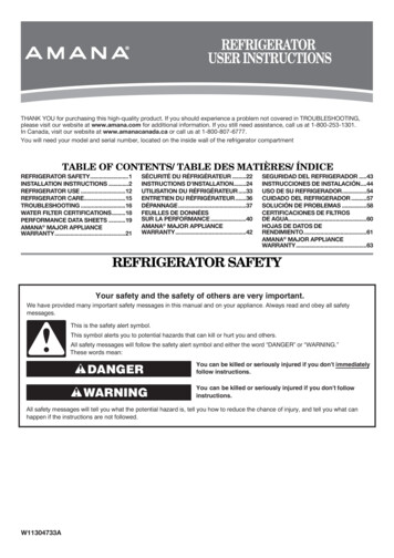
Installation RequirementsDoor Panels and Cabinetry Clearance - IF42/IF48 Series ModelsThe custom door panels and adjacent cabinetry for models series IF42 and IF48 must be designed so that there is sufficient clearancefor the doors to swing open. If the refrigerator is to be installed close to the wall, see Door Swing 90 on facing page.Refrigerator toCabinetry ClearanceDoor swing 110 actual size11/2" (3.8 cm)11/ 4" (3.2 cm)1" (2.5 cm)Refrigeratorside trimCabinetry110 doorstop position/ " (6.35 mm)14Hinge/ " (1.3 cm)12/ " (1.9 cm)341" (2.5 cm)lepancm)lepan(3.211 /4"cm)" (3.811 /2cm)rlayOve.51" (2).9 cm3 /4" (1).3 cm/ " (11 2kerBacrDooNOTE: For IF series models, rout thehinge side of the custom door panelsto a radius that is equal to at least halfthe thickness of the panel if a 130 door swing is desired. See AdjustDoors.Spacer panelWhen the doors are closed the refrigerator will extend beyond the face of the adjacent cabinetry to some degree.8
Installation RequirementsRefrigerator toCabinetry ClearanceDoor Swing 90 Actual SizeDoor swing 90 actual size1" (2.5 cm)/2" (1.3 cm)190 doorstop position/4" (1.9 cm)3Refrigerator toCabinetry ClearanceRefrigeratorside trimCabinetry/ " (6.35 mm)1 4Hinge/ " (1.3 cm)1 2/ " (1.9 cm)3 41" (2.5 cm)Overlay panelBacker panel11/2" (3.8 cm)11/4" (3.2 cm)1" (2.5 cm)3/4" (1.9 cm)/2" (1.3 cm)1DoorSpacer panelAllow a minimum of 4½” (11.4 cm) of space between the side of the refrigerator and a corner wall. More clearance may be needed ifthicker custom panels or custom handles are used. Do not overlook baseboards.9
Installation RequirementsCustom Panels and Handles - IF42/IF48 Series ModelsCustom overlay panels used with models IF42 and IF48 allow youto blend the exterior of your refrigerator into the overall kitchendécor, and to use custom handles for additional design flexibility.Panel SpecificationsImportant Information About Freezer Door OverlayPanels on Dispenser Models: There are two basic methods for paneling the freezer door ondispenser models:-- Frameless method The custom panels must have backer panels attached in orderto mount them to the refrigerator. It is most common to workwith three layers, as shown in the illustrations below. The threelayers consist of a decorative overlay panel, a ¹/8” (3.2 mm)spacer panel or spacer strips and a ¼” (6.4 mm) backer panel.-- Framed method In some cases, instead of constructing the panel using threelayers, the cabinet manufacturer may choose to work with asingle piece routed for the different dimensions. Follow thepanel dimension and placement instructions on the facing pageto be sure that the custom overlay panels will fit properly. To minimize panel weight, you may use 2” (5.1 cm) spacerstrips around the perimeter in place of full-sheet solid spacerpanels. The spacer strips must be set in at least 1” (2.5 cm)from the top, bottom and side edges of the backer panel. If youuse spacer strips, it is also recommended that you use two 2”(5.1 cm) strips horizontally centered for added support. For the grille and the door panels to be flush, the overlay doorpanel should be ¼” (6.4 mm) thicker than the overlay grillepanel. The framless method involves fabricating two separate panelsfor above and below the dispenser that slide into the trim frameon the door. The framed method involves fabricating a single overlay paneland attaching two separate sets of spacer and backer panelsabove and below the dispenser cutout (see facing page). Thecompleted panel slides into the trim frame on the door as asingle unit.IMPORTANT: The dispenser is recessed behind the overlaypanel for the freezer door. The edges of the overlay panel aroundthe bottom of the dispenser may be exposed to water duringnormal use. Seal the area around the dispenser to prevent waterseepage and damage. It is suggested that the edges of the panelaround the bottom of the dispenser be covered by waterproofmaterial to prevent damage to the finish over time.IMPORTANT: Install the custom panels only after moving the refrigerator intoplace (see page 16). The weight of the overlay panels cannot exceed:-- 50 lbs (23 kg) for the refrigerator door-- 30 lbs (13.5 kg) for the freezer door (total)-- 10 lbs (4.5 kg) for the top grilleOverlay panelOverlay panelSpacer panelSpacer panelSpacer panel/1 8"(3.2 mm)Spacer panel1/8"(3.2 mm)Overlay panelOverlay panelBacker panelBacker panelDoorDoor 1" Min.(2.5 cm)1" Min.(2.5 cm)Backer panelTrim frame5/8" to 3/4"Offsetdimension1/4"panelDoor/Grille trim(1.6 to 1.9 cm)Backer1/8"5/8" to 3/4"(6.4 mm)Offset dimension1/4"(3.2 mm)(1.6 to 1.9 cm)* The spacer panel offset must be a minimum1/8"(6.4 mm)of 1” (2.5 cm) from all four edges of each(3.2 mm)backer panel, including the edges next to thedispenser (on dispenser models).10
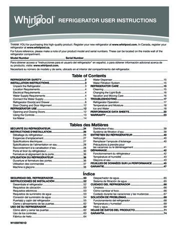
Installation RequirementsFreezer panel for dispenser modelsFrameless method: 2 overlay panels, Framed method: 1 overlay panel,2 backer panels2 backer panelsBackertop offset 16" (1.1 cm)AFreezer panel fornon-dispenser modelsRefrigerator panel forall modelsABA7Overlaypanel, topG24 ¹ 8 "(61.3 cm)23 "(59.4 cm)38Backerpanel, topDGTop freezer panelA35”(88.9 cm)23 8 "(59.4 cm)334 ³ 8 "(87.3 cm)DDispensercutout iscenteredleft to right11 5 8 "(29.5 cm)Backerpanel, bottomDDBackerhandle-sideoffset¹ 8 " (3.2 mm)E70¹ 2 "(179.1 cm)1115 16"(30.3 cm)70¹ 2 "(179.1 cm)71¹ 16 "(180.5 cm)G34 ³ 8 "(87.3 cm)Backerbottom offset¹ 8 " (3.2 mm)Bottom freezer panelGOverlay panelBacker panelHandle-sideoffset, top¹ 8 " (3.2 mm)GHandle-sideoffset, bottom¹ 8 " (3.2 mm)GGBackerpanel, topHandle-sideoffset, top¹ 8 " (3.2 mm)Overlaypanel, bottomGSingleoverlay panelG35”(88.9 cm)Backerpanel,bottomDHandle-sideoffset, bottom¹ 8 " (3.2 mm)GGBackerbottom offset¹ 8 " (3.2 mm)Backer bottom offset¹ 8 " (3.2 mm) GDecorative Overlay PanelsModelSeriesABCIF4217¹ 8” (43.5 cm)23¹ 8” (58.7 cm)40½” (102.9 cm)IF4819 5 8” (49.8 cm)265 8” (67.6 cm)46½” (118.1 cm)Top grille7 3/8"(18.7 cm)81/2"(21.6 cm)CGBackerbottomoffset1" (2.5 cm)FBacker PanelsGModelSeriesDEFIF4216 7 8” (42.9 cm)22 7 8” (58.1 cm)40½” (102.9 cm)IF4819 3 8” (49.2 cm)26 3 8” (67.0 cm)46½” (118.1 cm)G - Denotes top and bottom edges of backer panel that slide intotrim frame on door and top grille.Handles - IF42/IF48 Series ModelsB Before installing a custom panel assembly, you must install thecustom handle hardware. The handle and handle mountinghardware are not provided with the refrigerator. Dacor recommends handles with larger D-style pulls. Anyhandle designed for use with an appliance should producesatisfactory results. Handle kits are available through yourDacor dealer. Handle kits do not include the necessary mounting screwssince screw length required varies with the total thickness ofthe panels. The panel craftsman must determine and obtain theproper fasteners for the application. If using screws with thickheads, they must be countersunk into the panel before installingthe handles.IMPORTANT: Dacor does not advise the use of single pull knobs.ATrim frameDoorC20” Typ.(50.8 cm)36” Max.(91.4 cm)A. Countersunk screwB. HandleC. Door panel assemblyHandle Detail11
Installation RequirementsCustom Side Panels - IF42/IF48Inset Installation DimensionsCustom side panels may be needed when not enough space isavailable to have cabinets on both sides of the refrigerator orwhen the refrigerator is placed at the end of a cabinet run. Youmay choose an Inset or Recessed Inset panel installation formodels IF42 and IF48.2. If the panel is more than ³ 8” (9.5 mm) thick, rout the front edgeto allow the side panel to fit into the trim.1. Measure the distance from point A (as shown) to the backwall. Add ¹ 32” (0.8 mm) to this measurement to allow the sidepanel to fit into the trim.Refrigerator and Side Trim DimensionsThe width and height of a side panel are determined by the typeof installation you are planning.NOTES: The dimensions shown are actual product dimensions andmay not reflect the needed installation dimensions. The side panel should be a minimum of ½” (1.3 cm) thick toavoid warping. If the opening depth is 25” (63.5 cm) or more, you may want toinstall a support board on the rear wall.RefrigeratorBack wallAARecessed Inset Installation Dimensions1. Measure the distance from point B (as shown) to back wall.23 1/2”(59.7 cm)2. Route the front edge of the support board or attach a ³ 8” (9.5mm) board to hold the panel in the cabinet side trim.Back wallBASide Trim3/8” (9.5 mm)1/16” (1.6 mm)1/8” (3.2 mm)123/16” (4.8 mm)
Installation RequirementsCustom Side Panels - EF42/EF48Inset Installation DimensionsCustom side panels may be needed when not enough space isavailable to have cabinets on both sides of the refrigerator orwhen the refrigerator is placed at the end of a cabinet run. Youmay choose an inset, flush or recessed inset panel installation formodels EF42 and EF48.2. If the panel is more than ¼” (6.4 mm) thick, route the frontedge to allow the side panel to fit into the trim.1. Measure the distance from point A (as shown) to the backwall. Add 7 32” (5.6 mm) to this measurement to allow the sidepanel to fit into the trim.Refrigerator and Side Trim DimensionsThe width and height of a side panel are determined by the typeof installation you are planning.Back wallNOTES: The dimensions shown are actual product dimensions andmay not reflect the needed installation dimensions.AA The side panel should be a minimum of ½” (1.3 cm) thick toavoid warping. If the opening depth is 25” (63.5 cm) or more, you may want toinstall a support board on the rear wall.RefrigeratorFlush Installation Dimensions1. Measure the distance from point B (as shown) to the backwall.241/8”24¹ 8"(61.3 cm)(61.3cm)232311/16”¹¹ 16"(60.3 cm)(60.2cm)½"231/2”23(59.7 cm)(59.7cm)2. Attach the support board with a screw or adhesive that iscompatible with aluminum and wood.Back wallSide Trim1/4” (6.4 mm)11/64”(4.4 mm)3/16” (4.8 mm)BARecessed Inset Installation Dimensions1. Measure the distance from point C (as shown) to the backwall.7/32” (5.6 mm)13/32” (1.0 cm)2. Route the front edge of the support board or attach a¼” (6.4 mm) board to hold the panel in the cabinet side trim.5/8”(1.6 cm)Back wallCA13
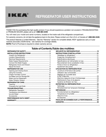
Installation InstructionsUnpack RefrigeratorWARNING1. Grasp both ends of the top grille.2. Push the top grille straight up, then pull straight out. Lay thegrille on a soft surface.BABTip Over HazardRefrigerator is top heavy and tips easily when notcompletely installed.Keep doors taped closed until refrigerator iscompletely installed.A. Top grilleB. Cabinet side trim3. Remove the six screws attaching each cabinet side trim to therefrigerator and remove the side trims.Use two or more people to move and installrefrigerator.Move Refrigerator into HouseFailure to do so can result in death or serious injury.WARNINGIMPORTANT: If you receive a damaged product, immediately contact yourdealer or builder. Do not install or use a damaged appliance. Do not remove the film on the outside until the refrigerator is inits operating position. All four leveling legs must contact the floor to support andstabilize the full weight of the refrigerator. Keep the cardboard shipping piece or plywood under therefrigerator until it is installed in the operating position.1. Remove and save the literature package bag taped to the sideof the refrigerator and the parts bag behind the grille. Removethe four brackets (two on each side) that attach the shippingbase to the refrigerator bottom.NOTE: Do not remove tape and door bracing until the refrigeratoris in its final position.2. If necessary, reduce the tipping radius. See Tipping Radius(page 5) for ceiling height requirements or Reduce TippingRadius for step-by-step instructions. If you do not need toreduce the tipping radius, proceed to Move the Refrigeratorinto House.Reduce Tipping Radius(if required)Before bringing the refrigerator into the home, be sure there isadequate ceiling height to stand the refrigerator upright. SeeTipping Radius (page 5).If you do not have adequate ceiling height to stand the refrigeratorupright, the tipping radius can be reduced by removing the topgrille and side trims (see the following chart).ModelReduced Tipping RadiusEF42, IF4288½” (224.8 cm)EF48, IF4889¼” (226.7 cm)Tip Over HazardRefrigerator is top heavy and tips easily when notcompletely installed.Keep doors taped closed until refrigerator iscompletely installed.Use two or more people to move and installrefrigerator.Failure to do so can result in death or serious injury.1. Place an appliance dolly under the left side of the refrigeratoras shown. Be sure to avoid damaging the side trims andhandles. Place the corner posts from the packing materialsover the trims and handles as appropriate. Slowly tighten thestrap.NOTE: Pass thedolly strap underthe handlesfor EF seriesmodels.2. Place piecesof the shippingcarton on thefloor when rollingthe dolly andrefrigerator into the house. Move the refrigerator close to thebuilt-in opening.3. Place top of cardboard carton or plywood under refrigerator.4. Stand the refrigerator up. First, place the left bottom edge ofthe refrigerator on the floor, stand the refrigerator upright andthen lower the right-hand side of the refrigerator to the floor.5. Do not remove the film on the outside.6. Reassemble the trim and top grille after the dolly has beenremoved from the refrigerator.14
Installation InstructionsInstall Anti-Tip BoardsConnect Water SupplyIMPORTANT:Read all directions before you begin. To avoid tipping during use, the solid soffit must be within 1”(2.5 cm) maximum above the refrigerator. If the solid soffitis higher than 1” (2.5 cm) or one is not available, then therefrigerator must be braced.IMPORTANT: If you turn the refrigerator on before the water lineis connected, turn the ice maker OFF. It is recommended that board(s) be installed before therefrigerator is installed.NOTE: If the existing water line meets the Water SupplyRequirements, see Connecting to Refrigerator. Board(s) must be long enough to fully
Floor must support the refrigerator weight, more than 600 lbs (272 kg), door panels and contents of the refrigerator. Ceiling height must allow for side tipping radius. See Tipping Radius. Location should permit doors to open fully. See Door Swing Dimensions. Location must permit top grille removal. See Opening Dimensions.