Transcription
9Optimizing the Heat TreatmentProcess of Cast Aluminium AlloysAndrea Manente1 and Giulio Timelli21Cestaro2UniversityFonderie Spaof Padova, Department of Management and EngineeringItaly1. IntroductionThe unfailing increased use of light alloys in the automotive industry is, above all, due tothe need of decreasing vehicle’s weight. The same need has to be taken into account in orderto face up also both energetic and environmental requirements (Valentini, 2002). In terms ofapplication rates, Al and its alloys have an advantage over other light materials. Thereduced prices, the recyclability, the development of new improved alloys and castingprocesses, the increased understanding of design criteria and life prediction for stressedcomponents and an excellent compromise between mechanical performances and lightnessare the key factors for the increasing demand of Al alloys. A consolidated example ofaluminium alloy employment regards the production of wheels, which, together with animproved aesthetic appearance, guarantees an improvement of driving, like directedconsequence of the inertia reduction. These critical safety components are somewhat uniqueas they must meet, or exceed, a combination of requirements, from high quality surfacefinish, as wheels are one of the prominent cosmetic features of cars, to impact and fatigueperformance. Due to their excellent castability and good compromise between mechanicalproperties and lightness, AlSiMg alloys are the most important and widely used castingalloys in wheel production (Conserva et al., 2004). Further, the increasing application ofthese alloys has been driven by the possibility to improve the mechanical properties of castcomponents through the use of heat treatments. Various heat treatments, e.g. differentcombinations of temperatures and times, have been standardized by AluminiumAssociations and they are used in Al foundry depending on the casting process, the alloytype and the casting requirements (ASM Handbook, 1990). Standard T6 heat treatment isgenerally applied in wheel production. This heat treatment provides two beneficial effectsfor cast aluminium alloy wheels: an improved ductility and fracture toughness throughspheroidization of the eutectic silicon particles in the microstructure and a higher alloy yieldstrength through the formation of a large number of fine precipitates which strengthen thesoft aluminium matrix (Zhang et al., 2002). The T6 heat treatment comprises three stages(ASM Handbook, 1991): solution heat-treating, quenching and artificial aging.Solution heat-treating at relatively high temperature is required to activate diffusionmechanisms, first, to dissolve Mg-rich phases formed during solidification and, then, tohomogenize the alloying elements, such as Mg and Si, so as to achieve an elevated yieldstress subsequent ageing (ASM Handbook, 1991). Further, the solution heat treatmentwww.intechopen.com
198Recent Trends in Processing and Degradation of Aluminium Alloyschanges the morphology of eutectic Si from polyhedral, or fibrous morphology in themodified alloys, to globular structure. Various efforts have been made to investigate theeffects of solution temperature and time on microstructure and mechanical properties ofAlSiMg foundry alloys (Zhang et al., 2002; Rometsch et al., 1999; Pedersen & Arnberg, 2001;Shivkumar et al., 1990a; Dwivedi et al., 2006; Taylor et al., 2000; Langsrud & Brusethaug,1998; Cáceres et al., 1995; Cáceres & Griffiths, 1996; Wang & Cáceres, 1998).Quenching is usually carried out to room temperature to obtain a supersaturated solidsolution of solute atoms and vacancies, in order to achieve an elevated strengtheningsubsequent ageing (ASM Handbook, 1991; Liščič et al., 1992; Komarova et al., 1973; Totten etal., 1998; Totten & Mackenzie, 2000). The most rapid quench rate gives the best mechanicalproperties, but it can also cause unacceptable amounts of distortion or cracking incomponents (Auburtin & Morin, 2003). Thus, parts of complex shape, often with both thinand thick sections, are commonly quenched in a medium that provides a slower cooling.This quenchant can be hot water, an aqueous solution of polyalkylene glycol, or other fluidmedium such as forced air or mist. In this way the heat transfer coefficient between the pieceand the quenchant is reduced, the heat transfer from the surface is delayed and a moreuniform temperature between the surface and the centre is obtained (Liščič et al., 2010;Totten et al., 1998; Totten & Mackenzie, 2000; Bates, 1987; Bates, 1993). Therefore, a balancebetween fast cooling and distortion minimization is required in quenched components.Artificial ageing consists of further heating the casting at relatively low temperatures (120210 C) and it is during this stage that the precipitation of dissolved elements occurs. Theseprecipitates are responsible for the strengthening of the material. In AlSiMg alloys, thedecomposition of the supersaturated solution begins with the clustering of Si atoms. Thisclustering leads to the formation of coherent spherical GP zones, consisting of an enrichmentof Mg and Si atoms, that elongate along the cube matrix direction to develop into a needleshape coherent β″ phase. With prolonged ageing, the needle shaped GP zones grow to formrods of an intermediate phase, β′, which is semicoherent with the matrix. The final stable βMg2Si phase forms as an incoherent platelets on the α-Al matrix and has ordered facecentered-cubic structure. Several studies have been made to investigate the effect of artificialageing temperature and time on strengthening mechanism of cast AlSiMg alloys. Ageing inthe temperature range 170-210 C gives comparable peak yield strength (Rometsch &Schaffer, 2002; Alexopoulos & Pantelakis, 2004), and, with higher temperatures, the time topeak can be shortened. At ageing temperatures higher than 200 C, the β″ phase issubstituted by the β′, which contributes less to strengthening (Eskin, 2003).It is of vital importance to consider both the foundry process and the T6 heat treatment onthe whole, in order to achieve the required performances and specific properties (Merlin etal., 2009). While the benefit of T6 heat treatment is accepted, the additional cost andproduction time associated with such a heat treatment are substantial. Considering thewhole production cycle of a standard automotive aluminium alloy wheel made by a lowpressure die-casting process (LPDC), the casting process normally takes less than 6 min,while a typical T6 heat treatment cycle may take more than 10 h. This means that shorteningthe total time of the T6 heat treatment cycle has a great impact on productivity andmanufacturing cost.In the present work, some process variables, which play a key role in production cycle ofwheels have been investigated and improved. An integrated methodology for developingand optimizing the production and the final quality of A356-T6 18-inch wheels, in terms ofcasting distortion and hardness, is proposed. This study focuses on examining both thewww.intechopen.com
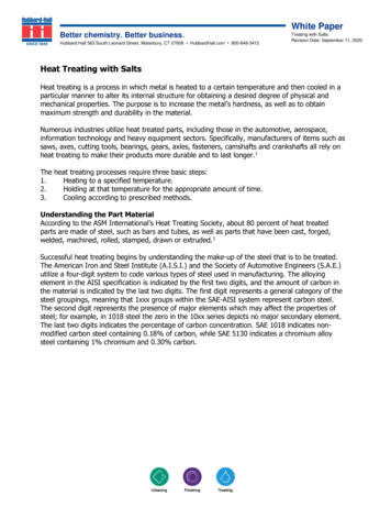
199Optimizing the Heat Treatment Process of Cast Aluminium Alloyseffect of cooling rate on wheel distortion and hardness during the post-cast and quenchingsteps, and the influence of the solutionizing temperature and time, and the powder coatingcycles on the microstructure and mechanical properties of the 18-inch wheels.2. Material and experimental techniquesAn approach for optimizing wheel production has been applied on A356-T6 18-inch wheels,which are 5-spoke wheels in the T6 temper, with a diameter of 457 mm and a rim width of203 mm. Fig. 1 shows a sketch of the analysed wheel, which is generally cast by LPDC. Thecasting has a weight of about 18 kg.Fig. 1. Sketch of the low-pressure die-cast wheel analysed; the ingate is located in the hubregion2.1 Alloy and casting parametersThe cast wheels were produced with an AlSi7Mg alloy (EN AC-42100, equivalent to the USdesignation A356), whose composition is indicated in Table 1. The material was melted in afurnace set up at 730 5 C. The melt was degassed with a rotary impeller by using nitrogenand modified with Sr-containing master alloy. AlTi5B1 rod type grain refiner was alsoadded to the molten metal. The hydrogen level was evaluated before casting through aReduced Pressure Test 0.265Zn0.004Ti0.126Sr0.0279Table 1. Chemical composition of A356 alloy used in the present work (wt.%)The die cavity is geometrically complex and is comprised of four sections: a bottom die, twoside die sections, and a top die. These die sections are made by an AISI H13 tool steel. Thetemperature in the die, measured with thermocouples, was in the range of 450-520 10 C.The casting process is cyclic and begins with the pressurization of the furnace, whichcontains a reservoir of molten aluminium. The excess pressure in the holding furnace forcesthe molten aluminium to fill the die cavity in 60 4 s with a final pressure of 0.4 0.015 bar.An overpressure of 1.2 0.03 bar, reached after 10 2 s from the end of the filling, was thenapplied for 210 5 s. During solidification, cooling rates are controlled by forcing air (2–3bar) through internal channels in the top and bottom dies, at various times during castingwww.intechopen.com
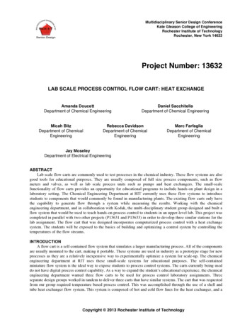
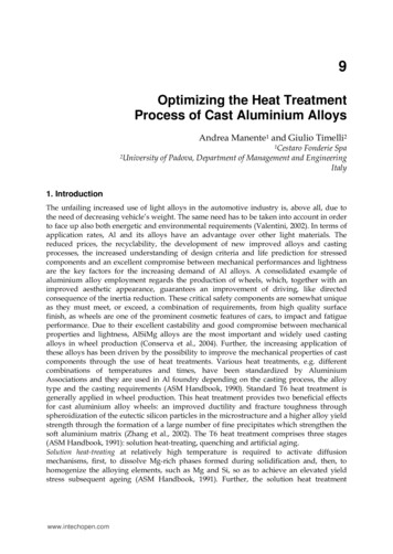
200Recent Trends in Processing and Degradation of Aluminium Alloyscycle. On the side dies, cooling can be ensured by air jets, aimed at various sections of theexterior face. After the complete solidification, the side dies open and the top die is raisedvertically. The wheel remains fixed to the top die prior to be ejected onto a transfer trayrolled under the top die. The die is then closed and the cycle begins again. Typical cycletimes are 5–6 min. The wheel was then automatically picked up by a robot and cooled. Toobtain a set of different cooling rates, water in the temperature range of 30-90 C wasadopted. Slow cooling rate in air was also used.2.2 Heat treatment and powder coating cycleThe wheels were T6 heat treated in an industrial plant, whose lay-out is shown in Fig. 2(Manente, 2008). The lay-out consists of a one-way line, where the wheels, loaded in suitablesteel frame (handling unit), follow and complete the whole heat treatment cycle.Fig. 2. Lay-out of the T6 heat treatment plant used in the present work (Manente, 2008)A robot provides for loading 30 wheels in a five plane basket (Fig. 2 – Stage A). The basket isthen moved into an air circulating tunnel furnace, where it is driven forward in 30consecutive steps (Fig. 2 – Stage B). In the first 6 steps, the wheels are heated up to the set upsolution temperature, while in the further steps they are maintained at temperature. Thewheels were solution treated at 540 5 C for 4, 5, 6, 7 and 8 hours (including heat up time)and immediately quenched (Fig. 2 – Stage C). The quenched delay was measured to be 20 s.To obtain a set of different quench rates, water at different temperature was adopted asquenchant. The water temperature ranged from 50 to 95 C. Slow quenching in air was alsoused. Table 2 shows the targeted and achieved quench water temperatures.TargetedAchieved50486058Water temperature ( C)707580856775818690899594Table 2. Targeted and achieved temperature of water quenchingThe wheels are subsequently transferred to an air circulating tunnel furnace, where theyartificial aged (Fig. 2 – Stage D). This stage consists of 20 steps, where in the first 4 steps, thewheels are heated up to the set up ageing temperature, while in the further steps they aremaintained at temperature. The wheels were artificially aged at 145 5 C for 4 hours afterwww.intechopen.com
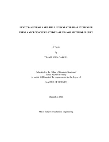
Optimizing the Heat Treatment Process of Cast Aluminium Alloys201solutionizing and water quenching (T6). This is a typical underageing treatment used in themanufacture of wheels. The rejected or sound wheels are finally moved to Stages E or Frespectively, as indicated in Fig. 2.After machining and cleaning operations, the wheels are generally powder coated and leftinside an air electric furnace at 170 5 C for 1 hour, including the heat-up time. Fig. 3.shows a typical thermal cycle of the wheels during powder coating. In the present work theeffect of coating cycles has been studied by varying the number of cycles from 1 to 3.Fig. 3. Thermal cycle used for powder coating wheels; thermocouples are placed directlyinto the furnace chamber and embedded into the hub and the spoke region of the wheel2.3 Microstructural characterizationDetailed microstructural characterisation of the as-cast and T6 heat treated wheels wascarried out using an optical microscope and a scanning electron microscopy (SEM)equipped with an energy-dispersive spectrometer (EDS). The quantitative analysis ofvarious phases in the microstructure were characterised using an image analyser software.The samples, drawn from the hub, the spoke and the rim region of the wheels, weremechanically prepared to a 3-µm finish with diamond paste and, finally, polished with acommercial fine silica slurry. Average secondary dendrite arm spacing (SDAS) values wereobtained using the linear intercept method. A series of at least 10 photographs of eachspecimen were taken and several measurements were done, in order to obtain reliable meanvalues. To quantify the microstructural changes during solution heat treatment, the imageanalysis was focused on the size and shape factor of the eutectic Si particles. Size is definedas the equivalent circle diameter (d); the shape factor (α) is the ratio of the maximum to theminimum Ferets. To obtain a statistical average of the distribution, a series of at least 15photographs of each specimen were taken; each measurement included more than 700particles. The secondary phases, such as the Mg-rich particles and the Fe-rich intermetallics,were excluded from the analysis. Further, the polished specimens were chemically etched ina Keller etchant (7.5 mL HNO3, 5 mL HCl, 2.5 mL HF and 35 mL H2O).2.4 Distortion and hardness testingBrinell hardness measurements were carried out throughout the casting, on well definedlocations, by using a load of 250 kgf, according to the standard ASTM E92-82. An averageover 15 measurements was taken to evaluate the hardness of each wheel. Target hardnessvalues after complete T6 heat treatment range between 90 and 95 HB.www.intechopen.com
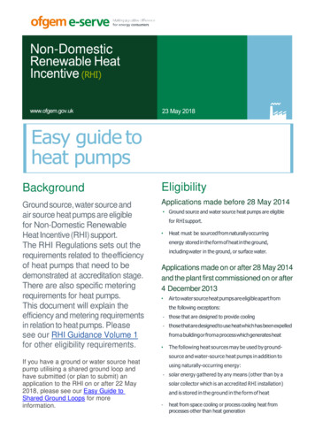
202Recent Trends in Processing and Degradation of Aluminium AlloysThe amount of distortions of the wheels was carried out after post-cast cooling (ε) and afterquenching (εt), by using a circular gauge, which allows to calculate the maximum variationof the diameter of the wheel along the rim. Generally, the maximum accepted distortion of awheel is 1.5 mm, while wheels with higher distortions are normally rejected. This is a typicalstandard used for wheel manufacturing (Manente, 2008).3. Results and discussionThe methodology to analyse and optimize the quality of A356-T6 18-inch wheels, in terms ofcasting distortion and hardness, and to optimise the whole process manufacturing is basedon different steps:analysis of as-cast wheels;analysis of solution heat treated wheels;analysis of quenched wheels;analysis of powder coated wheels.3.1 As-cast wheel3.1.1 Thermography measurementsA series of infrared (IR) thermographs was taken during wheel ejection from the top die andjust prior the wheels were water cooled, to obtain 2D temperature maps of the casting surface.Fig. 4 shows an IR image of the wheel surface and the top die. The wheel stays on thetransfer tray set under the top die. The top die shows a temperature between 435 and 495 Cand the highest temperature is concentrated at the ingate, i.e. the hub region. These thermalvalues are comparable with the reading of the thermocouples which are located few mmunder the die surface. The small differences can be related to the emissivity coefficient set upin the IR camera or some small variations in the experimental process parameters, influencingthe thermal evolution and distribution of the die. High temperatures are localised in the diearound the thickest regions of the casting, i.e. the hub and the spoke (to some extent), wherethe die receives a great quantity of solidification heat. Contrary, the surface temperature ofthe wheel shows a temperature range of 340-420 C, with the lowest temperature in the rimand the highest in the zone of the wheel between the spoke and the rim (Fig. 4). Under theseconditions, the wheel was then automatically picked up by a robot and cooled.Fig. 4. Infrared thermal mapping of the wheel during extraction from diewww.intechopen.com
203Optimizing the Heat Treatment Process of Cast Aluminium Alloys3.1.2 Microstructural observations of as-cast wheelsThe microstructure of the modified A356 alloy consists of a primary phase, α-Al solidsolution, and an eutectic mixture of aluminium and silicon. The α-Al precipitates from theliquid as the primary phase in the form of dendrites. The scale of microstructure in differentzones of the wheel was characterized by means of SDAS measurements. The coarseness ofthe microstructure varied inversely with the casting thickness, i.e. the solidification rate.Typical microstructure of the as-cast wheel is shown in Fig. 5, referred to the hub, spoke andrim zones, corresponding to 55, 36 and 22 μm in SDAS respectively. Local solidificationtimes (tf) were estimated by means of SDAS measurements through the followingrelationship (Dantzig & Rappaz, 2009): C Γ sl D l ln eut C 0 SDAS 5.5 t m ( 1 k )( C C ) f l0eut0 13(1)where Γsl is the Gibbs-Thomson coefficient, Dl the diffusion coefficient in liquid, ml the slopeof the liquidus curve, k0 the partition coefficient, C0 and Ceut are the initial alloyconcentration and the eutectic composition respectively. The solidification time wasestimated to be 184 s in the hub, 52 s in the spoke and 12 s in the rim zone. The solidificationsequence is approximately directional, starting at the outermost point of the wheel (rim) andcontinuing toward the centre of the wheel (hub), where the ingate is located.Fig. 5. Microstructure of as-cast wheel with reference to the different positions analysedwww.intechopen.com
204Recent Trends in Processing and Degradation of Aluminium AlloysCoarse intermetallics compounds, such as Mg-rich particles and Fe-rich intermetallics, bothin the form of coarse α-Al(FeMnSi) particles and needle-shaped β-Al5FeSi, were alsoobserved, especially in the hub region where the solidification rate is lower (Fig. 6).Fig. 6. Optical micrograph showing secondary phase particles in hub region; the eutecticsilicon particles are present in the interdendritic channels, β-Al5FeSi phase appear withtypical needle shape and β-Mg2Si particles as Chinese scriptAs it has been well established (Apelian et al., 2009; Kashyap et al.,1993), the eutectic Siphase in the microstructure of the Sr-modified alloy exhibits a fibrous morphology under ascast conditions. The mean equivalent diameter d of eutectic Si particles increasesapproximately from the rim ( 0.8 μm) toward the spoke ( 1.6 μm) and the hub region( 2 μm). It was established that by reducing the cooling rate, the microstructure ischaracterised by coarse eutectic Si particles, while by reducing the solidification time theformation of a high number of fine Si particles is predominant. Further, the size distributionof Si particles was investigated in several studies (Tiryakioglu, 2008; Shivkumar et al., 1989;Grosselle et al., 2009) and found to follow the three-parameters lognormal distribution asfollowsf (d) (ln( d τ) μ )2 1exp 2σ 2( d τ)σ 2 π (2)where d is the diameter of Si particles, τ the threshold, σ the shape and μ is the scaleparameter.3.1.3 Distortion behaviour in the as-cast temperThe different cooling media produced different amount of distortions in the 18-inch wheels.Generally, the distortion was in the range between 0.6 and 1.1 mm. Fig. 7 compares thewheel distortion induced by air or water cooling. It is evidenced how water temperaturehigher than 70 C produces similar distortions as air cooling (ε 0.6 mm).By increasing the water temperature, the amount of distortions decreases. This relationshiphas been estimated by linear regression analysis, using the coefficient of the determinationR2 to evaluate the quality of the least-squares fitting (Fig. 7). When R2 is equal to 1, the fit iswww.intechopen.com
205Optimizing the Heat Treatment Process of Cast Aluminium Alloys1.41.2Distortion, ε (mm)10.80.60.40.2Linear fit (R2 0.94)0Air20406080Water temperature ( C)100Fig. 7. Wheel distortion as a function of the cooling medium, i.e. air and water at differenttemperature, after ejection from the die; standard deviations are given as error barsperfect. In the considered range of water temperature, the distortion ε can be describedaccording to the following regression model (R2 0.94):ε 0.009 T 1.342(3)where T is the water temperature in C. Every wheel cooled in air and water shows a certainwarp degree, which is more or less evident. The amount of distortions can reach criticallevel that compromises the functionality of the wheel too, as shown in Fig. 8. ResidualFig. 8. Wheel distortion after post-cast cooling in water at a temperature of 30 Cwww.intechopen.com
206Recent Trends in Processing and Degradation of Aluminium Alloysstresses originate from differential thermal gradient and contraction during post-castcooling. The wheel is extracted from the die at high temperature, as previously shown, andrapidly cooled. Therefore, the stress is so high that plastic deformation in the casting, freefrom the die, occurs. Generally, the casting distortion is more pronounced in casting ejectedfrom the die at high temperature and in components showing drastic thickness changes(ASM Handbook, 1991). Further, higher the temperature difference between the casting andthe cooling medium, greater will be the residual stresses and the casting distortion (Bates,1987).3.2 Solution heat treatment3.2.1 Evolution of eutectic silicon particlesThe influence of the solution heat treatment time on the microstructure of 18-inch wheels isshown in Fig. 9. The micrographs refer to the hub, which is the thickest zone of the wheelwith a coarse microstructure, SDAS 55 μm. In the range of solution temperature and timesused, and due to the high diffusion rate of Mg in the α-Al matrix, the Mg bearing phases arecompletely dissolved and not more evident even in the coarse microstructure of the hub.These findings are in agreement with the results reported elsewhere (Rometsch et al., 1999;Zhang et al., 2002).After 4 h of solution heat treatment at 540 C, the Si particles becomecoarser and the interparticle distance increases (Fig. 9b). Rayleigh instability occurs; siliconparticles undergo necking and are broken down into fragments. Due to the instability of theinterfaces between the two different phases and a reduction in the total interface energy,spheroidization and coarsening processes occur. A prolonged solution treatment leads toextensive coarsening of the particles, with a small effect on the spheroidization level (Fig. 9cf). The interparticle spacing increases too. Because the coarsening and spheroidization arediffusion-controlled processes (Greenwood, 1956), they are directly proportional to thesolution temperature and time. These findings are in agreement with Meyers (Meyers, 1985).Further, previous results (Zhang et al., 2002) showed there exists a decrease in average Sicrystal size after short solution heat treatment, before the average size increases. From theliterature, the most severe coarsening of eutectic Si particles takes place between 25 and 400minutes of solution treatment of the unmodified alloy, while the average particle sizeincreased more evenly in the modified alloy (Pedersen, 1999). It has been stated that thetypical growth rates for gravity die castings are in the range of 0.02 to 0.07 μm/h (Pedersen,1999).The results of the Pedersen’s work on the quantitative variation in the Si particle size andshape factor of an AlSi7Mg0.3 alloy with similar microstructural scale as the hub of thewheel (SDAS 54 μm) as a function of solution time are reported in Fig. 10. The Si growth isestimated in terms of variation of the equivalent radius with respect to t1/3, as defined by theordinary Lifshitz-Slyozow-Wagner model (Liftshitz & Sloyozov, 1961):R 3 R 03 8 D C0 γ V 2t9 R gas T(4)where T and t are the temperature and time, respectively; R is the radius of the particle; R0 isthe initial radius at t 0; Rgas is the gas constant; V is the molar volume; C0 is the equilibriumconcentration of structures in matrix; γ is the surface energy of the particle; and D is thediffusion coefficient. The regression analysis leads to R2 equal to 0.97, indicating thereliability of the model.www.intechopen.com
Optimizing the Heat Treatment Process of Cast Aluminium Alloys207Fig. 9. Eutectic Si particles in the hub region of A356-T6 18-inch wheels; the alloy has beensolubilised at 540 C for various time: (a) as-cast, (b) 4, (c) 5, (d) 6, (e) 7 and (f) 8 hours. Siliconparticles undergo necking and are broken down into fragments, then, spheroidization andcoarsening mechanisms occurFig. 10b shows the distribution of the eutectic Si particles as a function of the shape factor forsamples heat treated at 540 C for various time. Pedersen observed how the particlesundergo great changes in shape factor α distribution after short times (30 minutes) ofsolution heat treatment; the fraction of particles with a smaller α parameter is immediatelyreduced, while the number of particles with a greater α parameter is increased. Similarwww.intechopen.com
208Recent Trends in Processing and Degradation of Aluminium Alloys230251.620Frequency (%)Equivalent radius, R (µm)As cast30 min60 min120 min240 min480 min1.20.815100.45Linear fit (R2 0.97)000246Time of the solution heat treatment, t 1/3 (min)800.10.20.3(a)0.4 0.5 0.6 0.7Shape factor, α0.80.91(b)Fig. 10. (a) Linear regression analysis of eutectic Si equivalent radius with t1/3; the point zeroin the time axis represents the as-cast condition; (b) frequency distribution of the shapefactor α after solution treatment at 540 C for different times (Pedersen, 1999)2.8Equivalent diameter, d (µm)2.4Hub2Spoke1.6Rim1.20.8As-castSolution treatment 540 C for 6h0.4203040SDAS (µm)5060Fig. 11. Average diameter d of the eutectic Si particles as a function of SDAS; data refer tothe different positions of the as-cast and solution heat treated wheelschanges in particle distribution are not observed by increasing the solution times within 4hours, even if the distribution curves flatten with solution time and their peaks move to thewww.intechopen.com
Optimizing the Heat Treatment Process of Cast Aluminium Alloys209right toward higher α values. Only after 8 hours solution time, the shape factor distributionmoves to higher α values. The eutectic Si particles in AlSi7Mg gravity-cast alloys crackprogressively with increasing applied plastic deformation, and the crack is favourable forthe larger and longer particles, even if the progression of particle cracking is more gradualin a finer microstructure (Cáceres & Griffiths, 1996). In addition, it was observed that thepopulation of cracked particles is distributed according to the α·d parameter and ischaracterized by its average α·d value.Since solidification rate has a dramatic effect on the size and morphology of eutectic Siparticles, it is important to be aware of the influence of the solidification rate on the requiredminimum solution time for realizing the required coarsening and spheroidization. It wasreported (Shivkumar et al., 1990c) that 3-6 h at 540 C is the optimal time for a Sr-modifiedsand-cast A356 alloy; while 30 min at 540 C is needed for a low-pressure die-castSr-modified A356 alloy with SDAS of 25 μm (Zhang et al., 2002). Fig. 11 shows the effect of asolution treatment at 540 C for 6 h on the Si particle size in the different positions of thewheels ,where different microstructural scales were observed. The coarsening mechanism isfaster in the rim and spoke region, where SDAS is about 22 and 36 μm respectively. Whilethe coarse microstructure of the hub presents slower coarsening of Si particles, as indicatedby the values of equivalent diameter in the as-cast and solution heat treated temper.3.2.2 Partial meltingThe increase of solution temperatures for the heat treatment of the wheels would bedesirable since it increases the diffusion rate of Si atoms in the Al matrix, leading to rapidfragmentation and coarsening mechanism of eutectic Si particles, and, therefore, to shortenthe total time of the T6 heat treatment cycle. It was demonstrated that for a given shortsolution treatment time of 9.5 minutes, increasing the temperature from 540 to 550 C thenumber fraction of Si particles with a diameter of greater than 1 μm increases by more than10%. Similar changes in the distribution of the shape factor for Si particles are observed byincreasing the solution temperature, that is the number fraction of the particles with a shapefactor of greater than 0.5 increases by approximately 10% (Zhang et al., 2002). Earlier works(Shivkumar et al., 1990b) showed that extremely high coarsening occurred at temperaturesgreater than 540 C for A356.2 alloys. However, the major problem associated with higherheat treatment temperatures remains the liquid phase formation, which increases withtemperature.In the present work, the possibility to heat the wheels at higher solution temperature wasevaluated. A Fourier thermal analysis was carried out to determine the evolution of thesolid fraction during solidification of the A356 alloy used for wheel production. A detaileddescription of the equipment, the casting procedure, and the process parameters is givenelsewhere (Piasentini et al., 2005). The relationship between fraction of solid (fs) andtemperature of solidifying
2.2 Heat treatment and powder coating cycle The wheels were T6 heat treated in an industrial plant, whose lay-out is shown in Fig. 2 (Manente, 2008). The lay-out consists of a one-wa y line, where the wheels, loaded in suitable steel frame (handling unit), follow and co mplete the whole heat treatment cycle. Fig. 2.