Transcription
DSP-FOMFiber Optic MeterService Information Sheet for Serial Numbers 79370000IntroductionParts and Warranty ServiceThis Service Information Sheet provides thefollowing service information for the DSP FiberOptic Meter (hereafter referred to as the FOM) withserial numbers 79370000.The FOM is warranted to be free from defects inmaterial and workmanship for one year, whileunder normal use. Parts and repairs are warrantedfor 90 days. Parts and warranty service informationSpecificationsTheory of operationCleaning proceduresRequired equipmentPerformance testsProcedures for disassembling andreassembling the FOM Calibration adjustments Parts and accessories lists Schematic Diagram showing calibration measurementand adjustment pointsFor operating instructions, refer to theDSP-FOM/DSP-FTK Fiber Optic AccessoryInstruction Sheet.Refer to the Instruction Sheet for the completewarranty statement.To order parts, or for warranty service, contactFluke as follows:U.S.A.: 1-888-993-5853Canada: 1-800-363-5853Europe: 31-402-675-200Japan: 81-3-3434-0181Singapore: 65-738-5655Anywhere in the world: 1-425-446-4519For operating assistance in the USA, call1-800-283-5853.Visit the Fluke Networks web site atwww.flukenetworks.com.PN 616141September 1996, Rev. 2, 1/02 1996-2002 Fluke Networks, Inc. All rights reserved. Printed in USA. Product names are trademarks of their respective companies.
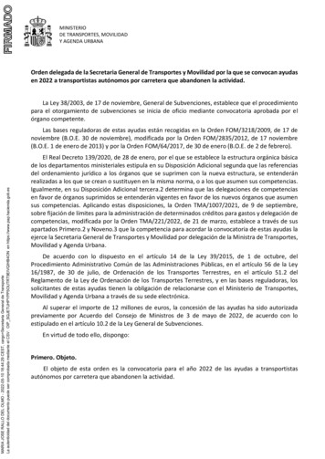
DSP-FOMFiber Optic MeterSpecificationsAccuracy is specified for a period of one year aftercalibration, at 18 C to 28 C (64 F to 82 F) withrelative humidity to 90%. Specifications are shownin Table 1.Table 1. Specificationslight to be measured into the FOM. The RJ45connector outputs a calibrated voltage via a cable tothe host CableMeter test tool. Other signals presentat the RJ45 connector are analog levels indicatingthe selected wavelength and a full-scale voltagereference for determining the battery status.Switch Positions and I/OSlide switch SW1 is a 2-pole switch. One pole(pin 5) applies the battery voltage to the voltageregulator U3. Battery voltage is also applied to oneof the voltage dividers R23/R24, R25/R26, orR19/R20. Each of these dividers generates ananalog level of 0 V to 0.53 V (referenced to analogground), which is proportional to the batteryvoltage. This analog level, which appears at pin 4,3, or 2 of connector J4, indicates which wavelengthhas been selected. J4 provides output to theCableMeter test tool.CalibratedWavelengths850 nm, 1300 nm, and 1550 nmMeasurementRange 3 dBm to -50 dBmMeasurementAccuracy* 0.25 dB at -10.0 dBm and25 C (77 F)Resolution0.1 dB (1 mV)Display Resolution0.01 dB (0.001 µW)Detector Type1 mm (0.04 in) GermaniumConformanceIEC 1010-1Optical AdapterSTI/O ConnectorRJ45 8-pin with ground shieldOutput VoltageDynamic Range: -0.02 V to 0.55 VOperatingTemperature0 C to 40 C(32 F to 104 F)StorageTemperature-20 C to 70 C(-4 F to 158 F)Power Supply and Low BatteryDetectionDimensions11.4 cm x 6.4 cm x 3.8 cm(4.5 in x 2.5 in x 1.5 in)Weight141.7 g (5 oz)Battery Type9 V AlkalineBattery Life90 hours typicalWhen power is enabled with SW1, the batteryvoltage (minus a diode drop) appears at pin 5 ofvoltage regulator U3. U3 generates a 5 V output onpin 4 and a 2.5 V output on pin 6, which is used asa rail-splitting analog ground.* For field strengths between 1 V/m and 3 V/m add 6 dB.Theory of OperationThis section provides theory of operation for theFOM. Refer to the schematic in Figure 1.General DescriptionThe FOM is an optical power to voltage converterdesigned to interface with a DSP CableMeter and CableAnalyzer test tool. The FOM iscalibrated to convert optical power to voltage atwavelengths of 850 nm, 1300 nm, and 1550 nm.A slide switch on the face of the FOM enables theunit and selects the calibration for one of the threewavelengths. A ST optical connector couples the2The other pole of SW1 (pin 6) applies the 5 Vregulator output to the appropriate potentiometer(R1, R2, or R3) controlling the wavelength-specificreference current. Photo diode PD1 is the opticalinput interface.A low battery condition is indicated when thevoltage from the selected divider R23/R24,R25/R26, or R19/R20 drops below 0.26 V relativeto analog ground (battery voltage of 6.2 V). Thefull-scale voltage reference of 0.53 V is generatedby divider R21/R16 between the 5 V supply and the2.5 V analog ground. U2A buffers this reference.Optical Receivers and A/DMeasurementsThe logarithmic optical power to voltage circuit iscomprised of Q1, U1, PD1, and associated resistorsand capacitors. Q1B, part of a dual, bipolartransistor, receives a reference current from one ofthree potentiometers. Q1A receives the signalcurrent from PD1. The output at U1B, pin 7, isproportional to the logarithm of the difference
Service Information Sheet for Serial Numbers 79370000Cleaning the Optical Connectorbetween the reference current and the signalcurrent; therefore, the output is a linear function ofthe optical power received by the photo detector. Atypical output at U1, pin 7 is 23 mV per dB ofoptical power, plus a 69 mV offsetThe reference current adjustment potentiometersR1, R2, and R3 control the zero offset for the threecalibrated wavelengths. Potentiometer R10 trimsthe final output slope to 10 mV per dB. The outputof U1B is buffered by U2B. R7 providestemperature compensation to null some of thethermal drift of Q1A and Q1B.Cleaning the Optical ConnectorMost problems with optical power meters resultfrom contaminated connectors. Therefore, alwaysclean the connector before troubleshooting orcalibration.To clean the FOM ST connector, wipe it gentlywith an optical-grade tissue or swab dampened withoptical-grade alcohol. To remove loose dirt anddust from the connector, use filtered, compressedair.Always cover the connector with a dust cap whenthe unit is not in use.Required EquipmentThe following equipment is required for servicingthe FOM: 0-10 V power supplyFluke 187 digital multimeter or equivalentOptical power meter calibrated at 850 nm,1300 nm, and 1550 nm traceable to NISTStandards850 nm laser source; Po -10 dBm1300 nm laser source; Po -10 dBm1550 nm laser source: Po -10 dBmVariable MM optical attenuatorVariable SM optical attenuatorFluke DSP CableMeter test tool1 m fiber optic patch cables, 2 required2 m UTP patch cable (supplied with theCableMeter test tool)Performance TestsUse the performance tests to confirm that the FOMis working properly. If the FOM fails any of thesetests, clean the fiber connectors, verify that theconnections are solid, then retest the FOM. If theFOM still fails a test, it needs calibrationadjustments or repair.DSP-FOM Detection1. Turn the CableMeter test tool knob to SETUP.Use the arrow keys to select TESTSTANDARD, CABLE TYPE; then pressE. Use U D (and Page Up/PageDown softkeys if necessary) to select theapplicable standard for the DSP-FOM; thenpress E. Use the arrow keys to selectMultimode as the cable type; then pressE.2. With the FOM not connected to the CableMetertest tool, turn the test tool knob to SINGLETEST; then press E. Verify that thetest tool displays the following message:WARNING THE DSP-FOM IS NOTCONNECTED. Press Eto continue.3. With the FOM switch in the OFF position, usethe 2-meter UTP patch cable to connect theFOM to the CableMeter test tool. Press the testtool T key. Verify that the test tool displaysthe following message: WARNING THEDSP-FOM IS TURNED OFF. PressEto continue.DSP-FOM -10 dBm Checkout1. Turn on the FOM and the three light sources.Verify that the FOM power LED is on. Allowthe FOM and the sources to warm up for 10minutes.Perform the remaining steps using the light sourcesin the following order: (1) 850 nm, (2) 1550 nm,and (3) 1300 nm.2. Use a fiber optic patch cable to connect thelight source to the reference power meter.3. Verify that the reference power meter isconfigured to measure the wavelength of thelight source. Adjust the output of the source fora reading of -10.00 dBm 0.05 dBm. Recordthe power reading for later use.3
DSP-FOMFiber Optic Meter4. Set the FOM switch to the wavelength positionbeing tested. Press T on the CableMeter testtool; then verify that the second line of the testtool message displays the following:Multimode (wavelength setting) nm A-B.5. Use the patch cable from step 2 to connect theFOM to the light source. Press #Power.Allow a few seconds for the reading tostabilize; then verify that the reading shows thepower level recorded in step 3 0.25 dB.6. Press e on the CableMeter test tool.Disconnect the light source from the FOM.A Phillips-head screwdriver is required fordisassembling and reassembling the FOM. Todisassemble the FOM, proceed as follows:1. Set the FOM switch to OFF.2. Remove the battery door; then disconnect thebattery.3. Remove the two Phillips screws found underthe battery door; then separate the top andbottom cases.4. To remove the pca, remove the Phillips screwnear SW1; then lift out the pca.To reassemble the FOM, proceed as follows:DSP-FOM -50 dBm Checkout1. Connect the 1300 nm light source to the opticalattenuator. Use a second fiber optic patch cableto connect the optical attenuator to thereference power meter.2. Verify that the reference power meter isconfigured to measure the wavelength of thelight source. Adjust the optical attenuator for areading of -50.00 dBm 0.05 dBm. Record thepower reading for later use.3. Use the patch cable connected to the referencepower meter to connect the FOM to the opticalattenuator.4. On the CableMeter test tool, press#Power. Allow a few seconds for thereading to stabilize; then verify that the readingshows the power level recorded in step 2 0.4 dBm.Turn off the test tool, FOM, and the light sources.Disconnect the FOM and 2-meter UTP patch cablefrom the test tool. Disconnect the fiber optic patchcables from the attenuator, source, and FOM.1. Reinsert the pca; then replace the screw thatholds the pca.2. Tuck the battery wires into the notch at the sideof the battery compartment.3. Tuck the battery wires down against the pca sothey will not interfere with SW1.4. Set SW1 to the off position.5. Set the slide switch actuator on the top case tothe OFF position.6. Put the top and bottom cases together; thenreplace the two screws under the battery door.Calibration AdjustmentsTo ensure that the FOM performs to specifications,calibrate it annually using the procedure thatfollows.Always perform the complete calibrationadjustment procedure.Step 1: Preparing for CalibrationDisassembling and Reassemblingthe FOMWCautionWhile servicing the FOM, always followguidelines for preventing electrostaticdischarge (ESD). Otherwise, ESD candamage sensitive components,causing immediate or delayed failureof the FOM.4To prepare for calibration, proceed as follows:1-1. Remove the dust cap from the DSP-FOM.1-2. Connect a voltage supply of 8 V dc 1.0 V dc to the FOM battery strap.1-3. Set the FOM switch to the 1300 nm position.Allow the unit to warm up for 10 minutes.1-4. Connect the 1300 nm light source to theattenuator input.1-5. Turn on the 1300 nm light source. Allow theunit to warm up for 10 minutes.
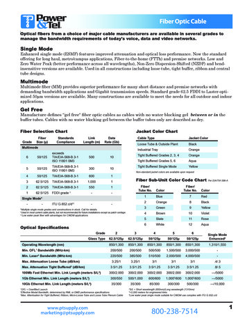
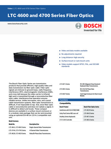
Service Information Sheet for Serial Numbers 79370000Calibration AdjustmentsStep 2: Coarse Calibration AdjustmentRefer to the schematic in Figure 1 and the drawingin Figure 2 for the locations of measurements andcomponents.2-1. Connect the attenuator output to the referencepower meter.NoteFor the remaining calibrationadjustments, use the cable used in step2-1 for connecting the attenuator outputto the reference power meter or the FOM.2-2. Set the attenuator to 0 dBm. Set the1300 nm light source to -10 dBm 0.05 dBm.Record the level shown on the referencepower meter as Pin (power in) for use in step2-6.2-3. Connect the attenuator output to the FOM.2-4. Measure Vdet between U1 pin 7 and theanalog ground reference at U1 Pin 4. AdjustR2 for 0.3 V 0.01 V dc.3-3. Use Pin from step 3-1, Vref from step2-5, and the transfer function below tocalculate Vo:Vref 9R ( ( Pin ) 3 dBm ) 53 dBm 3-4. Measure between DBout at U2 pin 7 and theanalog ground reference at U1 Pin 4. Use theformula below to calculate Vn:Vn DBout - Vo (from step 3 - 3)23-5. Adjust R10 for Vn 0.0005 V at DBout.3-6. Connect the attenuator output to the referencepower meter. Set the attenuator for a powermeter reading of -10 dBm 0.1 dBm.3-7. Connect the attenuator output to the FOM.Adjust R2 for Vo 0.0005 V (as calculated instep 2-6) at DBout.3-8. Repeat steps 3-1 through 3-7 until the FOM’s-10 dBm and -45 dBm readings are withinspecifications.2-5. Measure Vref between U2 pin 1 and theanalog ground reference at U1 Pin 4. Recordthis value for use in the transfer functioncalculations.Step 4: 850 nm Fine CalibrationAdjustment2-6. Use the following transfer function tocalculate Vo:4-1. Set the switch on the FOM to the 850 nmposition.Vref 9R ( ( Pin ) 3 dBm ) 53 dBm 2-7. Measure between DBout at U2 pin 7 and theanalog ground reference at U1 Pin 4. AdjustR10 for Vo (as calculated in step 2-6) 0.0005 V.Step 3: 1300 nm Fine CalibrationAdjustment3-1. Connect the attenuator output to the referencepower meter. Set the attenuator output to-45 dBm 0.1 dBm. Record the value shownon the reference power meter as Pin for step3-3.4-2. Set the 850 nm light source to -10 dBm 0.05 dBm. Use the reference power meter tomeasure the source output power level.Record this level as Pin for use in step 4-4.4-3. Connect the 850 nm light source to the FOM.4-4. Use Pin from step 4-2, Vref from step2-5, and the transfer function below tocalculate Vo:Vref 9R ( ( Pin ) 3 dBm ) 53 dBm 4-5. Measure between DBout at U2 pin 7 and theanalog ground reference at U1 Pin 4. AdjustR1 for Vo (as calculated in step 4-4) 0.0005 V.3-2. Connect the attenuator output to the FOM.5
DSP-FOMFiber Optic MeterStep 5: 1550 nm Fine CalibrationAdjustment5-1. Set the switch on the FOM to the 1550 nmposition.5-2. Set the 1550 nm light source to -10 dBm 0.05 dBm. Use the reference power meter tomeasure the source output power level.Record this level as Pin for use in step 5-4.5-3. Connect the 1550 nm light source to theFOM.5-4. Use Pin from step 5-2, Vref from step2-5, and the transfer function below tocalculate Vo:Vref 9R ( ( Pin ) 3 dBm ) 53 dBm 5-5. Measure between DBout at U2 pin 7 and theanalog ground reference at U1 Pin 4. AdjustR3 for Vo (as calculated in step 5-4) 0.0005 V.Step 6: Verifying Calibration6-1. Follow the procedures given in the earliersection "Performance Tests".6-2. Apply insulating varnish, such as red GLPT,to R1, R2, R3, and R10.6-3. Reassemble the FOM as described in theearlier section "Disassembling andReassembling the FOM".6Parts and AccessoriesReplacement parts (Table 2) and accessories(Table 3) are available from Fluke.Table 2. Fluke Replacement Parts for the DSP-FOMDescriptionFluke PartNumberDSP-FOM Plastic Case Assembly616034Battery Door200474PD1: Germanium Photodiode, 1 mm602778Table 3. Accessories for the DSP-FOMDescriptionFluke PartNumberST to ST Multimode Patch Cable, 1m617453ST to ST Cable Adapter602810Carrying Case616091
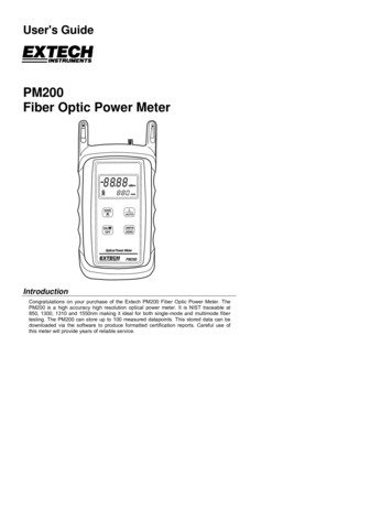
VdetDBoutVrefFPM2-00-0300Service Information Sheet for Serial Numbers 79370000Fiber Optic Meter Schematic for SN 79370000Figure 1. Fiber Optic Meter Schematic for SN 79370000Dt11f.eps7
DSP-FOMFiber Optic MeterPin 7Pin 1Pin 5Pin 7FPM2-00-0001Figure 2. Calibration Measurement and Adjustment Points for SN 793700008Dt14f.eps
4. On the CableMeter test tool, press #Power. Allow a few seconds for the reading to stabilize; then verify that the reading shows the power level recorded in step 2 0.4 dBm. Turn off the test tool, FOM, and the light sources. Disconnect the FOM and 2-meter UTP patch cable from the test tool. Disconnect the fiber optic patch cables from the .
![Fiber Optic - Perimeter Intrusion Detection System [Fopids]](/img/57/foss-presentation.jpg)