Transcription
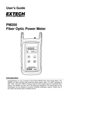
User's GuidePM200Fiber Optic Power MeterIntroductionCongratulations on your purchase of the Extech PM200 Fiber Optic Power Meter. ThePM200 is a high accuracy high resolution optical power meter. It is NIST traceable at850, 1300, 1310 and 1550nm making it ideal for both single-mode and multimode fibertesting. The PM200 can store up to 100 measured datapoints. This stored data can bedownloaded via the software to produce formatted certification reports. Careful use ofthis meter will provide years of reliable service.
Table of ContentsSpecifications3Description4Operation61.0 Applications61.1 Precautions61.1.1 Safety61.1.2 Operational61.2 Required Accessories61.2.1 Cleaning Supplies61.2.2 Patch Cords61.2.3 Optical Fiber Adaptors1.3 Typical Applications671.3.1 Optical Power Measurement1.3.2 Optical Loss Measurement771.4 Optical Power Measurement81.5 Optical Loss Measurement (Set Reference)91.6 Optical Loss Measurement101.7 Data Storage111.8 Downloading Data into PC with Reporter Software121.8.1 Standard Selection131.8.2 Fiber Type Selection141.8.3 Fiber Length Input151.8.4 Connectors and Splices Input161.8.5 Company Selection171.8.6 Name Input181.8.7 Summary View191.8.8 Report Printing191.8.9 Example Printout201.9 Clearing Data212.0 PC Based Meter Control223.0 Battery Replacement234.0 PM200 Data Storage Error Codes23Warranty242PM200 V1.0 11/04
SpecificationsOptical SpecificationsDetector Type Germanium(Ge)Calibrated Wavelengths (nm)850, 1300, 1310, 1550Measurement Range (dBm) 5 to -60Accuracy (dB) 0.15Resolution (dB)0.01General SpecificationsBattery LifeOptical ConnectorData Storage up toDownloadSoftwareDimensionsWeight (with battery)100 hours (9-volt)2.5mm universal100 storage pointsDB-9 serialReporter4.94 x 2.75 x 1.28 in10 ounces3PM200 V1.0 11/04
Meter Description11.Battery Charging Port2.Download Port3.Detector Port4.Tone Mode5.Power Reading6.Battery IndicatorData Indicator.8.Units Indicator9.Wavelength Indicator348567.2-20.28uWmW131010. SAVE / DOWNLOAD button971210131111. ON / OFF / Backlight button12. λ / AUTO button13. UNITS / ZERO button4PM200 V1.0 11/04
1.Battery Charging Port - If rechargeable 9-volt batteries are used in the PM200, thebattery charging port is used to re-charge them when used with an approved walltransformer. NOTE: DO NOT USE BATTERYCHARGING PORT WITH NONRECHARGEABLEBATTERIES. THERE IS THE POTENTIAL FOREXPLOSIONAND DAMAGE MAY OCCUR TO THE UNITAND/OR THE USER.2.Download Port - The download port is used to download stored data into a PC viathe supplied serial cable.3.Detector Port - The detector port is a fixed 2.5mm universal port, and connects toST, SC, or FC connectors equally well without any loss of accuracy. There is noneed to change or maintain expensive adapter caps.4.Tone Mode - When ‘Hz’ is visible on the display, the PM200 is checking for thepresence of a modulated optical signal. These modulated signals are used toautomatically switch wavelengths when they are sent by an OWL light source withmodulation capability.5.Power Reading - The power reading displays the level of optical power beingreceived by the photo detector, and is displayed in either dBm, dB, milliwatts, ormicrowatts.6.Battery Indicator - The battery indicator shows the amount of life is remaining in thebattery. Also, when the battery recharger is in use, the bars in the battery icon areanimated to show that the recharger is active.7.Data Indicator - This icon shows whether there is data stored in the PM200.8.Units Indicator - The units indicator shows which units are being currently displayed.Units are shown in either dBm, dB, uW, or mW.9.Wavelength Indicator - The wavelength indicator shows the currently selectedwavelength in nanometers (nm).10. SAVE / DOWNLOAD button - To store a data point, press this button. Hold thebutton to down load data points in comma-delimited format. This button can also beused to erase all stored data if it is held while the meter is being powered ON.11. ON / OFF / Backlight button - When the unit is off, press this button to power on.When the unit is on, press this button to toggle the backlight on and off. When theunit is on, hold this button to power off.12. λ / AUTO button - Press this button to change wavelengths. Hold this button to setthe meter in AUTO mode. AUTO mode scans incoming power for modulated opticalsignals, and switches wave lengths automatically when a corresponding modulatedsignal is received (for use with WaveSource light sources only.)13. UNITS / ZERO button - Press this button to change display units - either dBm, dB,uW or mW. Holding this button will set a ZERO reference for the currently selectedwavelength.5PM200 V1.0 11/04
Operation1.0 Applications1.1 Precautions1.1.1 Safety - Caution must be exercised when working with optical equipment.Most transmission equipment and light sources use light that is invisible to thehuman eye. High energy light is potentially dangerous, and can cause serious,irreparable damage to the eye. Thus, it is recommended to look into the connectorport of a light source or the end of a fiber.1.1.2 Operational - In order to ensure accurate and reliable readings, it is vitallyimportant to clean ferrules containing optical fibers and optical connector ports. Ifdirt, dust, and oil is allowed to build up inside connector ports, this may scratch thesurface of the photodetector, producing erroneous results. Replace dust caps aftereach use.1.1.3 Operational - In order to ensure accurate and reliable readings, it is vitallyimportant to clean ferrules containing optical fibers and optical connector ports. Ifdirt, dust, and oil is allowed to build up inside connector ports, this may scratch thesurface of the photodetector, producing erroneous results. Replace dust caps aftereach use.1.2 Required Accessories1.2.1 Cleaning Supplies - It is recommended to clean fiber ferrules before eachinsertion with 99% or better isopropyl alcohol and a lint free cloth. A can ofcompressed air should be available to dry off the connector after wiping, and toblow out dust from bulkheads.1.2.2 Patch Cords - Patch cords may be needed to connect the PM200 to thesystem under test. The connector styles on the patch cord must match the type onthe PM200 and the type of the system under test.1.2.3 Optical Fiber Adapters - Optical fiber adapters are used to connect twoconnectorized fibers together, and may be necessary to adapt your patch cords tothe system under test.6PM200 V1.0 11/04
1.3 Typical ApplicationsPM200 test kits can be used as diagnostic and measurement tools of opticaltransmission systems and fiber optic links. These applications can be found in severalindustries, including premise, LAN, CATV, and Telco.Two types of measurements are possible with the PM200 optical power meter: opticalpower and optical loss.1.3.1 Optical Power Measurement - When displaying power in dBm mode, thePM200 will measure the absolute amount of power being received in the 2.5mmUniversal detector port. Absolute power is shown in dBm (decibels referenced to amilliwatt), meaning the power being received by the photodetector is compared to 1milliwatt of optical energy. Optical power measurement is useful for checking theoutput power and/or stability of an optical transmission system or stabilized fiberoptic light sources.1.3.2 Optical Loss Measurement - When displaying power in dB mode, the PM200can be used to measure the optical power through a fiber optic link relative to anoptical reference point. Setting a reference point is also known as “zeroing” themeter with a light source. Optical loss measurements are useful for measuring theattenuation, or loss, of a fiber link. The loss value can then be compared to a precalculated link budget, which is used to determine if the fiber link will operate withinthe parameters of the transmission equipment.The formula for calculating loss in a fiber link is: L P - P a rwhere L is the amount of optical loss in dB, P is the absolute power in dbm, and Pis the reference power in a r dBm.Optical loss measurements can also be used for fiber optic link certification. Linkcertification is a process where optical loss measurements are compared to a linkbudget calculated using fiber optic cabling standards.Data stored in the PM200 can be downloaded into the Reporter certification reportsoftware. Fiber optic links can be certified against one of several popular fiber opticcabling standards or one of two user configurable standards. Many fiber opticinstallation bids are requiring certification reports, which makes the PM200 aninvaluable tool for fiber optic professionals.7PM200 V1.0 11/04
1.4 Optical Power Measurementa)b)c)d)Connect the PM200 to theequipment under test (EUT). In theexample below, the EUT is a fiberoptic light source.Power on the EUT, set it to thedesired wavelength, and allow it tostabilize.Power on the PM200, and set it tomatch the wavelength of the EUT.Set the units to dBm. The resultantreading is the output power. (Theexample in Figure 2 shows anoptical output power of -20.58 dBm).This reading should be within the lightsource manufacturer’s specified powerlevel. If the reading is not within thespecification, clean and check theconnections and take anothermeasurement.-20.58dBm1310 nmPM200Figure 28PM200 V1.0 11/04
1.5 Optical Loss Measurement (Set Reference)Two patch cords are required for this procedure - one for the meter side and one for thelight source side.a)b)c)d)e)f)g)h)Connect the PM200 to a light source using the first patch cord.Power on the light source and allow it to stabilize according to the manufacturer’sspecifications.Power on the PM200, and set it to match the current wavelength of the lightsource.Check to make sure the power level displayed on the PM200 is approximatelyequal to the calibrated power level of the light source (see Figure 2 on the previouspage). If it is good, then remove it from the PM200 and light source and set it aside.This will be the patch cord for the meter side.Connect the other patch cord to thePM200 and light source as shown inFigure 3. The example shows areference setting procedure formultimode light sources. Notice the½” MANDRELinsertion of a 1/2” mandrel. Mandrelsare used to achieve EMD (EquilibriumMode Distribution) when setting thereference from a multimode lightsource. EMD is achieved by wrappingthe reference patch cord around themandrel 5-7 times. Single-modesources do not require a mandrel.0.00 dBPress the λ / AUTO button on the1310 nmPM200 to set it to the desiredwavelength.Set the light source to the match thewavelength on the PM200.Press and hold the UNITS / ZERObutton on the PM200. This will set thereference for the currently selectedwavelength. The display will switch toshow dB units, and should showapproximately 0.00 dB.Figure 3PM200If there is a second wavelength to ‘zero’, repeat steps f through h. The indicator LED willchange colors for the second wavelength.The PM200 is now ‘zeroed’, and is ready to test fiber links.NOTE: DO NOT REMOVE THE PATCH CORD FROM THE LIGHT SOURCE, AS THISWILL MAKE THE OPTICAL REFERENCE INVALID.9PM200 V1.0 11/04
1.6 Optical Loss Measurementa)b)c)Leaving the patch cord attached to the lightsource, remove the patch cord from the PM200optical power meter.Connect the PM200 and light source to oppositeends of the link under test.The PM200 will show the amount of loss in thelink (in dB). Figure 4 shows a power level of -2.45dB. This means that the optical power beingreceived by the meter is 2.45 dB below theoptical reference, which is the same as sayingthere is 2.45 dB of optical loss in the link.Optical loss measurements are compared to a precalculated link budget. If the optical loss does notexceed the link budget calculation, the link willperform as installed within the specificationsshown on the link budget.LINK UNDER TESTPATCH PANELS-2.45dB1310 nmPM200Figure 410PM200 V1.0 11/04
1.7 Data Storagea)b)c)Connect the PM200 and light source to opposite ends of the link under test.Press the SAVE / DOWNLOAD button. The PM200 will store a data point for eachwavelength, and will briefly show the number of data points currently stored inplace of the wavelength. The presence of the data storage icon () shows thatthere is data stored in the meter. From time to time, an error code may appear.These error codes and descriptions are located later in this manual.Connect the units to the next fiber in the link, and repeat step b. Notice the numberof data points will increment by 2 (one data point per wavelength).NOTE: the PM200 can store up to 100 data points. It is highly recommended todownload the stored data periodically using the Reporter software.11PM200 V1.0 11/04
1.8 Downloading Data to a PC With Reporter SoftwareOnce testing is complete or the PM200’s memory is full, the stored data points may bedownloaded to a PC running the Reporter software. A Pentium PC (or better) runningWindows 95 or later operating system is required for Reporter Software. Please use theincluded CD to install the software. Insert the CD to begin the installation. Follow the onscreen steps to install. Once Reporter is installed on the PC, it is ready to download thedata points from the PM200.Connect the PM200 to the PC COM port via the supplied download cable.First, prepare the PM200 for download to PC. Follow the steps below:With the PM200 powered ON, run Reporter. The shortcut is located in the Start Menu,under Programs, Extech, and is named Reporter. There may also be a shortcut on thedesktop.Begin the data download by pressing the download button which is highlighted on thescreen shot at the right. The software automatically downloads all that is stored in themeter. First, the software searches for the meter, then it transfers the data, then gives aconfirmation of download success.If the download fails, communications cannot continue and no data will download into thePC. Check the cable connections, test the current COM port, and/or try a different COMport or try a different PC.The following pages explain the steps of the Link Wizard in Reporter. This will allowcertification of fiber links using a fiber cabling standard.12PM200 V1.0 11/04
1.8.1 - StandardSelection1.8.1.1 - View the list ofcabling standards.The list will appearwhen you click thedown arrow.1.8.1.2 - Select the cablingstandard from thedrop-down list.1.8.1.3 - Once the cablingstandard has beenchosen, thewavelengths andfiber types that thestandard supportsappear in the boxeson the right.Click Next to continue.13PM200 V1.0 11/04
1.8.2 - Fiber TypeSelection1.8.2.1 - View the list ofavailable fiber types.The list will appearwhen the downarrow is clicked.1.8.2.2 - Select the fibertype from the list.The selected fibertype should matchthe type of fiber ofthe link under test.1.8.2.3 - Once the fibertype has beenchosen, it appearsin the dropdownbox.Click Next to continue.14PM200 V1.0 11/04
1.8.3 - Fiber Length Input1.8.3.1 - Enter the lengthof the fiber link under test.This length will apply to allof the data pointsdownloaded from thePM200. Type the length inthe input box, and selectthe length units at theright.1.8.3.2 - Once the fiber linklength and the length unitsare entered.Click Next to continue.15PM200 V1.0 11/04
1.8.4 - Connectors and Splices Input1.8.4.1 - If there areany connections orsplices in the link,enter them into theinput boxes.1.8.4.2 - Once thenumber ofconnections andsplices have beenentered.Click Next tocontinue.16PM200 V1.0 11/04
1.8.5 - Company Selection1.8.5.1 - Select thecompany name from thedrop-down list. If it is notlisted, click the NewOrganization button.1.8.5.2 - Type in theorganization’s name andtelephone number into theinput boxes.1.8.5.3 - Once theorganization’s name andtelephone number havebeen entered, click OK tocontinue.1.8.5.4 - The organizationname should now appearin the dropdown box.Click Next to continue.17PM200 V1.0 11/04
1.8.6 - Name Input1.8.6.1 - Enter adescriptive name forthe link into theinput box.1.8.6.2 - Once thelink name has beenentered, click Finishto continue.18PM200 V1.0 11/04
1.8.7 - Summary ViewBy default,Reporter opensup into DetailView. However,Summary viewmay be moreuseful for fiberloss testevaluation. Toswitch betweenSummary Viewand Detail View,press the buttonthat looks like anarrow, highlightedat the right. Afteryou press thisbutton, the viewwill change tolook like thescreen shot at theright. This screenshows the LinkID, each storeddata point, and whether the test passed or failed.1.8.8 - Report PrintingTo print thecurrent view to aPC printer, pressthe print buttonhighlighted atright to print theSummary report.The printedreport will lookvery much likethe screen. Seean examplereport on the nextpage.19PM200 V1.0 11/04
1.8.9 - Example PrintoutBelow is an example of the Circuit Summary Report. Below are descriptions of thecolumns:Circuit ID - this is the name of the fiber that was testedP/F - shows whether the test passed or failed850nm - shows the amount by which the test passed or failed by at the wavelength tested20PM200 V1.0 11/04
1.9 - Clearing DataAfter data has been downloaded to the PC with the Reporter software, it is recommendedto save the data to a file, and clear the memory from the PM200.To clear data from the PM200, while the unit is OFF, press and hold theSAVE / DOWNLOAD button and press the ON / OFF / Backlight button. Thewill disappear from the display when the data has been successfully erased.21iconPM200 V1.0 11/04
2.0 PC-Based Meter ControlWhen connected to the RS-232 port on a PC using a terminal program (such asHyperterminal), many of the PM200’s functions can be activated from the PC keyboard.The list of functions follows:Key: AFunction: Auto modeDescription: Pressing the ‘A’ key is the equivalent to holding the / AUTO button on thePM200. The wavelength display will begin toggling between the currently selectedwavelength and ‘AUO’. Auto mode scans incoming power for modulated optical signals,and switches wavelengths automatically when a corresponding modulated signal isreceived.Key: CFunction: Clear memoryDescription: Pressing the ‘C’ key is the equivalent to holding the SAVE / DOWNLOADbutton on the PM200 while the unit is powered ON. The data indicator icon will disappearfrom the display.Key: DFunction: Download memoryDescription: Pressing the ‘D’ key is the equivalent to holding the SAVE / DOWNLOADbutton on the PM200. This will download all data into the PC in comma-delimited format.The display will say ‘done’ when the download is complete.Key: MFunction: Monitor modeDescription: Pressing the ‘M’ key will cause the meter to send wavelength and powerlevel information to the serial port. This data will appear in the terminal window. Monitormode is useful for checking the stability and power level of a source over a long period oftime. Most terminal programs have a data capture function. Data captured this way canbe imported as a comma-delimited file into a spreadsheet for creating a chart.Key: UFunction: Units setDescription: Pressing the ‘U’ key is the equivalent to pressing the UNITS / ZERO buttonon the PM200. Each time the ‘U’ key is pressed, the display units will change betweendBm, dB, and uW or mW.Key: WFunction: Wavelength setDescription: Pressing the ‘W’ key is the equivalent to pressing the / AUTO button on thePM200. Each time the ‘W’ key is pressed, the display wavelength will change betweenthe PM200’s calibrated wavelengths.Key: ZFunction: Zero functionDescription: Pressing the ‘Z’ key is the equivalent to holding the UNITS / ZERO buttonon the PM200. Once the PM200 display changes to ‘dB’ units, an optical reference hasbeen set for the currently selected wavelength, otherwise known as ‘zeroed’.Key: ?Function: Firmware version displayDescription: Pressing the ‘?’ button will send the firmware version to the serial port.22PM200 V1.0 11/04
3.0 Battery ReplacementThe battery compartment is covered by a sliding plate on the back of the unit. Removethe rubber boot to expose the back of the unit. One 9v battery is required for operation.4.0 PM200 Data Storage Error CodesERR - the user has not waited long enough to get data stored for both wavelengthsBAD - data can only be stored for a maximum of 3 wavelengthsFUL - memory is full, and no more data can be stored23PM200 V1.0 11/04
WarrantyEXTECH INSTRUMENTS CORPORATION warrants this instrument to be free of defectsin parts and workmanship for one year from date of shipment (a six month limited warrantyapplies to sensors and cables). If it should become necessary to return the instrument forservice during or beyond the warranty period, contact the Customer Service Department at(781) 890-7440 ext. 210 for authorization or visit our website www.extech.com for contactinformation. A Return Authorization (RA) number must be issued before any product isreturned to Extech. The sender is responsible for shipping charges, freight, insurance andproper packaging to prevent damage in transit. This warranty does not apply to defectsresulting from action of the user such as misuse, improper wiring, operation outside ofspecification, improper maintenance or repair, or unauthorized modification. Extechspecifically disclaims any implied warranties or merchantability or fitness for a specificpurpose and will not be liable for any direct, indirect, incidental or consequential damages.Extech's total liability is limited to repair or replacement of the product. The warranty setforth above is inclusive and no other warranty, whether written or oral, is expressed orimplied.Calibration and Repair ServicesExtech offers repair and calibration services for the products we sell. Extech alsoprovides NIST certification for most products. Call the Customer Service Department forinformation on calibration services available for this product. Extech recommends thatannual calibrations be performed to verify meter performance and accuracy.Support line (781) 890-7440Technical support: Extension 200; E-mail: support@extech.comRepair & Returns: Extension 210; E-mail: repair@extech.comProduct specifications subject to change without noticeFor the latest version of this User’s Guide, Software updates, and otherup-to-the-minute product information, visit our website: www.extech.comCopyright 2004 Extech Instruments CorporationAll rights reserved including the right of reproduction in whole or in part in any form.24PM200 V1.0 11/04
Fiber Optic Power Meter Introduction Congratulations on your purchase of the Extech PM200 Fiber Optic Power Meter. The PM200 is a high accuracy high resolution optical power meter. It is NIST traceable at 850, 1300, 1310 and 1550nm making it ideal for both single-mode and multimode fiber testing. The PM200 can store up to 100 measured datapoints.
![Fiber Optic - Perimeter Intrusion Detection System [Fopids]](/img/57/foss-presentation.jpg)