Transcription
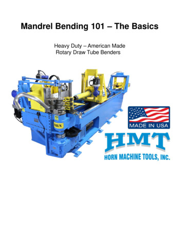
Mandrel Bending 101 – The BasicsHeavy Duty – American MadeRotary Draw Tube Benders
Heavy Duty – American MadeRotary Draw Tube BendersMandrel Bending 101 – The BasicsPresented to:Agenda:Day 1 – Afternoon in Classroom (4 to 5hrs)1) Introduction2) Safety3) Principles of Rotary Draw Mandrel Bending4) All about Tooling & Machines5) SetSet-up practicesDay 2 – Meet in Classroom (1/2hr) and Shop (3.5hrs)1) SetSet-up & Tear down bending machines, troubleshoot problems,identify improvements & create action planDay 2 – Afternoon (4hrs)1) Finish up setset-up in Shop if needed2) Review of Classroom theory as applied to shop work3) New Ideas for quick change setups4) Wrap upPresenter: Kent HornDate:
Rebuilds & ServiceUSA Made BendersExcellentResultsHorn Metric Series“High Capability & Value”Replacement Partswww.hornmachinetools.comTel: 559-431-4131California – Texas – Minnesota - Indiana
SafetySafety Precautions:1) Most common severe injury is from clamp die2) Second most common injury is from Swing Arm & Tube3) Other areas, pressure die, carriage & mandrel4) Strains & injury during set-up5) Two operators – Must have interlock systemAlways:1) Operate machine with systems and guards in place2) Follow Company safety policies3) Use the right tool for the job4) Be aware of machine condition5) Be aware of others in the areaNever:1) Disable a safety device or violate safetyprocedures2) Compromise safety for production efficiency3) Reach into machine operation zone whilecycling4) SET THE MACHINE UP WITH MOTOR “ON”ANSI B11.15 Safety for Tube and Pipe Bending MachinesEnd user is ultimately responsible for safety of operations
Safety VideoWatch safety video on YouTube at:Click here for Safety VideoGo to the Horn Machine Tools YouTube ChannelThe video is under the safety playlist
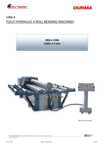
Safety MatsSafety Mat Operation:1) Safety Mats must be secured to floor2) Safety Mats must be connected to a safety rated relay3) Safety Relay must stop all machine motions when activated4) Do not place cardboard on top of mats to hinder operation5) Do not move the mats to allow closer accessSafety Zone:1) Must block access to tooling pinch points2) Must not allow access to area between swing arm and PD Arm3) Used in combination with other point of operation machineguardingSafety zone around bender with safety mats secured to floor
Safety Floor ScannerSafetyScannerSafety Scanner Operation:1) Safety scanner must be secured to floor or machine, cannot move2) Safety scanner must be connected to a safety rated relay3) Safety Relay must stop all machine motions when activated4) Can be programmed for a specific zone shape to accommodate area5) Do re-program the zone area to allow closer accessSafety Zone:1) Must block access to tooling pinch points2) Must not allow access to area between swing arm and PD Arm3) Used in combination with other point of operation machineguardingSafety zone around bender with safety scanner secured to machine
Safety Point of Operation GuardingSafety point of operation guarding CarriageSafety Point of Operation Guarding and signage:1) Safety guards to cover pinch points and areas not covered by mats2) Safety warning labels to alert operators to potential hazards3) Moveable guards and access covers must have electrical interlocks4) Pinch Points, carriage, collet, mandrel, tube support, retractable wipermulti-stack shifting, pressure die, clamp slide, centerline radius motors5) Consider safety cage around bender or on machine guardingSafety point of operation guarding mandrel base
Safety Warning LabelsMust be affixed to machine and warn operators of potential hazards
Mandrel Bending 101“The Basics” MachineBender Type and Condition ToolingDesign and Condition of tools Set-upProper Set-up and Adjustment MaterialMaterial Type and Quality LubricationProper Type and Amount
Tooling TerminologyWiper DieBend DieMandrelPressure DieClamp DieMaster Collet and collet pads
Tooling LocationsPressure DieMandrelColletClamp DieBend DiePicture of HMT 5.0 BenderWiper Die
Bending Machine TerminologyPD ArmClamp DieHolderY Axis BoostMotorOverheadTie BarsMandrelRodMandrelExtractorPressure DieHolderY AxisDistanceDBBC AxisBend ArmDOBDie BossPicture of HMT 5.0 BenderWiper DieHolderB AxisRotatePOBTubeSupport
Principles:Rotary Draw Mandrel BendingDescription:“Tube forming process where the tube isdrawn over a mandrel and formed arounda radius die while supported on allsurfaces ID and OD at the tangent point”
Principles:Rotary Draw Mandrel Bending“Main Concept” A balance of pressuremust be achieved, somaterial can be put into a“plastic” state and allowmaterial to “flow” into thedesired shape without undesired deformation.Representative plastic strain distribution after bending
Principles:Rotary Draw Mandrel Bending“Two Laws”1) The tube must be supported on allsurfaces, ID and OD at tangentduring bending.Tangent Point2) Tube must “Flow” over themandrel.
Principles:Rotary Draw Mandrel Bending1) The tube must be supported on all surfaces, ID andOD at tangent during bending.During bending, the tube isdrawn over the mandrel whilebeing supported on all sides.This process induces highenough pressure to yield thematerialMandrel supports tube on the IDBend Die supports tube on inside radius of tube OD and provides the radius forming sizeWiper Die supports tube on insideradius of Tube ODClamp Die supports tube on outside ofOD and locks tube into bend diePressure Die supports tube on the outsideradius of tube ODIf there is any unsupported area of the tube, the material willflow into that area and cause a defect (bulge – wrinkle, etc).
Principles:Rotary Draw Mandrel Bending2) Tube must “Flow” over the mandrel underthe lowest pressure possible.1 Rake Angle is exaggeratedFor demonstration purposes4231- Wiper die adjusted so pressure of tube compressing is spread out Too much rake angle and more pressure die force is neededMore Pressure die force will increase drag and cause clamp to slip. Not enough rake angle and tube will drag upon entering2 – Adjust mandrel: Far enough forward to eliminate wrinkles andstretch outside of tube correctly. But not so far forward it will causeexcessive drag and break tube3- Adjust the pressure die: Lightest force possible.4 – Adjust Pressure die assist: To push outside of tube over mandrelAnything that causes drag or resistance in the bend processwill hinder the flow of material over the mandrel.
Principles:Tube Forming Process Results1)2)3)4)5)Inside wall of tube thickensOutside wall of tube thinsThe tube goes into a oval shape in the bend areaThe tube elongatesThe tube springs back after bending when clamp opens
Principles:Tube Forming Process ResultsWall Thinning and OvalityWall ThinningThe outside radius wall thins as it is drawn over the mandrelOvalityThe tube is collapsed to an oval conditionOvalityInside wall thickensDistortion of the natural axisAs shown by the weld seamOutside thins out – Wall ThinningNormal Wall Thinning 8-30%Normal Ovality 5-20%
Principles:Tube Forming Process ResultsTube Thickens onInside radiusTube Thins onOutside radius
Principles:Tube Forming Process ResultsElongationTube Thickens onInside radius andgrows in lengthEffect of draw bending over a mandrelIs elongation of the tubeTube Thins on outsideradius and pulls back
Principles:Wrap up of bending principlesRule #1Tube must be contained on all sides at point of tangentRule #2Tube must flow over the mandrel with minimum pressureAlmost every problem with bending will goback to one or both of these rules
Principles:Material PropertiesCarbon Steel AluminizedYieldTensileElongation33 ksi49 ksi41%YieldTensileElongation35 ksi85 ksi55%Stainless Steel 304Typically between 8% - 12% Nickel contentStainless Steel 409YieldTensileElongation39 ksi68 ksi30%Typically less than 5% Nickel contentNotes:Ksi: 1,000 pounds per sq/in force (33,000 lbs/sq in)Yield: Amount of force needed to form materialTensile: Amount of force needed to break material (pull apart)Elongation: Stretch-ability factor, higher the number the betterNickel Content in Stainless material:5% or less, difficult to form on tight radius8% to 12%, deep draw material very formable on tight radius12% to 15%, ultra deep draw material, extremely good formingproperties on tight radius at very thin wall
Tooling – Bend Die TypesSpool DieMulti-Stack DiesFlange StyleOne PiecePartial Platform
Tooling – Bend Die BasicsBend die with square block insertThru HoleClearance to die bossStud should be .031”For ease of installKeywayFit: .003” to .005”Centering pocketCenterline RadiusFit: .003” to .005”Die must be concentricwhen rotatedThis is the distance fromthe center of the radiusto the center of the tubeCenterline Height3” machine 2” CLH6” machine 3.75” CLHBest for difficult applicationsMost economicalInterlock for Clampand PDBend die with concentricbore insertNon-InterlockBend dieOne piece bend die withno insert
Tooling – Bend Die InsertsTypical spool type bend die with flat back type insert, standard design, economical to make Insert should be securely mounted to bend die No mismatch to bend die groove, or marking will occur No misalignment to bend die or clamping problems will occur When clamping surface deteriorates, replace insert if slipping Insert can become fish-mouthed and slipPremium type concentric bore insert, best for difficult applications,advanced design, expensive to make
Tooling – Bend Die Mounting4152361)2)3)4)Die boss should be clean, flat & levelKey should be straight, square & fit die .003” to .005”Centering ring should be concentric & fit die .002” to .003”Die boss stud should be perpendicular to die boss, not bent.Should be tightly screwed into bend head5) Die boss nut should be tightly secured so bend die does not tilt6) Groove should be in good condition or poor bend quality willresult, along with accelerated wear of the wiper dieProperly mounted bend die should be stable and nottilt or deflect when clamp or pressure die closes
Tooling – Clamp DieClamp DieClamp DieMounting KeyClamp Die ForceClamp die length, rule of thumb:2 x OD with serrated grips1.5 x OD with boosted carriage & serrated gripsClamp die locks the tube into the bend die and preventsthe tube from slipping during forming.If tube slips, then bend defects such as marking andwrinkling will occur.Before adding more force to reduce slippage, alwayscheck set-up for excessive drag first.
Tooling – Clamp Die SetupStrive for optimum clamp length and grip surface combination.The more aggressive the grip surface, the shorter the clamplength can be. Typical clamp length is 2 times the OD of tube.Clamp Die shown interlocked with Bend Die.Adjust the height of clamp dieTo match bend die carefully orDamage to surface will occurAlignment of tube groovein all directionsGap top and bottomShould be equal.025” - .050” typicalSet-up Notes: Alignment of clamp die and bend die tube grooves. Squareness of clamp die to bend die, top to bottom, side to side. Must have a gap between the dies, not bottomed out. Correct force applied to hold the tube from slipping. No excessive force applied that will cause bend die tilt or clampedthru mandrelOnly use enough clamp force to hold the tube in the bend die andKeep it from slipping
Tooling – All Electric Clamp DieCutaway view of ALL Electric CNC Bender with Direct Clamp DieAutomatic set-up, no wrenches neededThe HMT All Electric direct acting Clamp Die uses an inline rollerscrew to create a specific amount of force on the tube at alltimes.The all electric direct clamp die automatically finds the correctposition. It’s ideal for repeating set-ups without the use ofadjusting a jam bolt, force can be programmed or set in thecontrol then repeated with every set up.The HMT All Electric Clamp die is guided by 4 linear rails and 8linear bearings. This system provides an extremely rigid clampingsystem and is the best system available.
Tooling – Clamp Die HolderT-Slot MountClamp DieClamp Die HolderBack up BarHolds clamp die in position locks tube into bend die.Mounting with T-Slot or half round post to keep clamp die alignedsquare with bend die.Holder has lock down bolts and some type of back up bar or methodto keep holder from backing up.The tube can not slip in the bend die grip
Tooling – Drop Away ClampPrinciple of operationPicture of clamp toggle linkage* Clamp toggle linkage creates a mechanical advantage and producesmuch more force than hydraulic cylinder alone.* Cylinder must extend far enough to take linkage over center and“lock” in place.* If not locked in place over center then possible that hydrauliccylinder will loose pressure during the bend cycle and back offcausing clamp slippageClamp ClosedClamp OpenUse a straight edge to makesure toggle links are overcenter.Avg amount is 1/16” to 1/8”
Tooling – Drop Away ClampSetup and AdjustmentWith Bend Die Mounted & tube in place1) Back up clamp holder to clearance position2) Install clamp Die3) Start machine and close clamp4) Position holder to contact tube & adjust height5) Tighten jack screw to obtain correct clamping pressure6) Tighten bolts on clamp holderJack ScrewPicture of jack screw Jack screw backs up the clamp holder andkeeps holder from sliding back and loosing position. Subjective set up: It is possible to use a quarter turnmethod to determine how much pressure is beingapplied to clamp. Example: Tighten up jack screwto closed die position, then go ¼ turn, try bend,if slippage then tighten another ¼ turn.Positive set-up:Use a torque wrench!
Tooling – Direct Acting Clamp DiePicture of Direct acting Clamp DieDirect acting Clamp Die uses a hydraulic cylinder to create aspecific amount of force on the tube at all times.The direct clamp die is ideal for repeating set-ups without the useOf adjusting a jam bolt, pressure can be programmed or set incontrol.NOTE: The cylinder MUST NOT be positioned so it will bottomout during the bend. There should be 1/8” to ¼” of travel left oncylinder when clamp is closed
Tooling – Pressure DiePressure Die Assist ForcePressure DiePressure Die Close ForcePressure Die:Holds tube in bend die grooveSupports the tube on the outside of the radiusHelps push the outside of the tube over themandrel – PDA (Pressure Die Assist)Pressure die min length MAL 2xDMax arc length 2 times tube OD (may use less 1.5)MAL Formula : CLR x 2 x 3.14 / 360 in/per degree , thenIn/per degree x max bend angle MALExample 2” OD x 4” CLR4 x 2 x 3.14/360 .0697” In/per degree x 90 6.279” MAL6.279” 4” 10.279” or 10” long pressure die
Tooling – Pressure Die SetupAdjust height of pressure die for properAlignment with bend die. Use caution orDamage to die surface will occurKeyway fit .003”If marking is presenton bend die interlockThen pressure dieis bottoming outGap top and bottomShould be equalTypical .025” Create a balance of pressure between the wiper die and pressure die Setup PD so minimum pressure is used to form tube, this willreduce drag and clamp slip. If pressure die groove is worn, then slip will occur. Slippage on PD reduces the “sticktion” or ability of the PD to pushthe outside of the tube over mandrel
Tooling – ALL ElectricPressure DieThe HMT all electric pressure die arrangement uses a specificamount of force from a roller screw directly where it’s needed tokeep the tube captured into the bend die groove.the force is set through the control and is repeated on every setup.312One of the features of a direct acting pressure die is that itallows the roller to “float” a constant pressure on the tubeduring bending. This allows for minor non-concentric movementOf the bend die to be absorbed. As well, when the tube goes into aslightly oval shape during bending the pressure die can move ina small amount and still maintain a constant force.1) Gearbox and roller screw inline with center of tool stack2) Linear guiding rails on bottom of pressure die3) Top linear guiding rail, a unique HMT feature for ultimate rigidity
Tooling – Pressure Die HolderPressure die holder aligns and positions the pressure die sotube is supported under pressure and allows the pressure dieto move forward during the bend.Direct acting pressure die uses a hydraulic cylinder to create a specific amount offorce on the tube at all times. As tube starts to form and ovality occurs, the pressuredie must be able to move in and keep the same amount of pressure on the tubeThe pressure die is mounted on the follower bar with hanger brackets and is heldin place by a drive key. The pressure die should be level to the bend die and heightadjust so tube groove isaligned.
Tooling – Direct ActingPressure DieA direct acting pressure die arrangement uses a specific amountof force from a hydraulic cylinder to keep the captured into theBend die groove. The force is set by a pressure control valve fromThe hydraulic system. It is either set manually or programmedthrough the control.One of the features of a direct acting pressure die is that theHydraulic cylinder “floats” a constant pressure on the tubeDuring bending. This allows for minor non-concentric movementOf the die to be absorbed.As well, when the tube goes into a slightly oval shape duringThe pressure die can move in slightly and still maintain aconstant force.
Tooling – Set-upDirect Acting Pressure DieWhen setting up a direct acting pressure die, always insure thatThere is at least 1/8” to ¼” of travel left at the end of stroke onThe hydraulic cylinder.This will allow the pressure die to move forward slightly andcompensate for ovality. Never bottom out the pressure die cylinder Adjust the force to minimum pressure needed to make the bend
Tooling – Toggle ActingPressure DieA toggle acting pressure die acts much the same as a toggleacting clamp die. It uses hydraulic force to drive a mechanicallinkage over center and locks in place. The pressure die force isadjusted by the jack screw on the end of the slideEnd view of PD armJack screw adjusts pressureView of toggle linksToggle links must beslightly over centerby 1/16” – 1/8” inorder to lock in placeClose the PD slide, then use astraight edge to check togglesFor correct over-center position.Adjust cylinder clevis if needed.
Tooling – ALL ElectricPressure Die AssistThe HMT ALL Electric pressure die assist automatically matches thePDA speed to the bend die rotation as it moves forward.The speed is set through the control. It allows the operator to matchspeed at 100%, or advance forward slightly to 102% or 105%,thereby pushing the tube forward during the bend. As well if neededthe PDA speed can be retarded to 98% or 95% to stretch the tube.HMT ALL Electric PDA – Automatic setup and followingThe HMT ALL Electric PDA can mount two pressure dies atone time. This can be used for two different sizes or differentlengths. This design is also required to roll form and draw bendon the same part.The design incorporates automatic up/down movement of thePD so that both true multi-radius and multi-stack bending canbe accomplished. Note: machines with one common PDAFollower bar cannot do this.
Tooling – Pressure Die AssistPressure die travel speed must match bend die, or slightly pushingforward.To determine speed, mark the tube at the back of the pressure die.Then make a bend and check relationship.Two common ways to control pressure die assist:SpeedTurn pressure up and use flow control to match speed of bend diePressureOpen up flow control and use pressure setting to push on tubeWithout exceeding position.Third possibility: Automatic servo following by control system
Tooling – Mandrels
Tooling – ALL ElectricMandrel SystemRotating mandrelrod bearingsystemLinear rails guide themandrel rod and preventdamage to the system.Driven by electric servomotor and gearbox whichprovide precise positioning.The HMT All Electric mandrel system allows the operator to setthe position of the mandrel from the control. Then this positioncan be repeated on every setup.
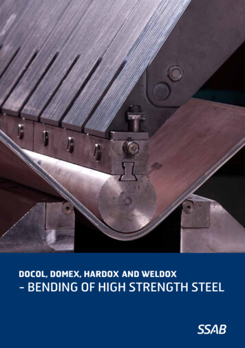
Tooling – MandrelsPlug type mandrel,for easy bendingapplicationsAluminum Bronze mandrelFor bending stainless andOther alloy materialsNote single ball mandrel,With normal pitchHard chrome steel mandrelFor bending carbon steel orNon-ferrous materials.Note 4 ball mandrel, withClose pitch.Mandrel:Supports tube on the ID to keep it from colapsingFroms tube to correct radius on outside of radius
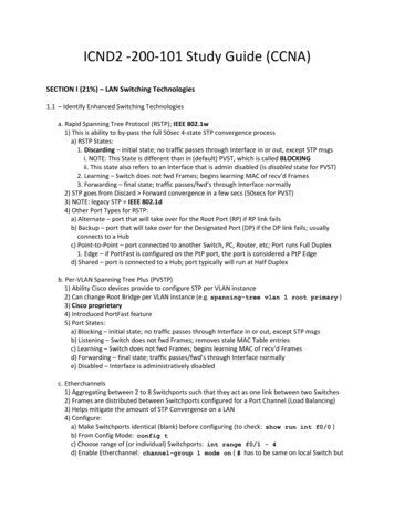
Tooling – Mandrel Components127435861)2)3)4)5)6)7)8)Retainer boltShankBall stackMandrel LinkBall LinkRetainer ClipSpring & ballBall Stack Assembly
Tooling – Mandrel AssemblyNote on Mandrel Ball Stack assembly:It is common for the ball diameter to be smaller than the shank, thisgives the balls additional clearance and keeps from breaking links.For tight radius bending, the balls may be sized differently. Theymay get smaller as they progress from shank, so the end ball issmaller OD than the first ball. Measure balls before assembly tomake sure they are correct for the shank being used.
Tooling – MandrelBallsWork ShoulderLube PortShankMandrel Working Points: The work should is adjusted approximately at Tangent All of the forming work is done on shoulder Shank supports tube behind tangent to prevent collapse Balls keep tube collapsing after bending Balls add drag into the forming process, use few aspossible to achieve a quality bendMandrel Sizing:General rule of thumb is mandrel clearance should be 25% oftube wall thickness. This applies to a 1-1/2 or 2 x D bend.For tighter radius bends, clearance will be less.Example: .065” wall material on 2 x D bend.065 x .25 .016” overall clearance
Tooling – Mandrel SetupPicture of mandrel adjusted at tangentMandrel:In proper position, should strech outside of tube to correctradius which helps to control springback and ovality.If too far back, results will be: More ovality, bend will have flat or collapsed appearance. Wrinkles, not supporting tube correctly on inside Higher springback, outside radius not formed correctlyIf too far forward, results will be: Excessive wall thinning on outside radius Tube breakage Mandrel hump at end of bend (Use early withdrawal) Excessive wear on mandrel shoulder Shuttering or chatter during bend (poor lubrication can also cause this)Note: Mandrel must be locked into position so that tube rotationscan’t cause the mandrel or rod to turn and loose position.For tubes that fight tightly on mandrel, use rotating mandrel rod
Tooling – Mandrel SetupPicture of mandrel adjusted ahead of tangentMandrel forward, low pressure:Position mandrel shoulder forward of tangent which willstrech outside of tube to correct radius with lowest amountof pressure die force.Challenges: Must have a control system capable of early mandrel extract. Some hydraulic machines have a difficult time extracting mandrelearly while bend arm is moving fast Some hydraulic systems will react differently when fluid is cold orhot. This will vary the early withdrawal extract position as machineheats up Tube breakage In consistent mandrel hump at end of bend Excessive wear on mandrel shoulder
Tooling – Wiper Die holderMulti-Stack wiper holderMulti-Stack wiper holderExploded viewThe HMT multi-stack wiper design allows for independentadjustment is each direction.This wiper die system can be used as a cartridge type systemWhereby multiple wiper holders can used to permanently setup the wipers, then the entire holder can be changed out as aunit.
Tooling – Wiper DiesInserted Wiper tip and holderVarious square back WipersAluminum Bronze wiper for bending stainless and other alloy materialsHard chrome steel wiper for bending carbon steel or non-ferrous materials.Wiper die:Supports tube on the inside of radius, behind tangentWorks in conjunction with pressure die to apply balancedpressure on the OD of tube entering the bend die.Hardest die to set and align
Tooling – Wiper Die TypesInsert type wiper die tips Replacement cost is lower Replacement time is quicker Initial investment higher (Holders) Allows close tangent positioning byCNC bender collet May not be suitable for some difficultapplicationsSquare back type wiper May be re-sharpened(30% of new cost) Works well for difficult set-ups Easier to set up more surfacearea Longer tangent positioning lengthby CNC bender collet No special holder required, fits allbenders.
Tooling – Wiper Die Set-upSeatingWiper die must beable to absorb forceand transfer it tobend die.The wiper die must beproperly positioned andseated so the force canbe transferred withoutdamaging wiper die orcausing it to deflect andloose containment.Note: Too muchlubrication on face ofwiper will causewrinkles.12Clamp and pressure die, apply force to out side of tubeThat force is transferred onto the face of the wiperThen from backside of wiper to bend die
Tooling – Wiper Die Set-upSeatingApproximately 25-30 degree of the back side of the wiper must be seated onbend die. Shown above with tool makers die wiped off by bend die.At least .75 to 1 x tube ODseated on the front side of wiperExample:2” OD tube 1.5” to 2.0” seated
Tooling – Wiper Die Set-upTrim to fitIn the picture below, a new wiper die is shown on the left. On the right awiper die that has been installed and then just a few bends made. Youcan see that during the first few bends, the tip gets broken off. This isbecause most wipers are made with the tip too thin. In the last few slides,we talked about seating a wiper properly in order to absorb to PD force.Problem is once the wiper is seated properly, it then its far enoughforward to have the tip broken off.Prevent the tip of thewiper from breaking offprematurely by trimmingand fitting the wiperto the bend die.In order to prevent the wiper tip from being broken off, some wipersCan be trimmed slightly and shaped. This will allow full contactSeating of the wiper but also keep the tip back far enough to preventIt from being damaged prematurely. Call HMT to find out more.This wiper has been trimmed by oneOf our expert techs. Notice how theTip blends into the bend die.After several bends, little or noDamage has occurred.
Tooling – Wiper Die Set-upTip position to tangentTip too far forward will break off sections and cause premature wear.Ideal position for wiper tip is directly behind tangent.Bending forces should be on bend die, not wiper tipWiper tip should be feathered in to support tube directly behindtangent.Note: Wiper must be locked into position so that bendingforce or Pressure Die force does not move the wiper out ofposition
Tooling – Wiper Die Set-upTip position to tangentTip too far back.Tip too far back reduces seating area.Possibility of bending wiper and causing concave area behindtangent.Note: Wiper must be locked into position so that bendingforce or Pressure Die force does not move the wiper out ofposition
Tooling – Wiper Die Set-upTip position to tangentTip in correct locationNote: Wiper must be locked into position so that bendingforce or Pressure Die force does not move the wiper out ofposition
Tooling – Wiper Die Set-upRake Angle PositionThe wiper needs to sit at a slight angle to the pressure die.As radius of bend decreases, so will wiper angle.If wiper position is too flat, or negitive angle, then tube willdrag upon entering wiper die.Negitive rake will also cause a gap and containment will beLost allowing wrinkle to form
Tooling – Wiper Die Set-upHow To Position Wiper dieSlide wiper forward until seated and tip is slightly behind tangent.Rotate wiper die back 1/10th to ¼ degree back to obtain rake angle
Tooling – Wiper Die Set-upHow To Repeat Wiper DiePositionUse caliper to record position of wiper die once set-up is correct.Use straight edge and wire gauge to check Rake AngleNote: Too much lubrication on face of wiper will cause wrinkles.
ColletsFlange styleBolt in collet padsCollet pads boltInto the face ofthe master collet3-5 minuteChange outtimeHMT Quick ChangeSnap in collet padsSeveral types, most use amechanical feature toretain collet pads5 secChangeout timeNote: Collet should be adjusted tight enough to keep tube fromRotating in collet and loosing orientation. But not so tight that it isreducing the end of tube making it difficult to remove off mandrelSome machines have mechanical adjustment, some have pressurevalve adjustment
Carriage BoostY axis carriage booster functional description:Mandrel bending tight radius tubes with a short clamp length is greatly improved byapplying force to the back of the tube as it enters the back of the bend die.This does several things:1) Keeps material flowing over the mandrel and reduces drag in the draw process.2) Because drag is reduced there is less requirement for clamp area,so clamp lengths can be shorter.3) Reduces wall thinning and ovality of the tube.4) Reduces the effect of marking with short clamp grips that are serrated.Pressure die assist can only add a minimal amount for force to the bend beforeslipping forward, with Y axis boost, the tube is shouldered into the collet.The amount of force can be applied up to the column strength of the tube or up to themaximum of rating of machineDifficult Application Set-ups:Boost at high force for first 30 to 45 degrees, then start backing off boost force astube becomes wrapped around the die.Note: Too much carriage boost will cause wrinkles.
HMT ALL ElectricCarriage Boost DesignThe Fastest, most powerful and accurate system available.Bullet proof from crashes!The HMT design uses dual helical gear racks to drive the carriage. Thissystem provides fast positioning that is both accurate and powerful.The system is designed with the gear rack incased within the frame andorientated facing down. This protects the gear rack from debris and alsoKeeps the gear rack out of the way from operators.The dual gear rack, is positioned on both sides of the carriage to distributeforce evenly. The racks are also positioned a
2) Key should be straight, square & fit die .003” to .005” 3) Centering ring should be concentric & fit die .002” to .003” 4) Die boss stud should be perpendicular to die boss, not bent. Should be tightly screwed into bend head 5) Die boss nut should be tightly secured so