Transcription
Testing and Evaluation of Grounding Systems:The Revision of the IEEE Std 81Sakis MeliopoulosGeorgia Power Distinguished ProfessorSchool of Electrical and Computer Engineering,Georgia Institute of Technology,Atlanta, Georgia 30332-0250,Telephone: 404 894-2926, Fax: 404 894-4641Email: sakis.m@gatech.edu or sakis@comcast.netIEEE Industry Applications Society – Atlanta ChapterJanuary 19, 2010 Meeting1
Grounding Purposeand BondingFundamental for a SafeofisGroundingand Reliable Power SystemLightning and Surge ProtectionStabilize Circuit Potential and Assist in Proper Operation of:- Communications- Relaying- Computers & Sensitive Electronic EquipmentLow Fault Circuit Path ImpedanceSafety, Safety, SafetyImprove Quality of Power ServiceIEEE Industry Applications Society – Atlanta ChapterJanuary 19, 2010 Meeting2
Grounding, Bonding and Power Quality“Recent studies indicate that as much as 80% of all failures of sensitiveelectronic equipment attributed to poor power quality may result frominadequate electrical grounding or wiring on the customer’s premises orfrom interactions with other loads within the premises.”Wiring and Grounding for Power QualityEPRI CU-2026, March 1990“However, many power quality problems that occur within customerfacilities are related to wiring and grounding practices. Up to 80% of allpower quality problems reported by customers are related to wiring andgrounding problems within a facility.”Power Quality Assessment ProcedureEPRI CU-7529, December 1991IEEE Industry Applications Society – Atlanta ChapterJanuary 19, 2010 Meeting3
Over the Years Grounding Design Procedures Have Been Developedas Well as Appropriate Standards, Most Notable:Terms and Definitions ANSI/IEEE Std 80-2000, IEEE Guide for Safety in AC Substation Grounding. IEEE Std 487-2007, Recommended Practice for the Protection of Wire-Line Communication FacilitiesServing Electric Supply Locations. IEEE Std 998-1996, IEEE Guide for Direct Lightning Stroke Shielding of Substations. IEEE Std 1410-2004, IEEE Guide for Improving the Lightning Performance of Electric Power OverheadDistribution Lines. IEEE Std 1243-1997, IEEE Guide for Improving the Lightning Performance of Transmission Lines. National Electrical Code. National Electrical Safety Code. FIPS 94 and Derivatives.For the Purpose of Verifying Designs, Testing Procedures have Been alsoDeveloped. Most Notable: ANSI/IEEE Std 81-1983, IEEE Guide for Measuring Earth Resistivity, Ground Impedance and EarthSurface Potentials of a Ground System. ANSI/IEEE Std 81.2-1991, IEEE Guide for Measurement of Impedance and Safety Characteristics of Large,Extended or Interconnected Grounding Systems.IEEE Industry Applications Society – Atlanta ChapterJanuary 19, 2010 Meeting4
The History of IEEE Std 80IEEE Industry Applications Society – Atlanta ChapterJanuary 19, 2010 Meeting5
The History of IEEE Std 80IEEE Industry Applications Society – Atlanta ChapterJanuary 19, 2010 Meeting6
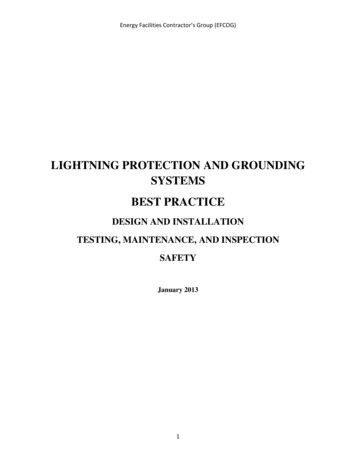
Basis of Standards: IEEE 80 & IECNon-Fibrillating Body Current as a Function of Shock DurationIEEE Industry Applications Society – Atlanta ChapterJanuary 19, 2010 Meeting7
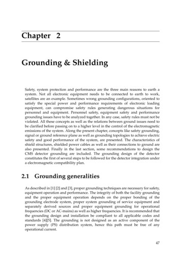
IEEE Std 80, 1986 Edition200100pigssheep300Kiselev DogsDogsFerris DogsFibrillating Current (mA RMS)calvesValue of Constant k for EffectiveRMS Values of IB:k I b tsMinimumFibrillatingCurrent (0.5%)k50 0.116 (Non-Fibrillating, 0.5%)k50 0.185 (Fibrillating, 0.5%)k70 0.157 (Non-Fibrillating, 0.5%)MaximumNon-FibrillatingCurrent (0.5%)k70 0.263 (Fibrillating, 0.5%)0020406080Body Weight (kg)IEEE Industry Applications Society – Atlanta ChapterJanuary 19, 2010 Meeting1008
Earth Current, Ground Potential Rise, Touch & StepBasic Problems:1. Determination of Soil Resistivities2. Computation of Ground Potential Rise3. Computation of Surface Voltages (touch and step)4. Safety Assessment I fault I shield I neutral I earth I counterpoise GPR Rmat I earthIEEE Industry Applications Society – Atlanta ChapterJanuary 19, 2010 Meeting9
Verification - MeasurementsKey Fact:Target Values Must beDetermined in Design PhaseIEEE Industry Applications Society – Atlanta ChapterJanuary 19, 2010 Meeting10
The History of the IEEE Std 81First Edition:IEEE Std 81 – 1962Revision:ANSI/IEEE Std 81-1983IEEE Guide for Measuring Earth Resistivity, Ground Impedance, and Earth Surface Potentials of a Ground SystemTo Address Issues Related to Large Grounding Systems or Systems in Congested Areas:IEEE Std 81.2-1991IEEE Guide for Measurement of Impedance and Safety Characteristics of Large, Extended or Interconnected GroundingSystemsAll of Above Standards were sponsored by:Power System Instrumentation and Measurement CommitteeOf theIEEE Power Engineering SocietyIn the period 2003-2004, I served as the Chair of the Substations Committee of the IEEE Power Engineering Society. Iinitiated and succeeded in transferring sponsorship of the standard to the Substations Committee with the plan to combine thetwo standards into one single standard. The unified standard has been developed in committee (working group E6, Chaired byDennis DeCosta) and we expect to ballot it within the next 12 months.IEEE Industry Applications Society – Atlanta ChapterJanuary 19, 2010 Meeting11
ANSI/IEEE Std 81-1983IEEE Guide for Measuring EarthResistivity, Ground Impedance, andEarth Surface Potentials of a GroundSystem1.2.3.4.5.6.PurposeScopeObjectives of TestsDefinitions.Safety Precautions While Making Ground TestsGeneral Considerations of the Problems Related to Measurements6.1 Complexities6.2 Test Electrodes6.3 Stray Direct Currents6.4 Stray Alternating Currents6.5 Reactive Component of Impedance of a Large Grounding SystemCoupling Between Test Leads6.7 Buried Metallic Objects6.67. Earth Resistivity8. Ground Impedance8.1 General8.2 Methods of Measuring Ground Impedance8.3 Testing the Integrity of the Ground Grid8.4 Instrumentation9. Earth Potential9.1 Equipotential Lines9.2 Potential Contour Surveys9.3 Step and Touch Voltages10. Transient Impedance11. Model Tests12. Instrumentation13. Practical Aspects of MeasurementsAnnex A Nonuniform SoilsAnnex B Determination of an Earth ModelAnnex C Theory of the Fall of Potential MethodAnnex D BibliographyIEEE Industry Applications Society – Atlanta ChapterJanuary 19, 2010 Meeting12
IEEE Std 81.2-1991IEEE Guide for Measurement ofImpedance and Safety Characteristics ofLarge, Extended or InterconnectedGrounding Systems1. Purpose2. Scope3. References4. Safety Practices5. Factors Effecting Grounding System Measurements6. Preliminary Planning and Procedures7. Earth-Return Mutual Effects When Measuring Grounding-System Impedance7.1 Introduction7.2 Measurement Error Due to Earth Mutual Resistances7.3 Measurement Error Due to AC Mutual Coupling7.4 Mutual Coupling to Potential Lead From Extended Ground ConductorsIt was developedto address thespecial problemsand issuesassociated withtesting largeinterconnectedgroundingsystems8. Measurement of Low-Impedance Grounding Systems by Test-Current Injection8.1 Introduction8.2 Signal Generator and Power Amplifier Source8.3 Portable Power-Generator Source8.4 Power System Low-Voltage Source9. Measurement of Low-Impedance Grounding Systems by Power System Staged Faults10. Current Distribution in Extended Grounding Systems10.1 Introduction10.2 Test Considerations10.3 Analysis of Current Distribution in a Grounding System10.4 Induced Current in the Angled Overhead Ground Wire10.5 Current Distribution During a Staged Fault Test11. Transfer Impedances to Communication or Control Cables12. Step, Touch, and Voltage-Profile Measurements13. Instrumentation Components13.5 Fast Fourier Transform Analyzer13.6 Sine Wave Network Analyzer13.7 Staged Fault13.11 Low-Power Random Noise Source13.14 Pulse Generator13.15 Current Transformer (CT)13.16 Resistive Shunt13.17 Inductive Current Pickup13.18 Hall-Effect Probe14. Instrument Performance Parameters15. BibliographyIEEE Industry Applications Society – Atlanta ChapterJanuary 19, 2010 Meeting13
Present RevisionIEEE Std 81-XXXXGuide for Measuring Earth Resistivity,Ground Impedance, and Earth SurfacePotentials of a Ground System1. Overview1.1 Purpose1.2 Scope2. References3. Definitions4. Test Objectives5. Safety Precautions While Making Ground Tests5.1 Station Ground Tests5.2 Special Considerations6. General Considerations on the Problems Related to Measurement7. Earth Resistivity7.1 General7.2 Methods of Measuring Earth Resistivity7.3 Interpretation of Measurements7.4 Guidance on performing field measurements8. Ground Impedance9. Testing Local Potential Differences10. Integrity of Grounding Systems11. Current Splits12. Transient Impedance of Grounding System13. OtherANNEX A (INFORMATIVE) SURFACE MATERIAL RESISTIVITYANNEX B - INSTRUMENTATIONB.1. Megohm MeterB.2. Clamp-On Ground TesterB.3. Smart Ground MeterB.4. Transient Impedance MeterIEEE Industry Applications Society – Atlanta ChapterJanuary 19, 2010 Meeting14
Grounding System Measurements Ground Impedance Measurement MethodsThe 2-Point MethodThe 3-Point MethodThe Fall of Potential MethodThe 62% RuleThe Ratio MethodThe Tag Slope MethodThe Intersecting Curve MethodStaged Fault TestsDriving Point ImpedanceThe SGM Method Continuity/Integrity Testing Soil Resistivity Measurements Touch and Step Voltages Other Tests (Tower/Pole Ground, Transfer V.)IEEE Industry Applications Society – Atlanta ChapterJanuary 19, 2010 Meeting15
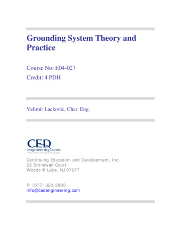
Four Point – Wenner MethodCurrentMeterSourceVoltMeterEarth Surfacelaaaρh1ρ2VR IIEEE Industry Applications Society – Atlanta ChapterJanuary 19, 2010 Meetingρ 4π aR2a1 2 2a 4l 2π a Ra2a l216
Limitations of the Wenner MethodCurrentMeterSourceVoltMeterEarth Surfacelaaahρ1ρ2Vm RI re aI jxe aIρVm rea jxe a2πaIExample: Soil of 10 Ohm.meter, separation 300 feet, measurements at 150 Hz.Compute errorIEEE Industry Applications Society – Atlanta ChapterJanuary 19, 2010 Meeting17
Basic PrinciplesBasic ArrangementVRg IIEEE Industry Applications Society – Atlanta ChapterJanuary 19, 2010 Meeting18
The Fall of Potential MethodThe “62%” RuleIEEE Industry Applications Society – Atlanta ChapterJanuary 19, 2010 Meeting19
Optimal Voltage Probe Location – The 62% RuleIρVa 2πRa 1 1 a D IρVp 2πVa V pρ 1 1 11 2π a D r D r I IEEE Industry Applications Society – Atlanta ChapterJanuary 19, 2010 Meeting1 1 r D r 20
Optimal Voltage Probe Location – The 62% RuleCompareVaρRg I2πaRa Va V pIRa Rg requires that:Solving for r/D yields:IEEE Industry Applications Society – Atlanta ChapterJanuary 19, 2010 Meeting 1 ρ 1 1 1 2π a D r D r 1 11 0D r D rr 1 5 0.618034D221
The Fall of Potential Method – 62% Rule and Two Layer SoilDxρ1hρ2ρ 2 ρ1K ρ 2 ρ1IEEE Industry Applications Society – Atlanta ChapterJanuary 19, 2010 Meeting22
Ground Impedance MeasurementsThe Fall of Potential Method – Measurement ProcessTHEORYCurrent pparent ResistanceGroundUnderTestFlat Curve PortionTrue Ground ResistanceDistance from Ground Under TestIEEE Industry Applications Society – Atlanta ChapterJanuary 19, 2010 Meeting23
The Fall of Potential MethodEarth Voltage Distribution - Actual MeasurementsContributor: American Electric Power1.4Resistance e (feet)276 x 276 ft2160 ftIVoltmeterIEEE Industry Applications Society – Atlanta ChapterJanuary 19, 2010 MeetingR V/ICurrentElectrode24
The Fall of Potential MethodFactors Affecting Ground Impedance Measurement Difficulty reaching true remote earth reference voltage Effect of Auxiliary Electrode Location (Earth Current Return) Size and location of voltage probes Interaction Between Instrumentation Wires Interference from Overhead Lines and their Grounding Background 60 Hz Voltage and Harmonics Ground Impedance MagnitudeIEEE Industry Applications Society – Atlanta ChapterJanuary 19, 2010 Meeting25
Fall of Potential Method ErrorsInteraction between Instrumentation WiresCurrent Source DGround SystemUnder TestM lμ0 De ln 2π d whereDe 2160 ρf(d,De in feet)IEEE Industry Applications Society – Atlanta ChapterJanuary 19, 2010 Meeting26
The Fall of Potential MethodInteraction between Instrumentation WiresInduced Voltage Computation Example:LengthCurrentRhoFrequencydDeMVoltageGround Mat Voltage:Induced Voltage on Lead:Measured Voltage:Measured Impedance:Measurement Error:IEEE Industry Applications Society – Atlanta ChapterJanuary 19, 2010 .081feetAmperesOhm-metersHzfeetfeetHenriesVoltsV RI (ω )Vmd jωMI (ω )Vm V VindVmZm I (ω )Zm R 100%R27
The Fall of Potential MethodInteraction between Instrumentation WiresInduced Voltage Computation 81Magn. Error0.006%0.6%51%IEEE Industry Applications Society – Atlanta ChapterJanuary 19, 2010 Phase Error0.65 Deg6.49 Deg48.68 Deg28
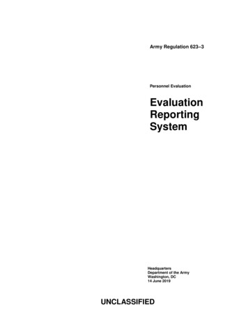
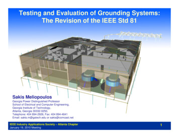
Driving Point Impedance Meters: Hand-Held MetersEasy to Use But Limited ApplicationsAEMC12.4LEM GEO MODEL 15 - Ground Resistance TesterMeasurement Range: 0.025 ohms to 1500 ohms at1.667 kHzAEMCIEEE Industry Applications Society – Atlanta ChapterJanuary 19, 2010 Meeting29
Hand-Held MetersIEEE Industry Applications Society – Atlanta ChapterJanuary 19, 2010 Meeting30
The Smart Ground Multimeter (SGM) Method: Model Based Measurement InstrumentPresently Available Functions1. Ground (System) Impedance Meter2. Touch Voltage Meter3. Step Voltage Meter4. Tower Ground Resistance Meter5. Soil Resistivity Meter6. Ground Mat Impedance7. Transfer Voltage Meter8. Low Impedance/Continuity Meter9. Fall of Potential MethodUser Selected 250V or 500VInternal Switchable Source10. Oscilloscopic Function11. Pole GroundIEEE Industry Applications Society – Atlanta Ch
IEEE Industry Applications Society – Atlanta Chapter. January 19, 2010 Meeting. 1. Sakis Meliopoulos. Georgia Power Distinguished Professor School of Electrical and Computer Engineering, Georgia Institute of Technology, Atlanta, Georgia 30332-0250, Telephone: 404 894-2926, Fax: 404 894-4641 Email: sakis.m@gatech.edu or sakis@comcast.net.