Transcription
Grounding System Theory andPracticeCourse No: E04-027Credit: 4 PDHVelimir Lackovic, Char. Eng.Continuing Education and Development, Inc.22 Stonewall CourtWoodcliff Lake, NJ 07677P: (877) 322-5800info@cedengineering.com
Grounding System Theory and PracticeIntroductionSystem grounding has been used since electrical power systems began. However, manycompanies and industrial plants have used system grounding methods differently. Theproblem of whether a system neutral should be grounded, and how it should be grounded,has many times been misunderstood completely. Therefore, grounding of many systems hasbeen based upon past experience rather than engineering analysis.This course provides applicable information for grounding, such as definitions, reasons forhaving a system ground, the most desirable grounding method, and so on, and how tomeasure ground resistance in order to maintain the grounding system.The definition of grounding is commonly used for both, system grounding and equipmentgrounding. The National Electrical Code (NEC) defines system ground as a connection toground from one of the current-carrying conductors of an electrical power system or of aninterior wiring system, whereas an equipment ground is defined as a connection to groundfrom one or more of the noncurrent-carrying metal parts of a wiring system or equipmentconnected to the system.The following definitions describe power system grounding.-System neutral ground: A connection to ground from the neutral point or points of acircuit, transformer, motor, generator, or system.-Grounded system: A system of conductors in which at least one conductor or point isintentionally grounded.-Ungrounded system: A system of conductors in which there is no intentionalconnection to ground.-Solidly grounded: A system in which there is no intentional impedance in groundconnection; in such a system the line to ground fault currents may equal three-phasefault current.
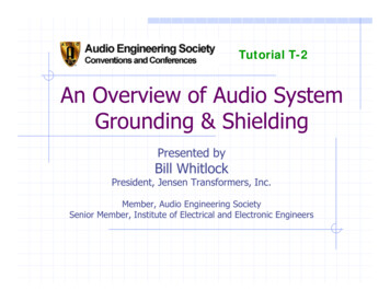
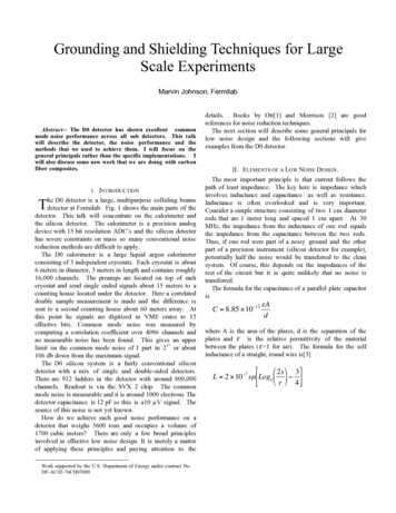
-Resistance grounded: A system grounded through a resistance, the value of which canbe such as to provide either a low- or high-resistance ground system. The lowresistance ground system can have from 25 to several thousand amperes (A)depending upon the value of the resistance. The high-resistance ground systemusually has a value less than 25 A but greater than the value given by XCO/3, whereXCO is the charging capacitance of the system.-Reactance grounded: A system grounded through a reactance.-Resonant grounded: The system grounding reactance value is such that the ratedfrequency fault current flowing through it is substantially equal to the current flowingbetween the conductors and the earth (charging current of the system).-Ground-fault neutralizer: A grounding device that provides an inductive component ofcurrent in a ground fault that is substantially equal to, and therefore neutralizes, therated frequency capacitive component of the ground fault current.Selection of Grounding MethodThe selection of a method for power system grounding is very difficult because a large numberof factors must be considered before a power system grounding method can be chosen. Thefollowing discussion outlines some problems with various grounding methods and explainshow and why grounding systems are applied.Ungrounded SystemsEarly electrical systems were almost universally operated ungrounded. On small systems aninsulation failure on one phase did not cause an outage. The failure could probably be foundand repaired at a convenient time without a forced outage. This worked well as long as thesystems were small. However, as systems increased in size and voltage rating, an increasingnumber of insulation failures produced multiple failures and major faults. At first, the reasonsfor these failures were not understood, and considerable work was done to find why theyoccurred. Figure 1 below shows a typical ungrounded neutral system.
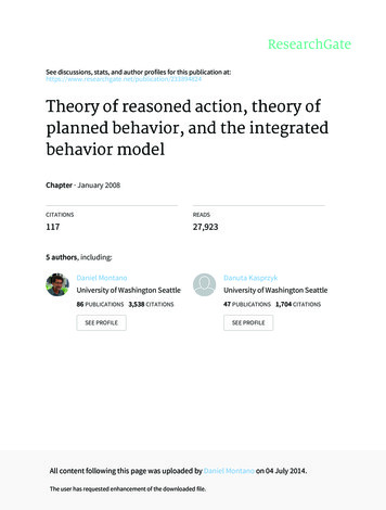
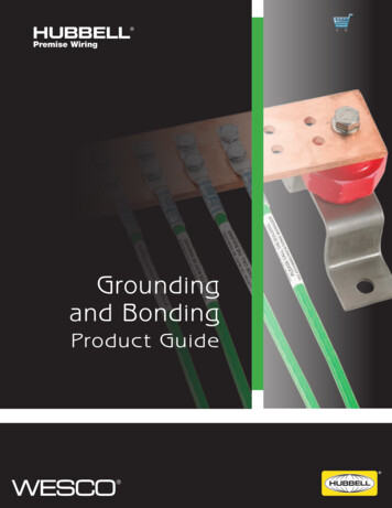
Figure 1. Ungrounded neutral systemActually, it is a capacitive grounded neutral system; the capacitance being the conductorcapacitance to ground. In normal operation, the capacitive current of all three lines is leadingthe respective line to neutral voltages by 90 , and the vector sum of all three currents is zero.Figure 2 shows what happens when the system of Figure 1 is accidentally grounded.Figure 2. Fault on ungrounded neutral systemThe charging current of the faulted phase goes to zero because its voltage to ground is zero.The voltages of the unfaulted phases increase to full line-to-line value with respect to ground,and their charging currents increase proportionally. In addition, because of the 30 shift of theline voltages with respect to ground, the charging currents shift accordingly, and the sum ofthe charging currents in the unfaulted phases is three times the normal value and appears inthe ground, returning to the system through the fault. If the fault can be interrupted, it will mostlikely be done at a current zero. However, since the current leads by 90 in the capacitivecircuit, current zero occurs at the instant of a voltage maximum; thus, if the fault momentarilyclears, a high voltage immediately appears across the fault, and restrike of the fault willprobably occur.In the momentary interval of time that the fault has been cleared, the excessive voltage chargeof the capacitors on the unfaulted lines has been trapped as a direct current (DC) charge.
When the arc restrikes again, the capacitors are again recharged by a line-to-ground voltageadded to the trapped charge. Thus, a restrike after another current zero clearing is moreinevitable, adding another charge.The phenomenon thus probably becomes an oscillating and self-perpetuating build-up involtage, which eventually will lead to an insulation failure on another phase and a major twophase fault. While the first failure may have been a tree branch in the line, the second failuremay occur at some other location entirely, perhaps involving expensive equipment insulation,such as a transformer. Thus, the principal advantage claimed for the ungrounded systemactually caused troubles that resulted in its abandonment.These troubles coupled with other factors led to the adoption of grounded neutral systems insome form. Some of the other factors are as follows:-Because of greater danger to personnel, code authorities frowned on ungroundedsystems.-Equipment costs were generally lower for equipment rated for grounded neutralsystems because of the reduction in insulation permissible. Because graded insulationcould be used, single-bushing, single-phase transformers could be used.-At the higher voltages being used today (69 kV and above), material savings intransformer costs can be realized by employing reduced basic insulation level (BIL).These savings are in addition to the modest savings above, and may amount tosubstantial savings in the cost of transformers in the various voltage classes withreduced insulation. The requirements for safely reducing insulation level demand thatsystem neutrals be grounded. Thus, these savings are not available on theungrounded system.Solidly Grounded SystemsThe simplest and most effective method of grounding is to solidly connect the neutrals of anywye-connected transformers or generators to ground. This method has two major advantages:it is simple and inexpensive in that it requires no extra equipment.
It minimizes the magnitude of the overvoltage that will appear on the unfaulted phases duringa ground fault, resulting in a reduction in the stress on insulation as compared with othermethods.This is the reason that solidly grounded neutrals are a necessity where reduced BIL insulationis to be used. In spite of the advantages of the solidly grounded system, there are associateddisadvantages such that other grounding methods are often used. These disadvantages allstem from the fact that a solidly grounded system produces the greatest magnitude of groundfault current when a fault to ground occurs.It is realized that with a grounded neutral system perhaps 95% or more of all faults start as asingle phase to ground fault. If the amount of ground current that flows can be controlled andthe fault cleared promptly, the amount of damage at the fault will be reduced and the faultprobably restricted so as not to involve more than one phase. This may result in preventingbum downs, reduction in the cost of making repairs, and reduction in the frequency or extentof maintenance on the breakers that interrupt the fault. In the case of machines ortransformers, the difference in repair cost may be that of replacing a few damaged coils ascompared with completely replacing the machine or transformer, which may be necessarywhere oil fires and explosions follow the transformer fault, or where heavy fault currents meltdown coils and burn and weld together expensive areas of laminated electrical steel in thetransformer core or machine stator iron. Since the damage done is approximately proportionalto I2t, it is obvious that much more can be done in the reduction of current than by reductionin time. Under certain conditions, single phase to ground faults can give rise to short-circuitcurrents 50% in excess of three-phase short-circuit current. Thus, breakers whose ratingsmake them entirely capable of interrupting are typically used.Three-phase faults may be in severe difficulty handling a single phase to ground fault. In viewof this, the potential savings in damage and repair costs or avoiding the cost of having to installlarger breakers may justify avoiding the simple and inexpensive solidly grounded system infavor of a more complex and expensive system that will provide control of the amount of faultcurrent.Reactance and Resistance Grounded SystemsReactors are commonly employed as neutral impedance for ground current limitation whenthe amount of current reduction is small. This is because reactors of low ohmic value used tohandle large quantities of current can be built quite inexpensively as compared with a resistor
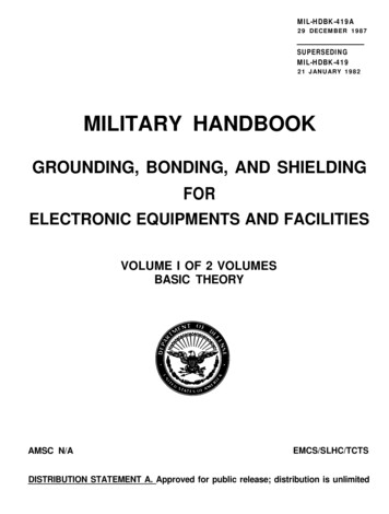
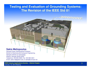
for the same current limitation. Reactors used to provide current limitation to values less thanapproximately 30% to 50% of the value are not practical. This is true partly because the highohmic values necessary to provide the higher current limitation makes them more expensivethan resistors, and partly because high values of reactance grounding approach the conditionsof ungrounded systems and give rise to high transient voltages.Resistors are generally used where it is desired to limit fault currents to moderate to smallvalues. The directly connected resistor is not practical for extremes of current limitation.Reactors are used where a small reduction of current is required, because a resistor largeenough to handle the large quantities of current remaining would have to have resistor gridsof tremendous cross section or many parallel grid paths, and as a result would be veryexpensive. On the other hand, if extreme limitation of ground current by resistors is desired,the resistor again becomes excessively expensive. This is because there are maximum valuesof resistance that it is practical to build into a resistor unit before the cross-sectional area ofthe resistance conductor becomes so small as to make it too susceptible to mechanical failurefrom shock, rust, corrosion, and the like. Thus, to get very high values of resistance, theresistor must be made up by connecting a tremendous number of moderate resistance unitsin series, which makes it expensive and bulky.A variation of the directly connected resistor is used, where it is desirable and practical to limitground fault currents to extremely low values to avoid the expense and difficulties of the veryhigh value resistance. A distribution transformer is connected between the neutral to begrounded and ground. A resistor is then connected across the secondary of the transformer,as shown in Figure 3.Figure 3. Impedances in the resistor grounded system
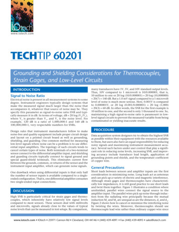
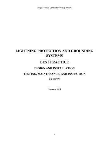
The actual 0.25 Ω resistor in the transformer secondary is stepped up in value as it appearsto the generator neutral by the square of the transformer ratio of 13,200/240 or 3024 times.Thus, the 1/4 Ω secondary resistor appears as a 756 Ω resistor in the generator neutral. Thislimits the ground fault current to a maximum of 11.5 A. This represents only a small percentof current on the basis of machine full-load current and of the maximum three-phase faultcurrent available. This is representative of the extreme of current limitation. It accomplishesthe ultimate in the reduction of fault damage. Further reduction of fault current would bedangerous, because if it were attempted, the capacitance of the generator and step-uptransformer windings and the generator lead bus duct would predominate over the highervalues of resistance, and the system would approach the characteristics of the originalungrounded system of Figure 1 with its dangers of arcing grounds.Resonant GroundingOne of the earliest methods of attempting to eliminate the faults of the ungrounded systemand still retain the claimed advantages for it was by means of resonant grounding using thePeterson coil. This method attempted to eliminate the fault current that could cause the arcingground condition. Figure 4 shows the system of Figures 1 and .2 with the Peterson coil applied.Figure 4. Resonant grounding systemThis is simply a tunable, iron-cored reactor connected between neutral and ground. It is tunedso that the current it furnishes matches the current furnished by line capacitance under faultconditions. Under normal system conditions, it does not carry current. However, upon theoccurrence of a fault it contributes a reactive component of current through the fault matchingthe capacitive component. Since the two currents are 180 out of phase, they cancel. Thisleaves no current at the fault, minimizes the chance of restrike, and thus eliminates the cause
of voltage build-up. The ground-fault neutralizer is said to be effective in 70% to 80% of thefaults. It is not in great favor because it is not 111% effective, because of its expense and theexpense of the equipment necessary to protect it in the 20% to 30% of the cases when it doesnot work. The principal cause of its failure to work is improper tuning. This might seem to beeasily corrected. However when it is realized that retuning would be required upon each feederextension or rearrangement for each emergency switching condition, or that even if keptproperly tuned the system could be detuned by a broken conductor associated with the faultit was to clear, some of the difficulties of its application can be realized.It can work well in a three-phase radial circuit. However, it is not practical in a tie feeder ornetwork system unless it is blocked off by delta transformers or other zero-sequenceimpedance isolators so that the tuned setting required can be definitely known and is notvariable because of system operating conditions.Grounding Ungrounded SystemsSo far the discussion of grounding has assumed a wye-connected neutral to ground. This isnot always the case, and in some cases it is not a three-phase system that it is desired to begrounded. For situations of this kind a grounding transformer is used. This may be aconventional wye-delta transformer of suitable rating, or a special zigzag wye unit may beused. Once the neutral is established, any of the grounding methods already discussed maybe employed, provided the rating of the grounding transformer is adequate for the amount ofcurrent permitted by the grounding method used. Figure 5 shows the setup of a zigzag wyetransformer used for the grounding. In the selection of grounding equipment and methods,many factors must be considered. It is desirable from the reduction of fault damage, repaircosts, and switching equipment maintenance to limit ground fault current as much as possible.However, the greater the limitation of current, the higher the possible transient overvoltagesthat will be encountered. This will determine the equipment insulation levels required and therating of lightning arresters required to protect the equipment, and will consequently affectcosts. Therefore, these factors are in conflict with the desire for maximum fault limitation.Whether resistors or reactors are used will determine the degree of overvoltage expected ona given system for a given degree of current limitation, and thus affects the selection of theuse of resistors or reactors.
Figure 5. Setup of a zigzag wye transformerWhenever grounding of any kind is used, it is obvious that fault current will flow when anormally ungrounded conductor becomes grounded. It is necessary that relays, fuses, or otherprotective devices sense and operate to clear the fault. Since the degree of current limitationemployed may well have a serious effect on the ability of these devices to operate as desired,it follows that the degree of current limitation that can be employed may well be determinedby the sensitivity of protective devices used, or, conversely, the type and sensitivity of the
protective devices required may be determined by the degree of current limitation selected.However, since a multiplicity of feeders at generator voltage depends upon ground overcurrentrelays for their ground fault protection, ground fault current must be kept up to a value that willgive adequate relay operating torque for any and all ground faults on them, with reasonablecurrent transformer ratios and relay current ranges. Thus, the selection of the value to whichthe ground fault is to be limited becomes the problem of making a selection between theminimum ground fault current to limit damage, the minimum ground fault that will giveadequate protective device operation, and the maximum ground fault current that thegenerator windings can tolerate before there is danger of the magnetic forces forcing windingsout of the generator armature slots. The extreme ground current limitation can be used onlywhere there are no feeders at generator voltage that must have ground fault protection, andwhen delta-wye transformers isolate the zero-sequence network for which ground faultprotection at this very low current level must be provided to a very small number of equipmentunits. Even then, very special relaying methods must be employed. In conclusion, severalimportant points with respect to impedance grounding of system neutrals are so obvious thatthey are often overlooked.1. Since grounding equipment is electrically active in a circuit only during a ground fault,considerable money can be saved by buying equipment rated for short time duty.Grounding equipment for a station with all underground circuits will be expected to besubjected to very infrequent faults, and since cable faults are usually permanent,repeated reclosing attempts will probably not be made. Under these circumstances ashort time rating of the grounding equipment of 11 sec or less may be adequate.However, grounding equipment installed in a station having all overhead circuits willbe subjected to the cumulative heating effect of perhaps many closely spaced feederfaults during severe storm conditions, with each circuit outage being accompanied byseveral unsuccessful closing attempts. Under these conditions, equipment having arating on a 10 min or more basis may be inadequate.2. Impedance neutral grounding equipment must always be considered hot because if aground fault occurs in the system, it will raise the neutral to full phase to ground voltage.This not only poses a safety problem but also creates the problem of how to maintainthe equipment, unless the machine, bus or station, for which the impedance furnishesthe ground, is shut down.
3. Where a multiplicity of grounding units is employed, care must be exercised inswitching facilities for their transfer to avoid the danger that someone will get caughtoperating disconnects for the transfer just as a ground fault occurs. If multiple units areused, care must be exercised to assure that the protective relaying will operate andcoordinate properly through the range of conditions possible with the multiple units.4. Where impedance grounding is used, no other neutrals in the same zero-sequencesystem may be grounded except through the same impedance. To do so will shunt orshort circuit the original impedance and raise the ground fault current above thedesired design value.Selection of Grounding SystemAs discussed earlier, the various methods of grounding commonly used are solidly grounded,resistance grounded, reactance grounded, and ground fault neutralizer grounded. Theungrounded system, in the true sense of the word, is grounded, because the chargingcapacitance from the phase conductor to earth acts as the grounding point. The variousgrounding methods are shown in Figure 6. The selection of a grounding system should bebased upon the following systems factors:-Magnitude of the fault current-Transient overvoltage-Lightning protection-Application of protective devices for selective ground fault protection-Types of load served, such as motors, generators, etc.
Figure 6. Various grounding methods – equivalent schemesSolidly Grounded SystemA solidly grounded system is one in which a generator, transformer or grounding transformerneutral is directly grounded to earth or station ground.Because the reactance of source (generator or transformer) impedance is in series with theneutral circuit, this system cannot be considered a zero impedance circuit. In nearly allgrounded systems, it is desirable to have the line to ground fault current in the range of 25%to 110% of three-phase fault current in order to prevent the development of high transientovervoltage. The higher the ground fault current, the less are the transient overvoltages.Ground-neutral-type lightning arresters may be applied on this system provided that theground fault current is at least 60% of three-phase fault current. Another way of expressingthis value is to express the reactance and resistance ratios as follows:-X0 is the zero-sequence reactance-X1 is the positive-sequence reactance-R0 is the zero-sequence resistance
Normally, direct grounding of the generator is not desirable because the ground fault currentmay exceed three-phase fault current. Since the generator is rated for maximum three-phasefault current, it is not desirable to have higher ground fault currents than three-phase faultcurrent. Therefore, most grounded systems having generators are grounded through lowreactance values to keep ground fault currents less than three-phase fault current. Generally,low-voltage systems (i.e., below 600 V) are solidly grounded. Medium-voltage systems maybe either solidly or low resistance grounded.Low-Resistance GroundingIn low-resistance grounding, the neutral is grounded through a resistance of low ohmic value.The reasons for using the resistance grounding system are as follows:-To reduce the ground fault current to prevent damage to switchgear, motors, cablesand the like-To minimize magnetic and mechanical stresses-To minimize stray ground fault currents for personnel safety-To reduce the momentary line-voltage dips by clearing of ground faultsThe line-to-ground voltage that may exist during fault conditions can be as high as the voltagepresent on ungrounded systems. However, the transient overvoltages are not so high. If thesystem is properly grounded by resistance, there is no danger from destructive overtransientvoltages.High-Resistance GroundingIn this system, the neutral is grounded through a resistance of high ohmic value. The line-toground voltage of unfaulted phases during a ground fault is nearly equal to line-to-line voltage.If the insulation system was selected for a grounded system, it will be subjected to anovervoltage condition during a line-to-ground fault. The ground fault current available in thistype of system is very small, usually 25 A or less. It should be remembered that when usingthis system the ground fault current should never be less than the charging current. Moreover,the lightning arresters for this system should be the ungrounded type. This type of system issubject to the following types of overvoltage conditions:-Ferroresonance type, that is, resonance effects of series inductive–capacitive circuits-Limited transient overvoltage conditions-Overvoltage conditions due to direct connection to higher voltages
The reasons for using high-resistance grounding are similar to those for low-resistancegrounding except that in this system ground fault current is limited to a very small value.Reactance GroundingIn a reactance grounded system, the neutral circuit is grounded through a reactor. In general,reactance grounding is used for grounding generator neutrals. The value of the reactor chosenis usually such that the ground fault current is not less than 25% of three-phase fault currentto prevent serious transient overvoltages during ground fault clearance. The value of X0 mustbe less than or equal to 10 times the X1 value for this type of system.Ground-Fault Neutralizers (Resonant Grounded)In this system, a reactor having a specially selected high value of reactance is connected inneutral connection to ground. The current that flows through the reactor, during a line-toground fault condition, is equal to, and 180 out of phase with, the charging current that flowsin two unfaulted phases. Under this condition, the two currents cancel, leaving the faultedcurrent due only to resistance. Because resistive current is in phase with the voltage, the faultcurrent is quenched when both the voltage and fault current pass through zero axis.A precaution required in this system is that care must be taken to keep the ground-faultneutralizer tuned to the system capacitance. If any switching is done to take circuits out, theneutralizer reactance values must be changed by adjusting neutralizer taps. Ground-faultneutralizers have been used only to a limited extent and are not as common as the othersystems of grounding.Soil Resistance MeasurementThe resistance to the earth of any earth electrode is influenced by the resistivity of thesurrounding soil. This will depend to a large extent on the nature of the soil and its moisturecontent. Resistivity may change with depth, temperature and moisture content, and can varyfrom place to place depending on the strata of the soil and rock formation. The soil resistivityfigure will have a direct impact on the overall substation resistance and how much electrodeis required to achieve the desired values. It will also influence separation distances betweentwo adjacent earth systems (e.g. HV and LV earths at hot distribution sites). The lower theresistivity, the fewer electrodes is required to achieve the desired earth resistance value. It isan advantage to know the resistivity value at the planning stage as this gives a good indicationof how much electrode is likely to be required. This section describes the different methods
that can be used to determine the soil resistivity.The resistivity of any material is defined as the electrical resistance measured between theopposite faces of a uniform 1m3 cube. The accepted symbol is ‘ρ’ and is measured in ohmmeters (Ωm). Typically soils can vary from a few ohm-meters for very wet loams up tothousands of ohm-meters for granite. In practice soil is very rarely homogenous and so thevalues indicted should be taken as a rough guide only. The Wenner (four terminal) test is themethod for determining soil resistivity. The soil resistivity data can influence the chosen sitelocation as well as the decision on the best type of earthing electrode system to be installed.For example, it helps to decide if it’s an advantage to drive rods to a greater depth or whetherto increase the surface area by installing more buried tape. The survey can produceconsiderable savings in electrode and installation costs when trying to achieve the requiredresistance.If the results gained from the soil resistivity survey are unclear then soil modelling can beundertaken. With up-to-date techniques a fairly good and accurate soil model can beproduced. Also core drilling usually associated with a geo-technical survey will give anaccurate soil model and can be used to check measured soil resistivity results. Soil resistivityis also important in determining the separation distances between the HV and LV electrodesat hot distribution substations. A Wenner test could be used but a simpler procedure has beendeveloped for use at these sites. This is known as the ‘one’ or ‘driven rod method’ and givesan average value of soil resistivity.Once an electrode system is installed then the actual resistance value must be measured andrecorded. If this falls short of the design value then additional electrodes will be required torectify the problem.Wenner Method for Measuring Soil Resistivity at Primary/Grid sitesA four-terminal earth tester is required, equipped with four probes and connecting leads. Thelatter shall be mounted on reels for easy run-out and recovery and should be checked forcontinuity and condition prior to use. The calibration of the instrument should be checkedbefore taking any readings, using the test resistors supplied with the instrument. Provisionshould also be made for a laboratory re-calibration check of the instrument every year.
Checks for other buried equipmentBefore carrying out any testing, checks shall be made from other utility records, your owncable records and using radio detection equipment, for the presence of any buried cables,earth conductors or other metalwork. These could adversely affect the accuracy of thereadings taken, particularly if they are parallel to the measurement route. Conventional metaldetectors will only locate very large pipelines or objects close to the surface, so they cannotbe relied upon. Location equipment should be used in the inductive mode (to locate pipeswhich are not connected to the earthing system), and d
The actual 0.25 Ω resistor in the transformer secondary is stepped up in value as it appears to the generator neutral by the square of the transformer ratio of 13,200/240 or 3024 times. Thus, the 1/4 Ω secondary resistor appears as a 756 Ω resistor in the generator neutral. This limits the grou