Transcription
Application NoteInsulation Resistance Testing– Megger TestingPurpose:Insulation resistance testing is a non-destructive test procedure. The test measures the insulation resistance between the phases and/or between phase and ground. It is commonly usedin the industry for acceptance testing prior to energizing the cable and for maintenance testingprograms.General Testing Information For single conductor non-shielded cable on a reel, insulation resistance testing cannot beperformed due to the fact that low voltage single conductors do not have a grounding conductor, shield or ground plane. For other cable on a reel, insulation resistance testing can be performed provided the sealing caps are removed. The procedure to test these cables is outlined below. NOTE: It is important to remove sealing caps from both ends of the cable to be tested. Residue inside the sealing cap can be conductive and lead to false readings.Equipment: DC Insulation Tester (Megger)Safety: Before conducting tests on cables, verify circuits are de-energized. Follow all safety practices according to NFPA 70E and NESC C2-2012. Follow insulation tester instructions and guidelines. Only qualified persons should perform this testing.Preparation: Ensure that test equipment is in good working order and has been calibrated within the lastyear. Clean up the area. Good housekeeping and environmental conditions are important sinceinsulation resistance readings are affected by dirt, moisture and heat. Disconnect cables from equipment on both ends. Clean cable ends/lugs with appropriate cleaning solution. If lugs or accessories are not being used, cutback the cable as described below.01/23/20172202www.southwire.com
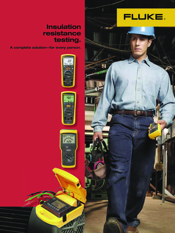
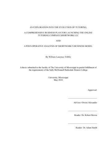
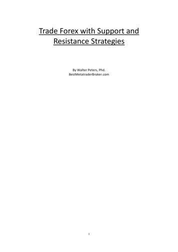
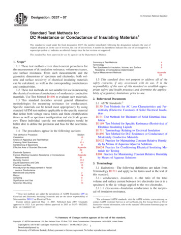
Insulation Resistance Testing On the end not being connected to the test equipment, make sure sufficient clearance (six inches or more)is maintained between cable ends and the ground plane.For 600–5,000 Volt Non-Shielded Cable Measure 0.5” from cable end. Make a 360 ring cut on insulation without cutting intothe conductor. Make a longitude cut on insulation from the ring cut tocable end. Remove the cables insulation from the end of the cable. Clean the cable end to remove dirt and contaminates that may be present.0.5”For 2,400 - 35,000 Volt Shielded Cable Mark the cable jacket 8" from cable end. At this location, make a 360 ring cut on cable jacket. Next make a longitude cut on thejacket from ring cut to cable end. Removethis section of the jacket, taking care not tonick tape shield below.1”1”8”6”0.5” Measure 1” from the cable jacket towardcable end and apply a constant force spring at that mark, remove the tape shield by using the spring as aguide. Tear the tape off against the constant force spring. Measure 2” from cable jacket to the semicon and apply a constant force spring at that mark. Make a 360 ring cutat this location. Now make two to three longitude cuts from the ring cut to cable end, taking care not nick insulationbelow. Remove the semi-con.Measure and mark the insulation 0.5” from cable end. Apply a constant force spring at the mark. Make a 360 ring cut at the mark, then make a longitude cut from the ring cut to cable end. Be careful not nick conductor below.Remove the insulation.Test Procedure: At the test end, ground the conductors in the circuit except for the conductor being tested. This will ensure that the tester is only measuring leakage current in the selected conductor. Connect the appropriate tester leads to the conductor to be tested and to the adjacent conductor, shield,or ground plane (or metallic conduit). Use the guard circuit if available on the insulation resistance test set. The guard circuit will remove anysurface leakage on the conductors and improve the accuracy of the test readings. The guard circuit shouldbe connected as shown in the illustration above. See your testers instruction manual for details. Make sure both cable ends under test are suspended in free air. Having the cable end near conductiveSouthwire Company, LLC One Southwire Drive, Carrollton, GA 30119 www.southwire.compage 2
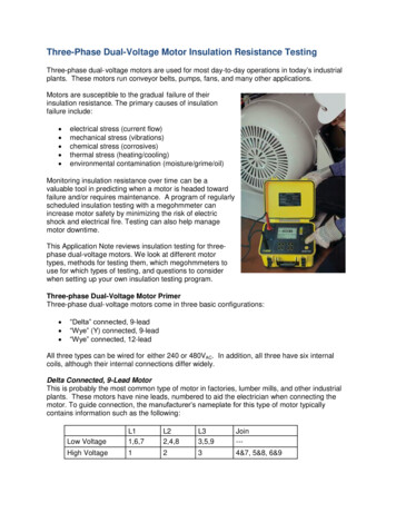
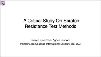
Insulation Resistance TestingShielded CableNon-Shielded537 M ΩTEST G-path can affect the test and reduce the insulation resistance reading.Suspend and isolate the test set leads in air as much as possible. Do not allow the leads to touch duringthe test.Do not touch or move conductor during testing as results will be affected.Perform the test and record the resistance readings on the attached form. Be sure to record results for atleast 10 minutes.Depending on the type of cable, a different number of tests will be required to test all the conductors. UseTable 1 to determine which conductors need to be tested and what the ground reference should be.After a conductor is tested, ground the conductor for a period of at least 4 times the duration of the test(For a 10 minute test the conductor should be grounded for 40 minutes). This will safely remove anycapacitive charge left on the conductor.Table 1Southwire Company, LLC One Southwire Drive, Carrollton, GA 30119 www.southwire.compage 3
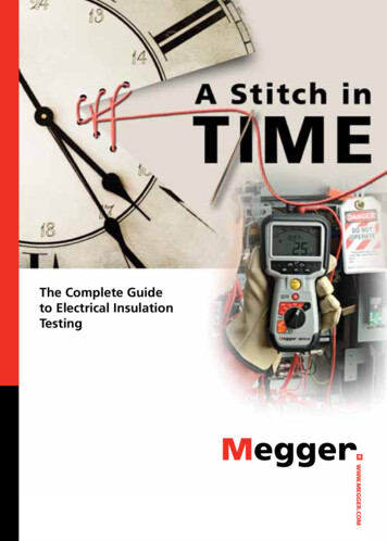
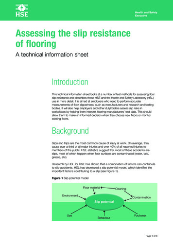
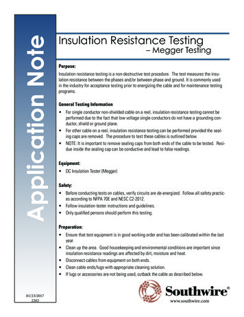
Insulation Resistance TestingCable TypeMedium Voltage ShieldedMedium Voltage Non-ShieldedLow Voltage Multi-ConductorTest to Performϕ to Shieldϕ to ϕϕ to Groundϕ to ϕϕ to Groundϕ to NeutralNotesConductor shieldEarth ground or the cable’s metallic conduitEarth ground or the cable’s metallic conduitNeutral to GroundExampleYou have a single conductor 500 kcmil, 15kV cable. You perform this insulation resistance test on the cableand record the data on a copy of the attached form:For a good cable, you will see results similar to those on the following page. The resistance values willincrease over time due to capacitive and insulation charging. As the charging becomes more complete the resistance readings will level out. How long that will take will depend upon the cable size, capacitance, length,and other factors. A 10 minute test should be long enough to get good test results on most cables.The highest resistance reading should be at the 10 minute mark. You will need to normalize that value for astandard cable length. To do this you will need to use the equation at the bottom of the form. In this case wehave:R equal to 16.8 GΩL equal to 4020 ft.This gives us:RΩ 1000ft R x L/1000 16.8 x 4020/1000 67.5 GΩ 1000ft. 67,500 MΩ 1000ft.Comparing this result with the correct row of Table 2 shows that our cable passes the insulation resistancetest.If the Cable Does Not PassIf a cable does not pass the test the cable still may be good but additional cable evaluation should be performed. The first thing to check is the cable testing environment and cable preparation. Dirty cables and highhumidity can have a significant negative impact on the test results. Are both cable ends prepped correctlyand isolated from any possible conductive path? Is the cable damp? Try cleaning the cable ends with cablecleaning wipes and test again. Is the cable isolated from other components? The problem may not be withthe cable but could be with the cable connectors, terminations or transformers or other equipment the cable isconnected to. While disconnecting the cable from the circuit can be a tedious task, it can make a big difference in the test results.If after trying all the above still does not yield valid test results contact your Southwire representative foradditional information.Southwire Company, LLC One Southwire Drive, Carrollton, GA 30119 www.southwire.compage 4
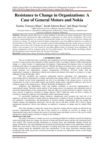
Insulation Resistance TestingDate:Temperature:Humidity:Cable Length (L):Tester Name:12/19/1670 F52%4,020 ft.S.W.Circuit:Cable SizeRated Voltage:Test Voltage:Manufacturer:Reel #1500 kcmil15kV2500VSouthwireelxResistance (R) in: MΩ GΩPhase A – GNDCapacitance30 sec1 min2 min3 min4 min5 min6 min7 min8 min9 min10 minRΩ .8Phase B – GNDPhase C – GNDpmaxE67.5Insulation Resistance, RΩ 1000ft R x L/1000ϕwhere:R Insulation Resistance Measurement of CableL Cable LengthSouthwire Company, LLC One Southwire Drive, Carrollton, GA 30119 www.southwire.compage 5
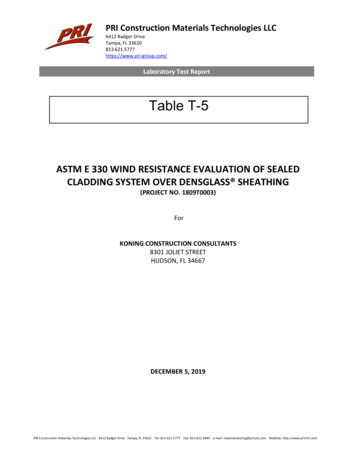
Insulation Resistance TestingTable 2Cable Voltage RatingMinimum Test VoltageMinimum Insulation ResistanceVoltsVolts, DCMΩ 1000 20,000Reference NFPA 70E: National Fire Protection Agency, Standard for Electrical Safety in the Workplace. NESC: National Electrical Safety Code C2-2012 published by the IEEE.Disclaimer: The information contained herein is being furnished for informational purposes only and SouthwireCompany, LLC makes no warranty relative to such information.Southwire Company, LLC One Southwire Drive, Carrollton, GA 30119 www.southwire.comCopyright 2017 Southwire Company, LLC. All Rights Reserved Registered trademark of Southwire Company, LLCpage 6
Insulation Resistance TestingDate:Temperature:Humidity:Cable Length (L):Tester Name:ft.Circuit:Cable SizeRated Voltage:Test Voltage:Manufacturer:Resistance (R) in: MΩ GΩPhase A – GNDPhase B – GNDPhase C – GNDCapacitance30 sec1 min2 min3 min4 min5 min6 min7 min8 min9 min10 minRΩ 1000ftInsulation Resistance, RΩ 1000ft R x L/1000ϕwhere:R Insulation Resistance Measurement of CableL Cable LengthSouthwire Company, LLC One Southwire Drive, Carrollton, GA 30119 www.southwire.compage 7
Insulation Resistance TestingDate:Temperature:Humidity:Cable Length (L):Tester Name:ft.Circuit:Cable SizeRated Voltage:Test Voltage:Manufacturer:Resistance (R) in: MΩ GΩPhase A – Phase BPhase B – Phase CPhase C – Phase ACapacitance30 sec1 min2 min3 min4 min5 min6 min7 min8 min9 min10 minRΩ 1000ftInsulation Resistance, RΩ 1000ft R x L/1000ϕwhere:R Insulation Resistance Measurement of CableL Cable LengthSouthwire Company, LLC One Southwire Drive, Carrollton, GA 30119 www.southwire.compage 8
Insulation Resistance TestingDate:Temperature:Humidity:Cable Length (L):Tester Name:ft.Circuit:Cable SizeRated Voltage:Test Voltage:Manufacturer:Resistance (R) in: MΩ GΩPhase A – NeutralPhase B – NeutralPhase C – NeutralNeutral – GNDCapacitance30 sec1 min2 min3 min4 min5 min6 min7 min8 min9 min10 minRΩ 1000ftInsulation Resistance, RΩ 1000ft R x L/1000ϕwhere:R Insulation Resistance Measurement of CableL Cable LengthSouthwire Company, LLC One Southwire Drive, Carrollton, GA 30119 www.southwire.compage 9
Insulation resistance testing is a non-destructive test procedure. The test measures the insu-lation resistance between the phases and/or between phase and ground. It is commonly used in the industry for acceptance testing prior to energizing the cable and for maintenance testing programs. General Testing Information For single conductor non-shielded cable on a reel, insulation resistance .