Transcription
Ground Fault Protection for an Ungrounded SystemEE5223 Electrical Power System ProtectionAdam Heskitt and Hillori MitchellFinal Draft 4/26/2013
Executive SummaryThe purpose of this report is to demonstrate the knowledge of key concepts presented in EE5223Electrical Power System Protection. This project includes the development of a ground fault protectionscheme for an ungrounded system, starting from the basic concepts presented in the course textbook andextending into a detailed implementation and simulation results.The ground fault protection scheme developed involves an overvoltage relay, connected acrossbroken delta-connected VTs, that monitors zero sequence voltage. Sequence networks and calculationsare used to explain the setting of the overvoltage threshold for a single line-to-ground fault. Other faulttypes are also discussed in terms of what the overvoltage relay will be observing in each case.Implementation details will include ballast resistance selection and relay settings. Also, the commonpractice of connecting indicating lamps phase-to-phase to determine the faulted phase(s) is modified toprovide remote indication. The results of an ASPEN simulation for a given ungrounded system arediscussed and compared to hand calculations generated for various fault types. Finally, a conclusion ofthe system performance is included with directions for future work.2
Table of ContentsExecutive Summary . 2Statement of Contributions . 4Introduction . 5Background . 5System Grounding Principles. 5Ungrounded System Ground Fault Detection . 5Existing Voids and Resulting Opportunities . 7Proposed Approach and Application . 8Overview . 8Example System Development . 9Implementation . 10Conclusion . 13Recommendations for Continued Work . 14Appendix I: Journal ReviewAppendix II: Fault Voltage Hand CalculationsAppendix III: ASPEN Voltage DiagramsAppendix IV: Equipment Sheets3
Hillori Mitchell4/26/13
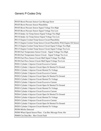
IntroductionThe purpose of this term project is to develop a ground fault protection scheme for an ungroundedpower system that will ensure adequate protection for a line-to-ground fault and to study how thisprotection scheme reacts to other fault types (double line-to-ground, line-to-line and three phase). Theparameters of this system are based on a client’s relaying design report. The protection scheme includes avoltage transformer (VT) connected in wye-grounded to broken-delta configuration and a Basler 59Novervoltage relay. Relay settings and configuration for the overvoltage relay will be determined, as wellas the sizing requirements of a ballast resistance. Further, a remote indication scheme will be developedthat replaces traditional indicating lamps. Hand calculations will be completed for all fault types in thegiven system and used to verify the ASPEN OneLiner model of the system.BackgroundSystem Grounding PrinciplesProper system grounding is essential in protecting against transient overvoltages that result insignificant damage to equipment and/or people working at the substation. Currently, there are varioussystem grounding principles that can be applied and are differentiated by the impedance or lack thereofbetween the neutral point of the three-phase system and ground. In a high-impedance grounded system ahigh resistance or inductance is inserted into the ground connection. This limits fault current levels oreven negates system capacitance to largely eliminate fault current, respectively. Low-impedance andsolidly grounded systems have relatively higher fault currents, but facilitate easier detection of groundfaults due to voltage drop along the line. This project focuses on a system that has no intentional groundconnection, known as an ungrounded system. Although there is no intentional ground connection theneutral is still coupled to ground via system capacitance [3].For a ground fault on an ungrounded system, the fault currents remain close to zero as the faultedphase voltage approaches the same potential as ground. The unfaulted phase voltages increase withrespect to ground and resulting in an overvoltage condition. These properties lead to a unique method fordetecting and protecting against ground faults for an ungrounded system.Ungrounded System Ground Fault DetectionAn example of an ungrounded system is shown in Figure 1 below. The secondary windings of thetransformer are connected in delta configuration and the system feeds an ungrounded load. For a single5
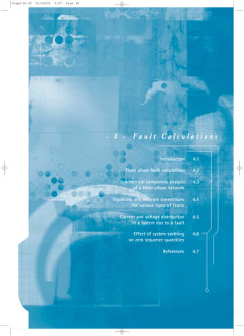
line-to-ground fault, the sequence diagrams would be connected in series as shown. Since the deltaconnected transformer represents an open circuit in the zero-sequence diagram, the only path for the faultcurrent to flow through is the system capacitance. This impedance is very high relative to the seriessystem impedances, so the fault current and negative sequence voltage approaches zero while the positivesequence (source voltage) and zero sequence voltages are equivalent [1].SLGFaultUngroundedLoadsN1POSSEQVsX1c 0ZEROSEQX0cV0I0Z1sZ1lineFigure 1: Ungrounded System and Sequence DiagramSince the fault current is low, a typical ground overcurrent relay is inefficient for detecting groundfaults in an ungrounded system. Instead, detection of overvoltage conditions must be relied on to indicatea ground fault. The sequence and phase voltages for a single line-to-ground fault in the same ungroundedsystem are shown in Figure 2 below. It can be observed that the faulted phase voltage collapses to zero atthe fault while the unfaulted phase voltages increase to 3 times their original magnitude, equal inmagnitude to the line-to-line voltages. Further, the angle between the two unfaulted phase voltagesdecreases to 60 . It is interesting to note that the phase-to-phase voltages remain unchanged, whichfacilitates the continued operation of ungrounded loads. However, the increased phase-to-ground voltageson the unfaulted phases predicate increased insulation levels versus a grounded system. Lastly, the phasor6
diagrams show that the neutral-to-ground voltage magnitude during a fault approaches that of the phasevoltage under typical, unfaulted conditions. This development is the foundation for the following faultdetection philosophy and is discussed in [1] and [3].VA1POSSEQ1VC1VA2 VB2 VC2 0During FaultPre-FaultVBAA, GN, GNEGSEQPHASEVOLTAGESGround PlaneCBNVA0 VB0 VC0ZEROSEQCBFigure 2: Sequence and Phase VoltagesThe obvious approach to detect ground faults in such a system would then be to look for these voltagecharacteristics. Specifically, by connecting the phase voltages in series in a broken delta connection, thevoltage at the break in the delta can be monitored. During a fault, this voltage will increase to three timesthe regular phase-to-neutral voltage, as shown in Equation 1 below. Accordingly, an overvoltage relaycan be connected across the broken delta-connected auxiliary VTs to detect a ground fault.𝑽𝑨𝑮 𝑽𝑨𝑵 𝑽𝑵𝑮 𝟎𝑽𝑩𝑮 𝑽𝑩𝑵 𝑽𝑵𝑮 𝟑𝐕𝐋𝐍 𝟏𝟓𝟎 𝑽𝑪𝑮 𝑽𝑪𝑵 𝑽𝑵𝑮 𝟑𝐕𝐋𝐍 𝟏𝟓𝟎 𝑽𝒓𝒆𝒍𝒂𝒚 𝑽𝑨𝑮 𝑽𝑩𝑮 𝑽𝑪𝑮 𝟑𝐕𝟎 𝟑𝐕𝐋𝐍 𝟏𝟖𝟎 Equation 1: Broken Delta VoltageExisting Voids and Resulting OpportunitiesThe issues associated with overvoltage ground fault detection for ungrounded system are wellstudied, with foundational papers dating back to at least 1951 [8]. In the specific case of using a singleinput overvoltage relay connected across broken delta-connected VTs, most existing voids in capabilityare inherent to the configuration and system grounding type. For example, detecting where the fault7
occurs on the faulted line (line end or close in) is difficult due to the low fault current which leads to aconstant fault voltage along the line [3]. Similarly, faults other than single line-to-ground are not easilydetected by this overvoltage relay. Some authors look past the single line-to-ground fault case and insteaddevelop overcurrent detection and protection methods for a second simultaneous fault, which is typicallythe more severe fault case in an ungrounded system [6]. Further work is ongoing to study the effects offerroresonance in VT circuits, which involves sizing the ballast resistance connected in parallel with theovervoltage relay to limit resonance between VT inductance and system capacitance [11], [13], [14].However, practical rules-of-thumb have long been developed on this subject based on engineeringexperience [12].Another existing void is detecting which phase is faulted to ground. A common method used is toconnect indicating lamps line-to-line across the broken delta-connected VTs. In this scheme, a darkenedlamp would indicate a fault on that phase. This method is limited to local observation, which is onlyuseful if the system is designed to continue to operate for some time in the case of a single line-to-groundfault. Most modern systems would also have a numerical relay monitoring each phase, which couldprovide the remote communication needed. However, some utilities and engineers still prefer to use thesingle relay method [15]. Another fault location method involves connecting a signal generator to the zerosequence winding of the transformer [2]. When a fault occurs the relay initiates the signal generator tosend a current through the circuit that will then return through the ground network of the fault. This signalallows the relay to determine the electrical distance that the fault occurs away from the relay, thuslocating where the fault occurred in the system. A review of the journal article explaining this techniquecan be found in Appendix I.The opportunity to develop a method of identifying the faulted phase in an ungrounded system andcommunicating information to a remote system, without resorting to three-phase voltage sensing by anumerical relay or signal injection, was embraced by the authors. In addition, the voltage sensed by therelay during other types of faults (double line-to-ground, line-to-line, three-phase) will be investigated inorder to better understand the system and overvoltage relay reactions.Proposed Approach and ApplicationOverviewThis report involves the development and implementation of remote indicators in a broken deltaground fault protection scheme for an ungrounded power system. Also, the voltage sensed by an8
overvoltage relay connected to the broken delta will be explored for each fault scenario and normaloperation.An example ungrounded system will be defined along with its parameters for ASPEN simulation.Next, VT and relay connections will be illustrated, using the Basler 59N as an example. Relay settingsand ballast resistance will be recommended based on the system parameters. The implementation detailsof the remote indicators will be explained, and the testing methodology to explore relay performanceduring all fault cases and normal operation will be explored. Finally, the results of these tests will bepresented.Example System DevelopmentThe first step of implementation for this project is to define a system configuration for study. Thissystem is based on a typical utility’s distribution substation, with a two-winding, 120-4.8 kV delta-deltaconnected transformer. The system one-line diagram is shown in Figure 3 and the system parameters foruse in ASPEN are given in Table 1.SLGFault120 kVUngroundedLoads4.8 kVFigure 3: Ungrounded System One-Line DiagramTable 1: System ParametersSource (Generator)TransformerSubtransient 0.27351 j2.51826 ΩR 0ΩTransient 0.27351 j2.51826 ΩX .08 ΩSynchronous 0.27351 j2.51826 ΩR0 0 ΩNeg. Sequence 0.27357 j2.51776 ΩZero Sequence 2.8823 j5.62207 ΩX0 .08 ΩMVA (per ø) 24 MVANeutral Imped. 0 ΩShort Ckt. MVA 3858.4 MVALineR 0ΩLoad (Ungrounded)Constant Power 10 MW9X 0.1 ΩR0 0 Ω
X0 0.1 ΩL 10 miNext, the VT and relay configuration are developed based on the system three-line diagram, shownbelow in Figure 4. The VT ratio is specified to be 4800/120 V, which provides 69.3 V phase-to-neutralvoltage to the VT secondaries in normal operating conditions. The total broken delta voltage input to therelay during a ground fault is then 3 x 69.3 V 208 V, based on Equation 1. Therefore, the relay shouldbe set to a threshold below this value so that the relay will trip when the system voltage increases abovethe threshold point.abcSource120 kV4.8 kVLoad4800/120 VR659N7Figure 4: System Three-Line DiagramImplementationIn order to size the ballast resistance, a method presented in [12] was followed. This method involvessizing the resistor so that the current draw is equal to the continuous current rating of the transformerbank. The VTs chosen in this example project were General Electric type JVW-4, which have a thermalrating of 1500 VA and a voltage ratio of 40:1. With a per-phase secondary voltage of 4800 V/40 120 Vduring a fault, the VT secondary current is then given by Equation 2.𝐈𝐕𝐓,𝐬𝐞𝐜,𝐫𝐚𝐭𝐞𝐝 𝐕𝐀𝐕𝐓,𝟏𝐩𝐡𝐚𝐬𝐞 𝟏𝟓𝟎𝟎 𝟏𝟐. 𝟓 𝑨𝐕𝐬𝐞𝐜𝟏𝟐𝟎Equation 2: VT Continuous Current RatingDuring the fault, the voltage across the ballast resistance will be the same as that across the relay, 208V according to Equation 1. Therefore the ballast resistance should be 208 V/12.5 A 16.6 Ω. Since the10
ground fault might remain for some time, the continuous power rating of the resistor should be at least208 V x 12.5 A 2.6 kW.The Basler BE1-59N Ground Fault Overvoltage Relay is made to address ground fault protection inan ungrounded or high resistance grounded system. Although its main function is to sense overvoltageacross the ballast resistance as shown in Figure 4, it also has an optional undervoltage function. The frontand rear panels of the relay are shown below in Figure 5, with the terminals connected for this applicationcircled. These figures were provided in [9].Figure 5: BE1-59N Front and Rear ViewsThe 59N relay is connected in parallel to the ballast resistance and broken delta VT. The selection ofa remote indicator device and its connections to the circuit are then considered. The device chosen for thisrole is an ABB CVD relay [5]. This relay monitors a voltage across its inputs and closes or opens acontact when the voltage crosses a preset value. In order to replicate the function of local indicatinglamps, one of these relays will be connected across each of the three phase VTs secondaries, as shown in11
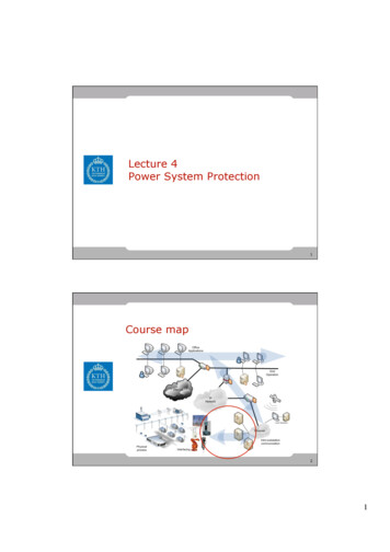
Figure 6. Their output contacts will then be connected to a remote terminal unit or SCADA device toreport back to a remote operator.4800/120 V8998CVDa89CVDb CVDc2CVDa102RCVDb10To RTU2CVDc659N710Figure 6: CVD Relay ConnectionsThe operation of the protection scheme designed above will be tested for each fault type usingASPEN. Since OneLiner deals with power system voltages and does not directly simulate controlvoltages such as that of a VT secondary, the turns ratio is factored in to compare hand calculation resultsto those of the simulation. While the development of Equation 1 for a single line-to-ground fault waspreviously provided in the background, hand calculations for other fault types in the ungrounded systemare attached in Appendix II. These calculations provide the expected relay voltages for other faults typesto be compared with ASPEN results. The following section presents the resulting VT phase voltages andrelay voltage for each fault scenario.ResultsThis project demonstrated the development of a protection scheme for an ungrounded system throughthe use of broken delta-connected VTs, a Basler 59N overvoltage relay, and ABB CVD relays as faultindicators. Voltages during all four types of faults were taken from the ASPEN model and are located inAppendix III. To ensure the proposed protection system would operate correctly, hand calculations wereperformed. These calculations can be found in Appendix II and a summary of the voltages is shown inTable 2 below. Although the ASPEN software does not provide a method for measuring the voltage seenby the relay, the fault voltages of the bus were confirmed to match the hand calculations.12
Table 2: Fault Voltage Hand CalculationsBased on these findings it was then determined that a Basler 59N overvoltage relay would be able todetect a single line-to-ground fault with a threshold voltage of less than 208 V, or three times the normalphase-to-neutral seen by the VTs. If the threshold were set to less than -104 V (with reversed polarityrelative to the previous case) the relay should be able to detect a double line-to-ground fault as well.Further work should test to confirm the relay’s use for this specific purpose however.In order to determine which phase is faulted, auxiliary CVD relays were connected across each phaseVT secondary. Based on the results in Table 2, the threshold for these relays to correctly trip and indicatea single faulted phase would be close to zero volts. With a negative crossing threshold set to a few voltsfor each relay, a remote operator would be able to determine which phases are faulted and distinguishbetween single line-to-ground, double line-to-ground, and three phase faults. Note, however, that theCVD voltage thresholds would have to be set higher to account for faults further out on the line, wheresome voltage drop might need to be considered between the bus and the fault.ConclusionIn summary, the ground fault protection scheme explored in this project was found to be an accuratemonitor of single line-to-ground faults in an ungrounded system and might be extended to detect doubleline-to-ground faults as well. Further, the auxiliary CVD relays are predicted to successfully to locate13
which phase(s) in the system were affected by the fault and decrease the response time for correcting thefault.Ungrounded systems are valued as providing continuous operation of medium voltage systems wherea power shutdown results in large economic losses. Although the system might continue operation with afaulted phase, ground protection is extremely important for preventing damage to critical equipment andpersonnel. While conducting research for this project it was found that most of the industry literatureavailable concentrated only on the detection of single line-to-ground faults. However, this is not the onlytype of fault that can occur within the system and as a result this project evaluated the voltages for allfault types. Lastly, methods for determining the location of the fault in the system through lamps, a signalgenerator, or fault indication relays were explored to gain insight into a fault situation and increase thereliability of the system.Recommendations for Continued WorkA proposed area for future work is the development of a lab related to the concepts discussed in thisreport. The lab would include application-based testing of the proposed overvoltage relay using labequipment. This would include determining reliability of the relay to trip for the various faults and thecoordination of the overvoltage relay with fault indicators. In addition, the lab could also includeevaluating how the system would react for varying ballast resistances values during each type of fault.14
Reference List[1] A Review of System Grounding Methods and Zero Sequence Current Sources, Basler ElectricCo., Highland, IA.[2] T. Baldwin, F. Renovich, L. Saunders, “Fault Locating in Ungrounded and High-ResistanceGrounded Systems,” IEEE Trans. Ind. Appl., vol. 37, no. 4, pp. 548-553, July/Aug 2001.[3] J. Blackburn, T. Domin, “System-Grounding Principles,” in Protective Relaying Principles andApplications, 3rd ed. Boca Raton, FL: CRC Press, 2007, ch.7, sec. 7.2-7.4, pp. 191-200.[4] Cahier technique n 190 Ferroresonance, Groupe Schnieder.[5] CVD Relay Instruction Leaflet, ABB Inc., Coral Springs, FL, 1996.[6] L. Dusang, “A Ground Fault Protection Method for Ungrounded Systems,” in 2008 IEEEElectrical Power & Energy Conference, Vancouver, Canada, 2008.[7] M. Fulcyyk, “Zero-sequence components in unit-connected generator with ungrounded neutralduring ground-faults,” in PowerCon 2000 International Conference on Power System Technology,Perth, Australia, 2000.[8] L. Gleason, “Neutral Inversion of a Single Potential Transformer Connected Line-to-Ground onan Isolated Delta System,” in AIEE Winter General Meeting, New York, NY, 1951, pp. 103-111.[9] Instruction Manual for Ground Fault Overvoltage Relay BE1-59N, Basler Electric, Highland, IL,2013.[10] D. Love, N. Hashemi, “Considerations for Ground Fault Protection in Medium-VoltageIndustrial and Cogeneration Systems,” IEEE Trans. Ind. Appl., vol. 24, no. 4, pp. 548-553, July/Aug1988.[11] W. Piasecki, et al., “Mitigating Ferroresonance in Voltage Transformers in Ungrounded MVNetworks,” IEEE Trans. Power Del., vol. 22, no. 4, pp. 2362-2369, Oct 2007.[12] The 59N and Broken Delta Applications, Basler Electric Co., Highland, IA, 2013.[13] V. Valverde, et al., “Behavioral Patterns in Voltage Transformer for Ferroresonance Detection,”Elec. Eng. Dept., E.T.S.I.I, Univ. of Basque Country, Bilbao, Spain, 2012.[14] V. Valverde, et al., “Ferroresonance in Voltage Transformers: Analysis and Simulations,” Elec.Eng. Dept., E.T.S.I.I, Univ. of Basque Country, Bilbao, Spain.15
Appendix I: Journal ReviewCurrently, the common ground fault detection methods being used for ungrounded systems are able todetect the presence of a ground fault but do not provide information about the location of where the faultoccurred. The article “Fault Locating in Ungrounded and High-Resistance Grounded System” focuses ondetecting and locating ground faults in ungrounded and high resistance grounded systems.For an ungrounded system the fault current is too low for a current monitoring relay to effectivelydetect the fault. As the authors state there are many ways to detect a ground fault in the system, such asindicator lights connected to each phase, voltmeters, and voltage relays. However, these methods onlydetect the phase on which the fault occurred and not where the fault was physically located within thesystem. The first proposed location method includes the installation of a zero-sequence signal generator.When a ground fault is detected the associated relay initiates the signal generator to supply a currentthrough the system that loops back through the grounding network once it reaches the fault. The signalgenerator is then able to determine the electrical distance from the relay to the fault. To avoidcommunication problems with other equipment the frequency selected for the signal generator is differsfrom the power line carrier frequency. Another location method utilizes remote ground-fault indicators(RGFI). The RGFIs are connected to the zero sequence current of a transformer. When a line-to-groundfault occurs the RGFI detects a current through the zero sequence and then provides a physical indicationof where the fault occurred. Both location methods were tested for an ungrounded delta connectednetwork and high-resistance network. Although there was error in the measurements the article estimatesthat roughly 240 hours of work were saved by implementing these location schemes.Being able to locate a ground fault in a complex system would greatly reduce the service time neededfor ground faults in an ungrounded system. One aspect of the first method of location that could beexpanded on more is how the relay and the signal generator would be coordinated. For example, futurework could address how the signal generator is integrated in relay’s tripping scheme. Also, for methodtwo the authors could look into the benefits of connecting the RGFI to a SCADA system so that thelocation of the fault is recorded. This would help determine if there is another underlying problem in thesystem causing the ground faults thus increasing system reliability.Overall, this article effectively discussed the basic concepts behind ground fault protection inungrounded systems including the authors’ ideas for locating faults. Some areas of future expansion areadding more industry testing and methods for decreasing the location error. Currently, a utility may notutilize these location methods due to the cost of adding the signal generators or RGFIs. However, this is amethodology that could be beneficial when applied to large systems requiring continuous operation.16
1152IEEE TRANSACTIONS ON INDUSTRY APPLICATIONS, VOL. 37, NO. 4, JULY/AUGUST 2001Fault Locating in Ungrounded and High-ResistanceGrounded SystemsThomas Baldwin, Member, IEEE, Frank Renovich, Jr., Member, IEEE, Lynn F. Saunders, Fellow, IEEE, andDavid Lubkeman, Senior Member, IEEEAbstract—One of the most common and difficult problems tosolve in industrial power systems is the location and eliminationof the ground fault. Ground faults that occur in ungrounded andhigh-resistance grounded systems do not draw enough current totrigger circuit breaker or fuse operation, making them difficultto localize. Techniques currently used to track down faults aretime consuming and cumbersome. A new approach developedfor ground-fault localization on ungrounded and high-resistancegrounded low-voltage systems is described. The system consistsof a novel ground-fault relay that operates in conjunction withlow-cost fault indicators permanently mounted in the circuit. Theground-fault relay employs digital signal processing techniquesto detect the fault, identify the faulted phase, and measure theelectrical distance away from the substation. The remote faultindicators are used to visually indicate where the fault is located.The resulting system provides a fast, easy, economical, and safedetection system for ground-fault localization.IndexTerms—Ground-faultgrounding, ungrounded system.location,high-resistanceI. INTRODUCTIONUNGROUNDED and high-resistance grounded industrialpower systems have a great advantage; they can operateindefinitely with a ground fault on one phase, eliminating theneed for an immediate shutdown. Once the fault is located, theparticular circuit can be isolated and the fault cleared at a convenient time, resulting in a controlled, minimized outage. Thisadvantage has tremendous value in many industries, where theinstantaneous tripping of faulted circuits to critical processeswould result in losses of production, materials, and equipment[1]–[3].A major problem in operating these systems is locating aground fault when it occurs. The search may be difficult andtime consuming. For one particular manufacturing site studied,approximately half of the faults were quickly located; the otherfaults required on average four man-hours, and a few faultsPaper PID 01–24, presented at the 2000 IEEE Petroleum and ChemicalIndustry Technical Conference, San Antonio, TX, September 10–14, and approved for publication in the IEEE TRANSACTIONS ON INDUSTRY APPLICATIONSby the Petroleum and Chemical Industry Committee of the IEEE IndustryApplications Society. Manuscript submitted for review September 15, 2000and released for publication May 11, 2001.T. Baldwin is with FAMU-FSU, Tallahassee, FL 32306 USA (e-mail:tbaldwin@eng.fsu.edu).F. Renovich is with General Motors Corporation, Parma, OH 44130 USA(e-mail: frank.renovichjr@gm.com).L. F. Saunders is with General Motors Corporation, Detroit, MI 48202 USA(e-mail: lynn.saunders@gm.com).D. Lubkeman is with ABB Power T&D Company, Raleigh, NC 27606 USA,(e-mail: david.lubkeman@us.abb.com).Publisher Item Identifier S 0093-9994(01)06309-5.took 16 or more hours. Small-magnitude fault currents flow inthe faulted network due to the leakage (or grounding) capacitance and through the grounding resistor if one is present. Thesystem leakage capacitance is distributed throughout the entirenetwork. It acts as if it were a single lumped capacitance; however, the charging currents can be observed flowing in all branchcircuits. Typical fault currents are less than 10 A.A. Ground-Fault ProtectionThe original intent of ungrounded systems was to keep thepower system operating after the first indication of a groundfault. System maintenance personnel were responsible forlocating and correcting the problem before a second groundfault could occur on another phase. When done efficientlyand quickly, this approach allows the power system to havenearly continuous operation under most situations. Fault repairscould be conducted during normally scheduled shutdowns. Theimmediate removal of power to a faulted section upon detectionof the first fault defeats the main advantage of high-resistancegrounded and ungrounded systems.Detecting the presence of a ground fault is simple. Techniques using indicator lights, voltmeters, and voltage-sensitiverelays have been applied for many years. When one
The ground fault protection scheme developed involves an overvoltage relay, connected across broken delta-connected VTs, that monitors zero sequence voltage. . (VT) connected in wye-grounded to broken-delta configuration and a Basler 59N overvoltage relay. Relay settings and configuration for the overvoltage relay will be determined, as well .