Transcription
Omaha, NBOctober 12, 2017Advanced GeneratorGround Fault ProtectionsA Revisit with New Information72nd Annual Conference forProtective Relay EngineersMarch 25-28, 2019Wayne HartmannBeckwith ElectricSenior VP, Customer ExcellenceSenior Member, IEEE
Speaker BioWayne HartmannSenior VP, Customer 44Beckwith Electric’s top strategist for delivering innovative technologymessages to the Electric Power Industry through technical forums andindustry standard development. Before joining Beckwith Electric, performed in application, sales and marketing managementcapacities at PowerSecure, General Electric, Siemens Power T&D and Alstom T&D.Provides strategies, training and mentoring to Beckwith Electric personnel in sales, marketing,creative technical solutions and engineering.Key contributor to product ideation and holds a leadership role in the development of coursestructure and presentation materials for annual and regional protection and control seminars.Senior Member of IEEE, serving as a Main Committee Member of the Power System Relaying andControl Committee for more than 25 years.Chair Emeritus of the IEEE PSRCC Rotating Machinery Protection subcommittee (’07-’10).Contributed to numerous IEEE Standards, Guides, Reports, Tutorials and Transactions, deliveredTutorials IEEE Conferences, and authored and presented numerous technical papers at keyindustry conferences.Contributed to McGraw-Hill's Standard Handbook of Power Plant Engineering.2
Introduction Ground faults in generator stator andfield/rotor circuits are serious events that can:– Lead to Damage– Cause Costly Repair– Result in Extended Outage– Cause Loss of Revenue We will examine traditional and advancedprotection3
Field/Rotor Ground Fault Damage Initial field/rotor circuit ground establishesground reference– In the event of a second ground fault,part of the field/rotor circuit is shorted out Shorted portion of rotor causes unequal flux in air gapbetween rotor and stator Unequal flux in air gap causes torsional stress and vibration,and can lead to considerable damage in rotor and bearings In extreme cases, rotor contact with stator is possible– Second rotor ground fault produces rotor iron heatingfrom unbalanced currents Field/rotor ground faults should be detected andaffected generators alarmed at high resistancelevels and tripped at low resistance levels4
Field/Rotor Ground Fault Traditional field/rotor circuitground fault protection schemesemploy DC voltage detection– Schemes based on DC principles are subjectto security issues during field forcing,other sudden shifts in field current andsystem transients5
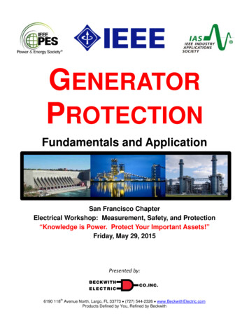
Brushed and “Brushless” Excitation“Brushless”Brushed6
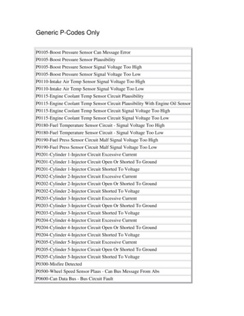
Brushes and Collector RingsHPC Technical & National Coil7
Field/Rotor Ground Fault (64F) To mitigate security issues of traditionalDC-based rotor ground fault protectionschemes, AC injection-based protectionmay be used– AC injection-based protection ignoreseffects of sudden DC current changesin field/rotor circuits andattendant DC scheme security issues8
DC-Based 64F9
Advanced AC Injection MethodFieldExciterBreaker Square WaveGeneratorExciter–SignalMeasurement& ProcessingProtectiveRelayCouplingNetwork10
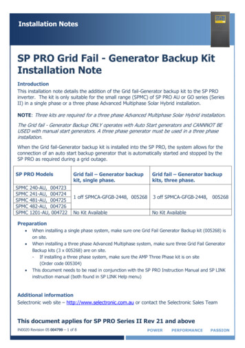
Generator ProtectionRotor Ground Fault Measurement§ Plan a shutdown to determine why impedance is lowering, versus aneventual unplanned trip!§ When resistive fault develops, Vf goes rement PointFIELD NG NETWORKC37C35SIGNALMEASUREMENTCIRCUITVf36Time RRRGEN.ROTORRf Cf,MachineFrameGroundShaftGround Brush11
Generator ProtectionBrush Lift-Off Measurement§ When brush lifts off,Vf goes upBrush Lift-OffVoltageVf ment PointVNORMAL Normal Voltage forHealthy Brush ContactVALARM PROCESSORFIELD NG NETWORKC37C35SIGNALMEASUREMENTCIRCUITTimeVf36Alarm Voltage when BrushResistance Increases dueto poor contact RRRGEN.ROTORRf Cf,MachineFrameGroundShaftGround Brush12
Advanced AC Injection Method:Advantages Scheme is secure against effects of DC transients infield/rotor circuit– DC systems are prone to false alarms and false trips,so they sometimes are ignored or rendered inoperative,placing generator at risk– AC system offers greater security so this important protectionis not ignored or rendered inoperative Scheme can detect grounding brush lift-off based onchange in rise time of the injected signaldue to disconnection of the rotor capacitance– In brushless systems, measurement brush may be periodicallyconnected for short time intervals– Brush lift-off function must be blocked during time intervalmeasurement brush is disconnected13
Stator Ground Fault Ground faults in stator winding can cause severe damageas level of fault current increases– Depending on ground fault current available,damage may be repairable or non-repairable Generators are subject to prolonged exposureto stator ground fault damage due to the fact that even ifsystem connection and excitation are tripped, stored fluxremains and contributes to arc as generator coasts down Due to exposure to this damage, several types ofgenerator grounding are employed– Stator circuit of generator may be ungrounded,low-impedance grounded, high-impedance grounded orhybrid-impedance grounded14
The Problem with Clearing Generator Ground FaultsISystemIGenGISystemCurrentIGen Current Decay0GeneratorBreaker TripsTimeXPowerSystem
Stator Ground Fault DamageOverexcitation causing insulation damageand subsequent ground fault16
Generator GroundingUngroundedResistance GroundedHigh-Impedance lGroundingResistorGSystemGSUTransformer17
Generator GroundingHybrid Impedance Grounded18
Stator Ground Fault Traditional stator ground faultprotection schemes include:– Neutral overvoltage– Various third harmonicvoltage-dependent schemes These exhibit sensitivity, securityand clearing speed issues that maysubject generator to prolongedlow level ground faults that mayevolve into damaging faults19
Neutral Overvoltage (59G)90-95% CoverageSystemNGTGSU Transformer59GNGR 59G provides 95% stator winding coverage20
59G System Ground Fault Issue90-95% CoverageCapacitive Coupling onSystem Ground FaultSystemNGT59G-1GSU Transformer59G-2NGR GSU provides capacitive coupling for system ground faults intogenerator zone Use two levels of 59G with short and long time delaysfor selectivity Cannot detect ground faults at/near neutral(very important)21
Multiple 59G Element Application59G-18V, 80 cyc.Time (cycles)90Trip 59G-14559G-215V, 10 cyc.Trip 59G-205101520 Volts 59G-2 is blind to capacitive coupling by GSU– Short time delay (18V in work up) 59G-1 is set to 8V, which may include effects of capacitivecoupling by GSU (12V in work up)– Long time delay22
Why Do We Care AboutFaults Near oundingResistorGSUTransformer A fault at or near neutral shunts high resistance that savesstator from large currents with internal ground fault A generator operating with undetected ground faultnear neutral is an accident waiting to happen Neutral undervoltage (3rd Harmonic) orInjection Techniques for complete (100%) coverage is used23
3rd Harmonic Undervoltage (27TN)0-15% CoverageNGT59GGSU Transformer27TN59NGR Fault near neutral shunts 3rd harmonic near neutral to ground Result is third harmonic undervoltage Security issues with generator operating mode and poweroutput (real and reactive)25
3rd Harmonic Ratio or Difference (59R or 59D) Fault near neutral or terminal shunts 3rd harmonic– This upsets difference or ratio between neutral or terminal ends of statorReliability may be issue with low levels of 3rd harmonic(element blocks with low values)Security issues with generator operating mode and power output(real and reactive) as that can change ratios in unpredictable ways26
3rd Harmonics at Neutral Variations with LoadingExample Plot on Gas Turbine (Midsize, 180MVA)27
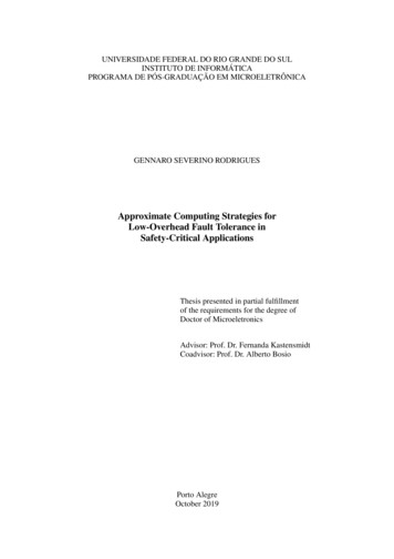
Use of Symmetrical Component Quantitiesto Supervise 59G Tripping SpeedI2 0.05 puNOTES:[A] 59N-1 is set sensitive andfast, using I2 supervision tocheck for external ground faultsand control (block) the elementfor external ground faults[B] 59N-2 is set less sensitiveand slower, therefore it will notoperate for external groundfaults.Block59N-1 [A]§ Setting§ TimeTrip59N-159N-2§ Setting§ TimeV2 0.05 pu[D]V0 0.07 puANDORTrip59N-2Block60FL Asserts59N-1 [A]NOTES:§ Setting§ Time[A] 59N-1 is set sensitive and fast,using V2 and V0 supervision tocheck for external ground faultsand control (block) the element forexternal ground faultsBlock[B][C][B] 59N-2 is set less sensitive andslower, therefore it will not operatefor external ground faults.[C] V2 derived from 3Y phase VTs[D] V0 derived from 3Y phase VTsTrip59N-1Block59N-2 [B]§ Setting§ TimeTrip59N-2 Both V2 and I2 implementation have been applied– A ground fault in generator zone produces primarily zero sequence voltage– A fault in VT secondary or system (GSU coupled) generates negativesequence quantities in addition to zero sequence voltage28
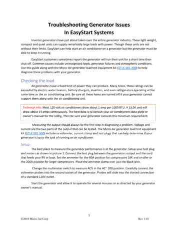
Stator Ground Fault DamageTypical windingdamage resulting frombroken stator windingconductorTypical core andwinding damageresulting from a burnedopen bar in a slotTypical windingdamage resulting frombroken stator windingconductorClyde V. Maughan; “Stator Winding Ground Protection Failures,” ASME Power 201329
Intermittent Arcing Ground Faults Can be very destructive, especially at neutral At neutral, even though AC current is very low, arcing faultdevelops a high voltage DC transient If enough arcs occur in a short time, destructive insulation damagecan occur Conventional time delayed ground fault protection cannot protectfor these eventsBurned away copper ofa fractured connection ringSide of a bar deeply damagedby vibration sparkingPremature Failure of Modern Generators, Clyde V. Maughan30
Intermittent Arcing Ground FaultVABVBCVCAVNIN31
Intermittent Arcing Fault Timer lable Trip Timer: Times Out to TripIntegrating Reset Time: Delays Reset for Interval32
Intermittent Arcing Ground FaultTRIP108Stalling TripTimer(cycles)6420Arcing Fault Detected(cycles)113221Master Reset Timer(cycles)010Arcing and Trip2033
Intermittent Arcing Ground Fault108Stalling TripTimer(cycles)6420Arcing Fault Detected(cycles)11Master Reset Timer(cycles)010Arcing and Reset (No Trip)2034
Intermittent Arcing Ground Fault Turned Multiphase35
Arcing Ground Fault Detection59G/27TN Timing Logic59G pu spInterval TimerO27TN pu spAV1 80%Delay TimerININOUT5 cyclesPick Up10 cyclesDrop OutOUTTrip59G/27TNArcing3 cyclesInterval and Delay Timers used together todetect intermittent pickups ofarcing ground fault36
Subharmonic Injection: 64SNatural Capacitance 20Hz injected intogroundingtransformersecondary circuit Rise in realcomponent ofinjected currentsuggests resistiveground fault Ignores capacitivecurrent due toisophase bus andsurge capsCoupling FilterVoltageInjectorV20HzINotes:Ø Subharmonic injection frequency 20 HzMeasurementsØ Coupling filter tuned for subharmonic frequencyØ Measurement inputs tuned to respond to subharmonic frequency37
Subharmonic Injection: 64S§§§NeutralGroundingTransformerNo V0, therefore no I0No current flow through neutralNo interference with 20Hz injected istorStatic FrequencyConverter Functions on-line and off-line Power and frequency independent38
Arcing Ground Fault Detection59G/64S Timing Logic59G pu spInterval TimerODelay TimerININOUT64S pu sp5 cyclesPick Up10 cyclesDrop Out3 cyclesOUTTrip by59G/64STransientGroundFaultProtectionInterval and Delay Timers used together todetect intermittent pickups ofarcing ground fault39
Subharmonic Injection: 64SSecurity Assessment Real component:Used to detect and declare stator ground faultsthrough entire stator winding (and isophase and GSU/UATwindings), except at the neutral or faults with very low(near zero) resistance. Total component:A fault at the neutral or with very low resistance resultsin very little/no voltage (VN) to measure, thereforecurrent cannot be segregated into reactive and realcomponents, so total current is used as it does not requirevoltage reference. In addition, presence of total current provides diagnostic checkthat system is functional and continuity exists inground primary and secondary circuits.40
Subharmonic Injection: 64SSecurity Assessment A typical stator resistance (not reactance) to ground is 100k ohm, and a resistive fault in the stator istypically declared in the order of 5k ohm. The two areas of security concern are when thegenerator is being operated at frequencies of20 Hz and 6.67 Hz. All other operating frequenciesare of no concern due to the 20 Hz filter andtuning of the element response for 20 Hz values. For our analysis, we use data from a generator in thesoutheastern U.S.A. outfitted with a 64S, 20 Hzsubharmonic injection system.41
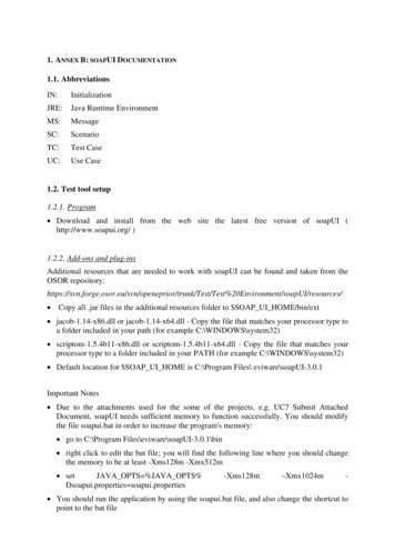
Subharmonic Injection: 64SSecurity AssessmentNatural CapacitanceCase 1: Generator Operating at20 Hz If the generator is operating as agenerator at 20 Hz without anexternal source (e.g., drive, LCI,back-to-back hydro start), there is noconcern as the 20 Hz at the terminalsis at or very close to balanced;therefore, 20 Hz zero-sequencecurrent will not flow through theneutral circuit.If the generator is being operated asa motor with an external source(e.g., drive, LCI, back-to-back hydrostart), the phase voltages arebalanced or very close to balanced.343 MVA20kVCoupling 00 :5INotes:Ø Subharmonic injection frequency 20 HzMeasurementsØ Coupling filter tuned for subharmonic frequencyØ Measurement inputs tuned to respond to subharmonic frequency42
Subharmonic Injection: 64SSecurity AssessmentObservations:Real Ω 118kΩTotal Ω 23kΩ43
Subharmonic Injection: 64SSecurity AssessmentCalculate CT primary currents:IN pri (total) 14.1 A * 10-3 * CTRIN pri (total) 14.1 A * 10-3 * 80IN pri (total) 1.128AIN pri (real) 2.8 A * 10-3 * CTRIN pri (real) 2.8 A * 10-3 * 80IN pri (real) 0.224 ACurrents and voltages atgrounding transformer primary:IN pri (total) 1.128 A / NGT ratioIN pri (total) 1.128 A / 83.33IN pri (total) 0.013536 AIN pri (real) 0.0224 A / NGT ratioIN pri (real) 0.0224 A / 83.33IN pri (real) 0.002688 AVN pri V sec * NGT ratioVN pri V sec * NGT ratioVN pri 25 V3rd harmonic voltage measured at relay 0.75 VVVVpripripri V sec * NGT ratio 0.75 V * 83.33 62.5 VAssuming a zero sequence unbalance of 0.1% of nominal at 60HzVVVVVVpri unbalancepri unbalancepri unbalancesec unbalancesec unbalancesec unbalance % unbalance / 100 * V L-L rated / 3 (0.1% / 100) * (20,000 V / 1.73) 11.5V V pri unbalance / NGT ratio 11.5 V / 83.33 0.14 VAssuming V/Hz is kept constant in LCI or back-to-backgenerator start. The voltage at 20 Hz frequency is20 Hz voltage during the start.Assuming 1pu V/Hz 120/60 2 1pu Frequency divisor: 60 Hz / 20 Hz 3. Voltage divisor is 3.V sec unbalance (20 Hz) V sec unbalance (60 Hz) / 3V sec unbalance (20 Hz) 0.14 V / 3 0.0466 V44
Subharmonic Injection: 64SSecurity Assessment20 Hz current flowing through NGR:NGR I 20 Hz V sec unbalance (20 Hz) * NGR ΩNGR I 20 Hz 0.0466 / 0.2 0.223 ASettings:Real Ω 55kΩTotal Ω 16kΩRelay measured 20 Hz current:I 20Hz Relay NGR I 20 Hz * CTRI 20Hz Relay 0.223 A / 80I 20Hz Relay 0.0029 A 2.9 mAUsing pickup values are 20 mA total and 6 mA real, element remains secure. Note the margins:Total current calculated: 2.9 mATotal current calculated: 2.9 mATotal current setting: 20 mAReal current setting: 6.0 mA45Margin: 17.1 mAMargin: 3.1 mA
Subharmonic Injection: 64SSecurity AssessmentCase 2: 6.67 Hz voltage at the generator terminals,assume 3rd harmonic (20 Hz) created in the neutralIn this case, we are assuming the generator under study is being started with adrive, LCI or back-to-back hydro start. The generator is acting like a motor andthe unbalance is originating from the source.Using typical values from a generator operating under full load,3rd harmonic can be expected to be approximately 5X no load value.3rd V 60 Hz NGT pri 5 * (no load 3rd harmonic) * NGT ratio3rd V 60 Hz NGT pri 5 * 0.75 V * 83.333rd V 60 Hz NGT pri 312.498 VThe frequency during the start is reduced to 6.67 Hz (3 * 6.67 Hz 20 Hz).Assuming the V/Hz is kept as constant, the 3rd harmonic voltage is reduced.3rd V 20 Hz NGT pri 6.67 Hz / 60 Hz * 312.498 V(without reduction in capacitance)3rd V 20 Hz NGT pri 34.74 V (without reduction in capacitance)46
Subharmonic Injection: 64SSecurity AssessmentSince the frequency is 20 Hz and not 180 Hz, there is a further reductionin 3rd harmonic current due to the capacitance at 1/9th of 60 Hz value.(180/20 9)The model is complex and the relationship is not straightforward,so we assume a reduction of 1/5th instead of 1/9th3rd V 20 Hz NGT pri 34.74 V / 5 6.9 VVoltage at NGT secondary:NGT V sec 3rd V 20 Hz NGT pri / NGT ratioNGT V sec 6.9 V / 83.33 0.0828 VCurrent through NGR:NGR I 20 Hz NGT V sec / NGR ΩNGR I 20 Hz 0.0828 / 0.2 0.414 ARelay measured 20 Hz current:I 20Hz Relay NGR I 20 Hz * CTRI 20Hz Relay 0.414 A / 80I 20Hz Relay 0.005175 A 5.175 mA47
Subharmonic Injection: 64SSecurity AssessmentNote the margins: Total current calculated: 5.175 mATotal current setting: 20 mAMargin: 14.825 mA Total current calculated: 5.175 mAReal current setting: 6.0 mAMargin: 0.825 mAHigher Margin for Real Ω: 7.0mA 47.2kΩ; 8.0mA 41.3kΩ48
Summary and Conclusions Field/Rotor Ground Fault– Use of AC injection offers greater security than traditional DCmeasurement systems, and can also detect brush lift-offcondition 95% Stator Ground Fault Protection– Use of 59G element is time-tested method of protecting 95% ofstator for generator ground faults Traditional approach to cope with GSU capacitive coupling andinterference with 59G element is using two elements, one long withlong time delay coordinated system ground protection, and otherwith short time delay for in-zone ground faults. An advanced method of using sequence component supervisionallows determination of external ground faults, and allows 59Gelement to quickly clear ground faults in generator zone.49
Summary and Conclusions 100% Stator Ground Fault Protection– 3rd harmonic protection implementations are available tocomplement 59N element to provide 100% stator ground faultprotection. 3rd harmonic protections may not work with all generators, andmay not work at all times on given generator. 3rd harmonic values available for protection vary with operationalmode and power (real and reactive) output.– Both security and dependability issues may develop.– Intermittent arcing ground faults can be detected with use ofinterval timing scheme on 59G and 27TN protections. This enhancement provides the ability to detect intermittentground faults before a permanent ground/multi phase faultdevelops.50
Summary and Conclusions 100% Stator Ground Fault Protection– Use of subharmonic injection provides ability to detectground faults anywhere in stator or in unit-connectedzone regardless of generator operation and loading– If element uses real component for fault declaration,it is very sensitive– As long as external signals at or near the subharmonicinjected frequency are balanced, element is highly secure Element only responds to zero sequence current in generatorneutral, not positive sequence current from external balancedsystem such as:– Another generator during back-to-back starting– Static converter employed in starting combustiongas turbine generators51
References1. IEEE Guide for Generator Ground Protection, ANSI/IEEE C37.101-2006.2. IEEE Guide for AC Generator Protection, ANSI/IEEE C37.102-2006.3. IEEE Tutorial on the Protection of Synchronous Generators, Second Edition,2010; Special Publication of the IEEE Power System Relaying Committee.4. IEEE Recommended Practice for Grounding of Industrial and CommercialPower Systems, IEEE Std. 142-1991.5. Protection Considerations for Combustion Gas Turbine Static Starting; WorkingGroup J-2 of the Rotating Machinery Subcommittee, Power System RelayingCommittee.6. Protective Relaying for Power Generation Systems; Donald Reimert, CRC Press2006; ISBN#0-8247-0700-1.7. Practical Improvement to Stator Ground Fault Protection Using NegativeSequence Current; Russell Patterson, Ahmed Eltom; IEEE Transactions Paperpresented at the Power and Energy Society General Meeting (PES), 2013 IEEE.8. Behavior Analysis of the Stator Ground Fault (64G) Protection Scheme; RamónSandoval, Fernando Morales, Eduardo Reyes, Sergio Meléndez and Jorge Félix,presented to the Rotating Machinery Subcommittee of the IEEE Power SystemRelaying Committee, January 2013.52
Omaha, NBOctober 12, 2017Advanced GeneratorGround Fault ProtectionsA Revisit with New InformationWayne HartmannBeckwith ElectricSenior VP, Customer ExcellenceSenior Member, IEEEQuestions?
[A] 59N-1 is set sensitive and fast, using V. 2. and V. 0. supervision to check for external ground faults and control (block) the element for external ground faults [B] 59N-2 is set less sensitive and slower, therefore it will not operate for external ground faults. [C] V. 2. derived from 3Y phase VTs [D] V. 0. derived from 3Y phase VTs. Trip .