Transcription
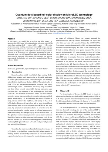
Quantum dots based full-color display on MicroLED technologyCHIH-HAO LIN1, CHUN-FU LEE1, CHIEN-CHUNG LIN2, CHEN-HSIEN CHU2,CHIN-WEI SHER3, ZHAO-JUN LIU4, AND HAO-CHUNG KUO1,*1Department of Photonics and Institute of Electro-Optical Engineering, National Chiao Tung University, Hsinchu 30010,Taiwan2Institute of Photonic System, National Chiao Tung University, Tainan 711, Taiwan3Fok Ying Tung Research Institute, Hong Kong University of Science and Technology, Hong Kong4Department Of Electrical and Electronic Engineering, Southern University of Science and Technology, Shenzhen, China*Corresponding author: hckuo@faculty.nctu.edu.twAbstractIn this paper, we would like to review our lab's result " aquantum-dot (QD)-based full-color emission red–green–blue (RGB)micro-light-emitting-diode(micro-LED)array". By usingphotoresist as the masking material for micro-LED arrays, also thephotoresist mold can reduce optical cross-talk effect. The colloidalquantum dots (QDs) are used as photon conversion layer and theAerosol Jet technology was applied for dispensing the QDs. Afull-color array can be demonstrated and the isolation betweenpixels can be improved. The output light intensity can also beimproved via the inclusion of a ultra-violet band distributed Braggreflector (DBR).Author Keywordsmicro LED, quantum dot, light emitting diode, micro display1.IntroductionRecently, gallium-nitride-based (GaN) light-emitting diodes(LEDs) have attracted much attention due to their wide applicationin visible light communications, vehicle headlights, and backlightunits (BLU) in liquid crystal displays (LCDs). The main benefits ofGaN LEDs are low-power-consumption, low-cost, and highlyluminous light source. Furthermore, now a day, many researchersput their efforts towards micro-LEDs having micrometer-scale( 100μm) size. The advantage of this technology over large-scale(scale of a few hundred micrometers) LEDs are their differentproperties such as high current density operation and as a result highoptical power density [1]. By fabricating the micro-LEDs into anarray, one can improve the brightness, and quality of BLU in anLCD display. However, it is a tedious task to grow three differentlight emitting units such as red–green–blue (RGB) on the samepanel. by epitaxial or fabrication efforts. In order to solve thisproblem, an alternative emitting source of colloidal quantum dots(QDs) and exciting the QDs optically by the LEDs can be used. [2].The QDs have various unique properties such as narrow emissionlinewidths, large-area color gamut and high quantum yield. In ourprevious research [3], a full-color emitting panel is fabricated bycombining RGB QDs with micro-UV LEDs of 35 μm 35 μm pixelsize and in 128 128 arrays.Generally, the main reason behind efficiency loss in case ofLCD display is the backlight system. In which a large number ofemitting photons are absorb by color filter. In case of to achieveexpected optical power, it is required to operate display more thanten times of brightness. Hence, the present approach i.e.photo-luminescent (PL) QDs based micro-LEDs can replace thecolor filters and wider color gamut (1.52 times that of NTSC 1976).Color gamut was an evaluation metric, which was determined by themaximum colors in the display. Rec.2020., a new color triangle wasdevised to strictly define the color gamut standard. Our previousresearch demonstrated a QD micro display with over 80% of thecolor gamut of Rec. 2020 [4]. By accurately locating QDs on themicro-LED array by using the Aerosol Jet (AJ) technique realizessuch a QD-LED display. However, even with the optimized AJparameters in our previous test results, the cross-talk effect stilloccurred during the QD deposition because the overflow of QDswere accrued when the host solvent was evaporated. Meanwhile, thenanoparticles can be drawn towards to the edge and dropt, this calledthe “coffee ring” effect. In this research, the cross-talk effect issignificantly reduced by using Aerosol Jet printing process with thephotoresist (PR)-mold that to define the blocking wall and confineQDs field. Moreover, the addition of distributed Bragg reflector(DBR) can help UV light more effectively by re-absorption of QDs.Furthermore, the re-absorption of UV light also could prevent thehuman safety by UV exposure issues.2.Micro-LEDFor the application of display, the LED should be shrunk tomicron level to function as a pixel, and it is named as micro-LED. AsH. X. Jiang’s group in Texas Technique University had reported thefirst fabrication of micro-LED chip with diameter of 12 µm in 2001[5]. Micro-LED becomes a hot topic soon after the inception.The field of application of LEDs will vary depending on thechip size. Generally speaking, the size of the traditional LED islarger than 200 μm, the mini-LED is between 100 to 200 μm, whilethe micro-LED is smaller than 100 μm. Therefore, the traditionalLED chip is mainly used in general lighting and display backlightmodule, the mini-LED is applied to backlight applications such asHDR and flexible displays, while the micro-LED, a new displayapplication, is suitable for applications such as wearable watches,mobile phones, automotive head-up displays, AR/VR, microprojectors, and high-end televisions. Additionally, micro-LED canbe combined with a flexible substrate to realize the flexiblecharacteristics like OLED (Table 1). Therefore, micro-LED displayshave the potential to match or exceed the high contrast, low powerconsumption, high brightness of today's OLED displays without the
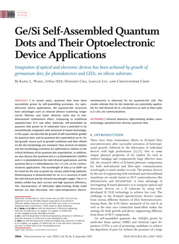
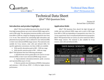
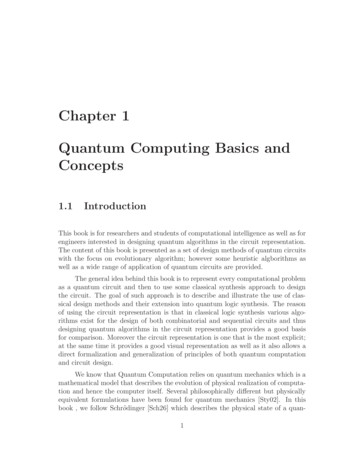
lifetime issues that are associated with organic based displaysystems.or less. Obviously, it is very difficult to transfer or grow such a hugenumber of three different micro-LEDs on the same substrate.Table 1. Requirements for mini-LED and micro-LED in typicalapplications.2.2. Color conversion of full-color displayExcitation sources (UV micro-LED or blue micro-LED) withcolor-conversion materials can be used to achieve the full-colordisplay. RGB color-conversion materials are needed to achieveRGB three primary colors if UV micro-LEDs are used, while onlyred and green color-conversion materials are required if bluemicro-LEDs are used. Generally, color-conversion materials can bedivided into the nano-phosphor and the quantum dots (QDs).Figure 3. Mechanism of color conversion full-color displayAt present, micro-LED display technology mainly faces threechallenges. First, the mass production and transfer of three-colormicro-LED chips. Second, the fabrication of TFT substrates withmicron-pixel pitch. Third, the full-color method for displayapplications. With the rapid development of technology, the firsttwo problems are expected to be effectively solved. However, howto achieve the full-color display, has become a toughest problem forthe subsequent development of Micro-LED. Next, we will discussseveral main methods of the full-color display for micro-LEDs.2.1. RGB micro-LED full-color displayThe principle of RGB full-color display is mainly based on thelaw of three primary colors that can be combined to create all othercolors in nature via a certain ratio setting. therefore, for RGB LEDs,different currents are applied to control the brightness of each LEDto realize the combination of three primary colors and achieve thefull-color display. It is the method that is usually employed in LEDlarge screens. [6].2.3. Quantum dotTo realize full-color display, colloidal quantum dots (QDs)can be a great choice. The QDs are usually synthesized by chemicalsolution process [8] and possess unique properties such as highquantum yield, size-dependent emission wavelength, and narrowemission linewidth [9,10].RGB QDs are in core-shell type structure with chemicalligands on the outer shells, and the average sizes of the QDs are 2.5nm, 6.2 nm, and 9.3 nm for blue, green, and red QDs, respectively.The absorption and emission spectra for QDs are plotted in Figure9(a), (c) and (e), while the images of the QDs in toluene under 365nm UV light excitation are shown in Figure 9(b), (d) and (f). Thewavelengths of emission spectra are 450 nm, 520 nm, and 630 nmfor blue, green, and red QDs, respectively. Moreover, due to thenarrow emission linewidths of RGB QDs, large-area color gamutcan be readily achieved.Figure 2. Mechanism of RGB micro-LED full-color display.In the RGB full-color display method, each pixel contains a setof RGB micro-LEDs. Generally, the P and N electrodes of thethree-color micro-LEDs are connected to the circuit substrate bymeans of bonding or flip-chip [7].However, the RGB micro-LED based technology suffers asevere disadvantage in mass production. For example, in order tomanufacture a 4K resolution display, nearly 25 million micro-LEDsare needed to be assembled and connected without a single error inan economical and efficient way, with placement accuracy of 1 µmFigure 4. UV-visible absorption and PL emission spectra of QDswith the emission colors of (a) blue, (c) green and (e) red. (b) blue,(d) green and (f) red are the photos of QD solution under UVexcitation.3.RESULTS AND DISCUSSIONThe micro-LED array with an emission wavelength of 395 nm,a single pixel size of 35 μm 35 μm, and a pitch of 40 μm isfabricated. The total array number is 128 128 pixels in the chiparea of 5 mm 5 mm. The UV micro-LED with RGB QDs has higherquantum yields than blue micro-LED. In order to reduce the optical
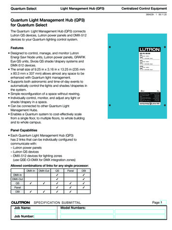
cross-talk effect, a mold with open windows and blocking walls wasfabricated with photoresist by simply lithography techniques. TheFig. 5 shows the region of the blocking wall that was formed byphotoresist and UV lithography, and the height of the PR wall is11.46 μm. The height of the blocking wall can be controlled by PRspinning processes, and we maintained it at thickness larger than10μm. A silver coating is also applied to provide further isolation orthe photon recycling.Table 2 summarizes the optimized parameters which includesworking distance, carrier gas flow rate, the sheath gas flow rate, andthe stage speed for the Aerosol Jet system . During the dispense,the system will hold the working distance and the stage movingspeed at constant to reduce the number of variables. Hence, only twoparameters that we are changing here: the carrier gas flow rate andthe sheath gas flow rate. In addition, the RGB different color of QDshave different particle sizes. Also the QDs are one of thecomponents in the deposition, the different sizes of particles willaffect the deposition rate. Hence, by adjusting the carrier flow rateand the sheath gas flow rate, we are able to find the best condition forthe individual color of CQDs and obtained a good linewidth of 35μmin this study.Table 2. Parameters of the AJ Printing Technique for Different QDsFigure 5. PR square windows with pixel size 35 μm 35 μm,and the he laser scanner microscope image of the PR square wall.The Fig. 6(a) shows the process flow for such device, the UVpassive-matrix micro-LED array was fabricated on UV epi-waferswith a peak of 395 nm wavelength and a pitch size of 40 μm. The128 128 pixels micro-LED pixels fabricated in the same columnand sharing a common electrode of the n-type GaN. All of the stripesof the micro-LED array have been created individually by dryetching of GaN down to the sapphire substrate. On the dry etchingprocess, SiO2 was used as the hard mask. Finally, the p-electrodestripes were placed on top of the chips, and the n-electrode stripeswere placed on the n-GaN layer, and all of the pixels are connectedin the same row. The windows of the PR mold can be properlyaligned to the micro-LED array, as shown in Figs. 6(b)–6(e), the AJRGB QDs can be effectively deposited on the mold region, alsoprevent RGB QDs accrued overlay issue by the trench of PR wall. Inorder to fit the window size, the printing parameters are optimized.The adjustable parameters include the working distance between thenozzle and the substrate.Figure 6. Process flow of the full-color micro display. (a) Thestructure of the micro-LED arrays. (b) Aligning the mold to the UVmicro-LED array. (c)–(e) The process flow of the aerosol jetprinting of RGB QDs on micro-LED array. (f) Coating Al2O3 ALDlayer.After we deposit the CQDs onto the molded glass substrateand align to the micro-LED array, the processes are finished. TheFig. 7 shows the different examples with and without molding wallscan be shown. Both under regular OM and fluorescence OM can beseen, we find the intended channel is about 40.2 μm as mentioned inFig. 7(a). Beside this, Fig. 7(b) show the overlap area of the red lineis about 13.4 μm (the deviation between 53.4 and 40.2 μm). Theblurred boundary between each color sub-pixel shows the possibleleakage of photons into the other color and thus become the opticalcross-talk. The cross talk can be defined as the photons astray intothe neighboring pixels:Crosstalk(%) ��𝑒𝑑 𝑐ℎ𝑎𝑛𝑛𝑒𝑙 100%(1)where “Leakage” is the luminance of light that leaks from theunintended channel to the intended channel, which is defined as theoverlap area. This method is largely based Wood’s research [11].From the comparison of the light field distribution in Fig. 3, wecould find that the molded case has almost all the colors containedwithin the pixel range, while the no-molding case has about 32.8%light distribution extended to next pixels.Figure 7. (a) Intended channel of the micro-LED layout with thepitch of 40.2 μm. (b) The previous result of cross-talk issue bywithout PR mold pixel array. (c) Observed the pixel array with PRmold by fluorescence microscopy.
In addition, this study resolves the coffee ring effect by the PRmold layer on micro-LED. The significant coffee ring effect thatmeans QDs particle droplet and deposit along the surface tension tothe edge when the host solvent was evaporated. Meanwhile, thenanoparticles can be drawn towards the boundary region, and thiscalled the “coffee ring” effect as shown in Fig. 8(a) However, if wemust to maintain the nanoparticles’ feature without shrinkage issue,such a Nano-rippled surface exhibits hydrophobic characteristicsand can be used to concentrate the droplets on the target area with alarger contact angle [12]. Hence, we demonstrate the walled pixelcase (Fig. 4b), the wall formed a three-dimension container whichcan distribute the particle more evenly during the evaporationprocess such that the afterward distribution of CQDs are muchuniform than before. This is more favorable than the regularno-molding case. [13–15].spectra reveal that the QDs enhanced the throughput about 23%,32%, and 5% for red, green, and blue, respectively. The lowerincrease rate in blue band caused by the residual reflectance in theblue region of the DBR, which can cause the re-direct of the bluephotons but lead to the extra loss. This can be further improved byoptimized the DBR layer stack with a layer thickness of λ (4n cosθ).Figure 9. The measured EL spectra of RGB QDs on a UVmicro-LED array, where the black and blue lines represent thedevices with and without the DBR, respectivelyFigure 8. (a) The scheme of the coffee ring effect as show theoutward flow issue caused by QDs evaporation loss. (b) Thescheme of the PR mold design reduces the coffee ring effect.Furthermore, the distributed Bragg reflector (DBR) techniquewill be an important applied on LED that to increase the UV lightutilization by obtain a highly reflective interface to recycle thepumping photons. Regarding the DBR structure was composed ofmultiple pairs with different refractive index layer, we used theregular formula as follows [16, 17], where λ is the selectedwavelength, the thickness d of the stacking dielectric materialsdepends on the refraction index and incidence angle θ, m is thenumber of stacked layers, and nsub, n1, and n2 represent therefractive indices of the substrate and the stacking dielectric layers,respectively. The DBR structure is prepared via alternativedeposition of 17.5 pairs of HfO2 SiO2 multilayers on a quartz glass.The measurement peak of the DBR reflectance is 92.5% and thewidth of the stop band is 80 nm.Figure 10.Light-up a row of the RGB pixelFinally, we estimate the conversion efficiency of the RGBQDs by defined the optical conversion efficiency (OCE) to calculatethe ratio of the energy transfer. To properly evaluate this number, ananalysis on the emission spectra can reveal such information. Fromthe previous study [18], we can use the following formula:(4)𝑄𝐷𝑈𝑉 𝑏𝑎𝑠𝑒𝑑where 𝐼𝑒𝑚𝑖 (𝜆) and 𝐼𝑒𝑚𝑖are the integrated emissiond λ/(4n cosθ)R 𝑟 2 (2)2𝑛𝑠𝑢𝑏 𝑛1 2𝑚( ) 1𝑛1𝑛21𝑛𝑠𝑢𝑏 𝑛1 2𝑚( ) 1𝑛1𝑛21 (3)Then we assemble the DBR on QDs-deposited LED array, themeasured of electroluminescence (EL) spectra shown in Fig. 9, theintensities in the visible band of the spectrum with and without QDs,𝑄𝐷𝑈𝑉 𝑏𝑎𝑠𝑒𝑑 (𝜆) are the integrated intensities excitedand 𝐼𝑒𝑥𝑐 (𝜆) and 𝐼𝑒𝑥𝑐by UV light with and without QDs, respectively [19,20]. Bycalculation, the conversion efficiencies of the blue, green, and redCQDs layer are represent 2.25%, 10.8%, and 6.9%, respectively.The reason for the lower OCE values is related a protected issueduring fabrication procedure, the efficiency of QDs would decreaseby following reason, such influence come from moisture, oxidation,and heat. We will design a protected method that to optimizereliability in the future.
4.MATERIALS AND METHODSA. Fabrication of the UV Micro-LED ArrayThe epitaxial structure of the UV micro-LED was grown bymetal organic chemical-vapor deposition, which consists of anundoped GaN buffer layer on a sapphire substrate, followed byn-GaN, a multiple quantum well with a peak emission wavelength of395 nm, p-GaN, and a current-spreading layer (CSL) for metalcontact. The UV micro-LED array was fabricated by followingprocess: mesa dry etching down to n-GaN via inductively coupledplasma (ICP), p-metal deposition on the CSL, n-metal deposition onthe n-GaN layer, and then the trench opened by ICP etching down tothe sapphire substrate that to make each micro-LED in individually,and sidewall passivation by plasma-enhanced chemical vapordeposition deposited SiO2.Figure 11. (a) the pattern of NCTU with 7.5μm linewidth.(b) observed RG QDs on Micro LED array. (c) observed the fullcolor conversion by igniting Micro LED array. (Source: SIJTechnology, Inc)Acknowledgment.The authors would like to thank the Electronic andOptoelectronic System Research Laboratories of theIndustrial Technology Research Institute and the Ministry ofScience and Technology of Taiwan and SIJ Technology, Incfor their financial and technical support.REFERENCES[1]B. AJ SystemThe aerosol system consisted of two major parts: an ultrasonicatomizer and a spraying chamber. First, the RGB QDs withconcentrations of 5 mg mL in solvent were prepared in a tube that isinside the ultrasonic atomizer, and then the suspension was atomizedby the ultrasonic vibration. The resulting AJ was consequentlytransferred to the nozzle by nitrogen gas flow. After the nitrogen gasinput, the AJ was tightly focused at the end of nozzle to producesmall drops, enabling narrow linewidth and high resolution.5.[3][4]CONCLUSIONIn conclusion, we demonstrated a full-color micro display witha combination of a UV micro-LED array, Photoresist Mold, andRGB QDs by AJ technique. The CQDs were confined by thephotoresist mold which can provide as light blocking wall and helpthe distribution of CQD more uniform. Furthermore, the opticalcross-talk effect was also reduced with PR mold. A HfO2 SiO2DBR stack can boost the efficient of UV light by recycling thepumping photons and enhanced intensity of QD emission as high asabout 32% measured. The high-quality micro displays can beachieved by these techniques. We believe this technology can behelpful for next generation of micro-display platform.6.[2]Future WorkHowever, the best scale of linewidth is 35 μm in this research.Regarding this test result, this is still insufficient good enough toachieve our objective in Micro LED field. Hence, we participatewith SIJ Technology on super inject printing project. Regarding thelatest test result, the linewidth can well control around 25 μm withsuper fine nozzle as shown in Figure 11.[5][6][7][8][9][10][11][12][13]J. Herrnsdorf, J. J. McKendry, S. Zhang, E. Xie, R. Ferreira,D.Massoubre, A. M. Zuhdi, R. K. Henderson, I. Underwood,and S. Watson, “Active-matrix GaN micro light-emittingdiode display with unprecedented brightness,” IEEE Trans.Electron Devices 62, 1918–1925 (2015).K. J. Chen, H. C. Chen, K. A. Tsai, C. C. Lin, H. H. Tsai, S.H. Chien, B. S. Cheng, Y. J. Hsu, M. H. Shih, and C. H. Tsai,“Resonant‐ enhanced full‐ color emission ofquantum‐ dot‐ based display technology using a pulsed spraymethod,” Adv. Funct. Mater. 22, 5138–5143 (2012).H.-V. Han, H.-Y. Lin, C.-C. Lin, W.-C. Chong, J.-R. Li,K.-J. Chen, P.Yu, T.-M. Chen, H.-M. Chen, and K.-M. -dot-based micro-LED display technology,” Opt.Express 23, 32504–32515 (2015).R. Zhu, Z. Luo, H. Chen, Y. Dong, and S.-T. Wu, “RealizingRec. 2020 color gamut with quantum dot displays,” Opt.Express 23, 23680–23693 (2015).Jin, S.X.; Li, J.; Li, J.Z.; Lin, J.Y.; Jiang, H.X. GaNmicrodisk light emitting diodes. Applied Physics Letters2000, 76, 631-633, 10.1063/1.125841.Geffroy, B.; Le Roy, P.; Prat, C. Organic light-emittingdiode (OLED) technology: materials, devices and displaytechnologies. Polymer International 2006, 55, 572-582,10.1002/pi.1974.Peng, D.; Zhang, K.; Chao, S.D.; Mo, W. Full-ColorPixelated-Addressable Light Emitting Diode on TransparentSubstrate (LEDoTS) Micro-Displays by CoB. Journal ofDisplay Technology 2016, 12, 742-746.Mattoussi, H.; Mauro, J.M.; Goldman, E.R.; Anderson, G.P.;Sundar, V.C.; Mikulec, F.V.; Bawendi, M.G. Self-assemblyof CdSe-ZnS quantum dot bioconjugates using anengineered recombinant protein. J. Am. Chem. Soc. 2000,122, 12142-12150, 10.1021/ja002535y.Shirasaki, Y.; Supran, G.J.; Bawendi, M.G.; Bulovic, V.Emergence of colloidal quantum-dot 23,10.1038/nphoton.2012.328.Medintz, I.L.; Uyeda, H.T.; Goldman, E.R.; Mattoussi, H.Quantum dot bioconjugates for imaging, labelling andsensing. Nature Mater. 2005, 4, 435-446, 10.1038/nmat1390.A. J. Woods, “Crosstalk in stereoscopic displays: a review,”J. Electron. Imaging 21, 040902 (2012).Guoqiang Li, Jiawen Li, Chenchu Zhang, Yanlei Hu,Xiaohong Li, Jiaru Chu, Wenhao Huang, and Dong Wu,“Large-Area One-Step Assembly of Three-DimensionalPorous Metal Micro/Nanocages by Ethanol-AssistedFemtosecond Laser Irradiation for Enhanced Antireflectionand Hydrophobicity,” ACS Appl. Mater. Interfaces 7, 383–390 (2015).R. D. Deegan, O. Bakajin, T. F. Dupont, G. Huber, S. R.
[14][15][16][17][18][19][20]Nagel, and T. A. Witten, “Capillary flow as the cause of ringstains from dried liquid drops,” Nature 389, 827–829 (1997).C. Jiang, Z. Zhong, B. Liu, Z. He, J. Zou, L. Wang, J. Wang,J. Peng, and Y. Cao, “Coffee-ring-free quantum dot thin filmusing inkjet printing from a mixed-solvent system onmodified ZnO transport layer for light-emitting devices,”ACS Appl. Mater. Interfaces 8, 26162–26168 (2016).S.-W. Wang, H.-Y. Lin, C.-C. Lin, T. S. Kao, K.-J. Chen,H.-V. Han, J.-R. Li, P.-T. Lee, H.-M. Chen, and M.-H. Hong,“Pulsed-laser micropatterned quantum-dot array for whitelight source,” Sci. Rep. 6, 23563 (2016).I. García, J. Geisz, M. Steiner, J. Olson, D. Friedman, and S.Kurtz, “Design of semiconductor-based back reflectors forhigh Voc monolithic multijunction solar cells,” in 38th IEEEPhotovoltaic Specialists Conference (PVSC) (IEEE, 2012), p.002042.H. K. H. Choy, “Design and fabrication of distributed Braggreflectors for vertical-cavity surface-emitting lasers,” inIEEE International Conference on SemiconductorElectronics (Citeseer, 1998).K. Suzuki, A. Kobayashi, S. Kaneko, K. Takehira, T.Yoshihara, H. Ishida, Y. Shiina, S. Oishi, and S. Tobita,“Reevaluation of absolute luminescence quantum yields ofstandard solutions using a spectrometer with an integratingsphere and a back-thinned CCD detector,” Phys. Chem.Chem. Phys. 11, 9850–9860 (2009).S. C. Hsu, Y. H. Chen, Z. Y. Tu, H. V. Han, S. L. Lin, T. M.Chen, H. C. Kuo, and C. C. Lin, “Highly stable and efficienthybrid quantum dot light-emitting diodes,” IEEE Photon. J.7, 1–7 (2015).S.-C. Hsu, L.-A. Ke, H.-C. Lin, T.-M. Chen, H.-Y. Lin, Y.-Z.Chen, Y.-L. Chueh, H.-C. Kuo, C.-C. Lin, "Fabrication of aHighly Stable White Light-Emitting Diode withMultiple-Layer Colloidal Quantum Dots", IEEE Journal ofSelected Topics in Quantum Electronics, Vol. 23, No.5,p.1-9, 2017.
2.3. Quantum dot To realize full-color display, colloidal quantum dots (QDs) can be a great choice. The QDs are usually synthesized by chemical . PR square windows with pixel size 35 μm 35 μm, and the he laser scanner microscope image of the PR square wall. The Fig. 6(a) shows the process flow for such device, the UV