Transcription
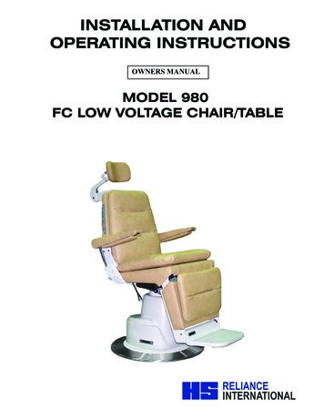
INSTALLATION ANDOPERATING INSTRUCTIONSOWNERS MANUALMODEL 980FC LOW VOLTAGE CHAIR/TABLE
SERIAL NUMBERFor your future reference, mark the serial numberin the space provided.QUALITY MANAGEMENTSYSTEMREGISTERED TOISO 9001ISO 13485MA DE IN AME R I C AReliance Medical Products 3535 Kings Mills Road Mason, Ohio 45040-2303 1-800-735-0357 www.reliance-medical.com
TABLE OF CONTENTSIMPORTANT INFORMATION.41. INTRODUCTION.5TECHNICAL SPECIFICATIONS.62. INSTALLATION.72.1. Unpacking.7Chair.72.2. Assembly.7Headrest.7Power Receptacle.7Setting Rotation Stop.73. OPERATION.83.1. Stop Switch.83.2. Chair Lift.8Raising & Lowering the Chair Lift with MembraneSwitches.8Raising & Lowering the Chair Lift from theFootswitch.83.3. Chair Top.9Raising & Reclining the Chair Top withMembrane Switches.9Raising & Lowering the Chair Top From theFootswitch.93.4. Automatic Return.103.5. Memory Feature.10Programming the Memory Feature.103.6. Revolving/Rotation.113.7. Arm Movement.113.8. Footrest.113.9. Headrest.11Operation-No. 18, 22 Headrest.11Adjustment-No. 18, 22 Headrest.12Operation-No. 10 Headrest.12Operation-No. 11, 21 Headrest.12Adjustment-No. 11, 21 Headrest.124. PROGRAMMING THE CHAIR.124.1. Safety/Shutdown Feature.12To ENTER Safety/Shutdown Mode.13To EXIT Safety/Shutdown Mode.134.2. Individual Programming of the RAISE TOP, RECLINETOP, RAISE BASE, and LOWER BASE switch located onthe Chair Back or Footswitch.13To ENTER Setup Mode .13To EXIT Setup Mode.134.3. BEEP-ON-SWITCH Feature.144.4. Auto Up/Retinal Feature.14To ENTER Auto Up/Retinal Mode.14To EXIT Auto Up/Retinal Mode.144.5. Home Feature.14To PROGRAM the Home Mode Feature.14To UTILIZE the Home Mode Feature.15To EXIT the Home Mode Feature.155. LOCATING AND REPLACING FUSES.155.1. Fuse Replacement.15TROUBLESHOOTING GUIDE.16CLEANING AND MAINTENANCE .17PARTS LIST.18Model 980 Chair Assembly.19Chair Top Assembly.20Chair Base Assembly.24Lift Assembly.26#18, 22 Headrest Assembly.28#10 Headrest Assembly.30#11 Headrest Assembly.32#21 Headrest Assembly.34C6 Headrest Assembly.36#30 Headrest Assembly.38#31 Headrest Assembly.40Wiring Diagram - 980.42LIMITED WARRANTY.47
IMPORTANT INFORMATIONAlternating Current-ACSAFETY SYMBOLS“DANGER”, “WARNING”, or “CAUTION”The exclamation point within an equilateraltriangle is intended to alert the user tothe presence of important operating andmaintenance (servicing) instructions in thisInstallation and Operating Instructions.« DANGER », « AVERTISSEMENT », ou« PRÉCAUTION »Le point d’exclamation à l’intérieur d’untriangle équilatéral vise à alerter l’utilisateurà la présence d’importantes instructionsde fonctionnement et de maintenance(service) dans ce manuel d’installation etd’instructions de fonctionnement.Safe Working Load!“Attention, Consult AccompanyingDocuments”Refer to Instruction Manual/BookletSitting Prohibited on Back of Chair“NOTE”Amplifies a procedure, practice, or condition.« REMARQUE »Amplifie une procédure, pratique ou condition.TRANSPORTATION / STORAGE CONDITIONSType B, Applied PartTemperature: Operating: 59 to 104º F15 to 40º CStorage: -22 to 140º F-30 to 60º CDangerous Voltage / Shock HazardFuse Rating SpecificationRelative Humidity: Operating: 5 to 95% withoutcondensationStorage: 10 to 100% includingcondensationAtmospheric Pressure:Operating: 700hPa - 1060hPaStorage: 500hPa - 1060hPaProtective Earth GroundBurn Hazard/Hot Surface4IN-980
1. INTRODUCTION1.1. This manual contains information applicable onlyto the Reliance Model 980/981 chair.1.2. Whenever you see the symbols shown below,heed their instructions! Always follow safe operatingand maintenance practices.“DANGER”- THE DANGER SYMBOLIDENTIFIES SPECIAL INSTRUCTIONS ORPROCEDURES WHICH, IF NOT CORRECTLYFOLLOWED, COULD RESULT IN LOSS OF LIFEOR PERSONAL INJURY.‘’DANGER” - LE SYMBOLE DANGERIDENTIFIE DES INSTRUCTIONS OUPROCÉDURES SPÉCIALES QUI, SI ELLESNE SONT PAS SUIVIES CORRECTEMENT,POURRAIENT CAUSER UNE PERTE DE VIEOU UNE BLESSURE.“WARNING”- THE WARNING SYMBOLIDENTIFIES SPECIAL INSTRUCTIONSOR PROCEDURES WHICH, IF NOTCORRECTLY FOLLOWED, COULD RESULTIN PERSONAL INJURY.«AVERTISSEMENT» : LE SYMBOLEAVERTISSEMENT IDENTIFIE DESINSTRUCTIONS OU PROCÉDURESSPÉCIALES QUI, SI ELLES NE SONT PASSUIVIES CORRECTEMENT, POURRAIENTCAUSER UNE BLESSURE.“NOTE”- Note indicates points of particular oradditional information.“« REMARQUE » : - lRemarque indique despoints d’intérêt particulier ou des renseignementsadditionnels1.3 Should your product not perform properly, or ifyou have any questions concerning the use and careof any Reliance product, contact the Reliance Distributor, where you purchased this product or contactthe Technical Service Department, Reliance MedicalProducts, Inc., 3535 Kings Mills Road, Mason, Ohio45040-2303, or call (800) 735-0358.NOTE: Always have the model number andserial number available before contactingReliance or your authorized Reliance Distributor.« REMARQUE » : Ayez toujours le numérode modèle et le numéro de série à portée dela main avant de contacter Reliance ou votredistributeur Reliance autorisé.“CLASSIFIED BY CANADIAN STANDARDSASSOCIATION WITH RESPECT TO ELECTRICSHOCK, FIRE AND MECHANICAL HAZARDSONLY IN ACCORDANCE WITH UL 60601-1.”According to Clause 5 in IEC 60601-1, sec 6.8.1, thisunit is classified by the following: The type of protection against electric shock:“CAUTION”- This caution symbol identifiesEQUIPMENT energized from an external electricalpower source: CLASS I EQUIPMENTspecial instructions or procedures which,if not strictly observed, could result indamage to or destruction of equipment. The degree of protection against electric shock:« PRÉCAUTION » : The degree of protection against harmful ingress ofCe symbole deprécaution identifie des instructions ouprocédures spéciales qui, si elles nesont pas strictement suivies, pourraientcauser un dommage ou la destruction del’équipement.TYPE B EQUIPMENTwater: ORDINARY DEGREE The degree of safety of application in the presenceof a FLAMMABLE ANAESTHETIC MIXTURE WITH AIRor WITH OXYGEN OR NITROUS OXIDE: EQUIPMENTnot suitable for use in the presence of a FLAMMABLEANAESTHETIC MIXTURE WITH AIR or WITH OXYGENOR NITROUS OXIDE The mode of operation: CONTINUOUS OPERATIONIN-9805
WARNING: TO PREVENT FIRE OR ELECTRICALIMPORTANT USER WARNINGSSHOCK HAZARD, DO NOT EXPOSE THISEQUIPMENT TO RAIN OR MOISTURE.WARNING: EXPLOSION HAZARD. THIS EQUIPMENT MUST NOT BE USED IN THE PRESENCEOF FLAMMABLE ANESTHETICS.AVERTISSEMENT :POUR ÉVITER UNINCENDIE OU UN RISQUE DE CHOCÉ L E C T R I Q U E , N ’ E X P O S E Z PA S C E TÉQUIPEMENT À LA PLUIE OU À L’HUMIDITÉ.AVERTISSEMENT : RISQUE D’EXPLOSION.CET ÉQUIPEMENT NE DOIT PAS ÊTRE UTILISÉEN PRÉSENCE D’ANESTHÉSIQUES INFLAMMABLES.TECHNICAL SPECIFICATIONSRating for 120V Low Voltage ChairThis equipment is rated Class I, Type BEquipmentModelLow Voltage Chair980VoltsHertzAmps120V50/606.3Class IPOTENTIAL ELECTROMAGNETIC or OTHERINTERFERENCEThis equipment generates, uses and can radiate radio frequencyenergy and, if not installed and used in accordance with theinstructions, may cause harmful interference to other devicesin the vicinity. However, there is no guarantee that interferencewill not occur in a particular installation.If this equipment does cause harmful interference to otherdevices, which can be determined by turning the equipment offand on, the user is encouraged to try to correct the interferenceby one or more of the following measures:Type BRating for 220-240V Low Voltage Chair Reorient or relocate the receiving device. Increase the separation between the equipment. Connect the equipment into an outlet on a circuit differentfrom that to which the other device(s) are connected. Consult the manufacturer or field service technician forhelp.This equipment is rated Class I, Type BEquipmentModelLow Voltage Chair980VoltsHertzAmps220-240V50/604.0Class IType BWARNING - STORAGE OF THIS EQUIPMENTBELOW 40 F (4.4ºC) WILL CAUSE THEHYDRAULIC OIL TO BECOME THICK. THISMAY CAUSE UNUSUAL NOISES WHENTHE BASE MOTOR IS OPERATED. IT ISRECOMMENDED THAT THE EQUIPMENTSTAY AT A TEMPERATURE OF 60 F (15.6ºC)OR ABOVE FOR AT LEAST 8 HOURS BEFOREOPERATING.AVERTISSEMENT : L’ENTREPOSAGE DECET ÉQUIPEMENT À MOINS DE 4,4 C (40 F)FERA EN SORTE QUE L’HUILE HYDRAULIQUEDEVIENDRA ÉPAISSE. CECI POURRAITCAUSER DES BRUITS INHABITUELS LORSQUELE MOTEUR DE LA BASE FONCTIONNE. ONRECOMMANDE QUE L’ÉQUIPEMENT DEMEUREÀ UNE TEMPÉRATURE DE 15 C (60 F) OUPLUS DURANT AU MOINS 8 HEURES AVANTDE L’UTILISER.6IN-980
2. INSTALLATION2.2.2.2. To disconnect power to Chair unplug power cordfrom Instrument Stand or from wall receptacle.2.1. UnpackingNOTE: Outlet wires are hot.2.1.1. Chair2.1.1.1. Cut the shipping bands, open the top of theshipping carton, and remove all packing material and boxesthat can be easily reached. Remove (4) nuts and removeboth base clamping boards.2.1.1.2. It is recommended that the skid be positioned asclose as possible to the desired chair location.2.1.1.3. Remove at least two small shipping blocks stapledto the top of the skid. The chair can now be slid and/ortipped from the skid onto the floor.2.1.1.4. Do not lift the chair by the upper structure.However, the chair may be tipped or slid into position bypushing or pulling on the upper structure.2.1.1.5. With the chair in positon, remove all remainingpaper pads, plastic, tape, strings, etc.2.2. Assembly2.2.1. Headrest2.2.1.1. Remove the headrest from its carton, and mountit into position onto the chair back. Using the proper hexkey wrench, tighten the cap screw to clamp the headrestsecurely into its mounting bracket.2.2.2. Power Receptacle2.2.2.1. Locate the footswitch assembly, chair controlcable, and the power cord assembly. Refer to Figure 1 forreceptacle location and attach all cables.FootswitchCableREMARQUE : Les fils de sortie sont chaudNOTE: If this Chair is purchased in conjunction witha Reliance Instrument Stand, the Chair ControlCable supplied will provide proper operation. Referto the Instrument Stand Manual for connection tothe Stand.REMARQUE: Si cette chaise est achetée avecun support à instruments Reliance , le câblede commande de la chaise fourni permettra unfonctionnement adéquat. Se référer au manuel dusupport d’instrument pour savoir comment faire laconnexion au support2.2.3. Setting Rotation Stop2.2.3.1. When used in an ophthalmic or optometricenvironment, the rotation of the chair top is manufacturedfor a right-handed examination position (delivery systempositioned on the patient’s left). If you wish to position thefloor unit for a left handed examination position, the rotationstop in the chair should be altered.2.2.3.2. Separate the skirt hanging from the upholsteredchair back connected to the upholstered seat by pullingupward on each end of the skirt until the Velcro fastenersare separated. Remove the screw located under the chairtop and the front edge of the center of the chair. Lift upwardon the seat and remove.2.2.3.3. Standing in front of the chair locate the hole inthe seat board positioned to the lower right of the centercircle. Using a 1/2” socket, remove the bolt located in thecircle, and install in the threaded hole located in the lowerleft of the center circle.Power Cord &FusedrawerChair ControlCable FIGURE 1BASEIN-9807
3. OPERATIONREMARQUE : Les interrupteurs RAISE (LEVER)et LOWER (BAISSER) la base sur le dossier de lachaise sont programmables. Selon la conceptioninitiale, le mouvement de la chaise S’ARRÊTElorsque l’un ou l’autre de ces interrupteurs estrelâché. Si vous désirez que le mouvement de lachaise CONTINUE, après que l’un ou l’autre de cesinterrupteurs est relâché, consultez la section 4pour connaître les instructions de programmation.CAUTION: Caution should be taken to ensurethere are no obstructions (instruments, trays,tables) impeding movement of the Chair.PRÉCAUTION : On devrait faire attentionpour s’assurer qu’il n’y a pas d’obstructions(instruments, plateaux, tables) empêchant lemouvement de la chaise.Each time main power is applied to the chair, the circuitboard inside the chair will respond with a one secondbeep. The beep indicates the electronics are functioningproperly.3.1. Stop Switch3.1.1. Depressing the STOP switch on either side of the chairback will STOP ALL movement of the chair. The STOP switchis shaped like a stop sign, and may be either RED or ORANGEin color. It is located above the text “STOP”. (Refer to Figure2). The STOP switch is also used to program the chair. SeeSection 4 (page 12) for programming instructions.3.2. Chair Lift3.2.1. Raising & Lowering the Chair Lift withMembrane Switches The chair lift may be raised or lowered by MembraneSwitches on either side of the chair back (Figure 2). To raise the chair lift from these switches, depress thetriangular-shaped UP arrow located ABOVE the text”BASE”. This is called the RAISE BASE switch. To lower the chair lift, depress the triangular-shapedDOWN arrow located BELOW the text “BASE”. This iscalled the LOWER BASE switch.NOTE: The RAISE and LOWER BASE switches onthe Chair Back are programmable. By design, themotion of the Chair will STOP when either of theseswitches is released. If you want the motion of theChair to CONTINUE after either of these switchesis released, then see Section 4 for programminginstructions.8FIGURE 2MEMBRANE SWITCH3.2.2. Raising & Lowering the Chair Lift from theFootswitch For operation from the footswitch (Figure 3), depress theright side of the pedal to raise the chair lift. Depress the left side of the right-hand pedal to lowerthe chair lift.NOTE: The RAISE and LOWER BASE switches onthe Footswitch are programmable. By design, themotion of the Chair will STOP when either of theseswitches is released. If you want the motion of theChair to CONTINUE after either of these switchesis released, then see Section 4 for programminginstructions.IN-980
NOTE: The RAISE and LOWER/RECLINE switchesREMARQUE : Les interrupteurs RAISE (LEVER) etLOWER (BAISSER) la base sur l’interrupteur au piedsont programmables. Selon la conception initiale,le mouvement de la chaise S’ARRÊTE lorsque l’unou l’autre de ces interrupteurs est relâché. Si vousdésirez que le mouvement de la chaise CONTINUE,après que l’un ou l’autre de ces interrupteurs estrelâché, consultez la section 4 pour connaître lesinstructions de programmation.on the Chair Back are programmable. By design,the motion of the Chair will CONTINUE when eitherof these switches is released. If you want the motionof the Chair to STOP after either of these switchesis released, then see Section 4 for programminginstructions.REMARQUE : Les interrupteurs RAISE (LEVER)et LOWER/RECLINE (BAISSER/INCLINER) surle dossier de la chaise sont programmables.Selon la conception initiale, le mouvement de lachaise CONTINUE lorsque l’un ou l’autre de cesinterrupteurs est relâché. Si vous désirez quele mouvement de la chaise S’ARRÊTE, aprèsque l’un ou l’autre de ces interrupteurs estrelâché, consultez la section 4 pour connaître lesinstructions de programmation.CAUTION : ANY Chair movement thatCONTINUES after the switch is releasedmay be stopped by depressing the STOPSwitch or by depressing the same switcha second TION : TOUT mouvement de laLIFTUPchaise qui CONTINUE après que l’interrupteurest relâché peut être arrêté en appuyant surl’interrupteur STOP (ARRÊT) ou en pressant lemême interrupteur une seconde fois.FIGURE 3Footswitch Operation3.3. Chair Top3.3.1. An electric motor supplies power for the movementof the chair top.3.3.2. Raising & Reclining the Chair Top withMembrane Switches. The chair top may be raised or reclined by MembraneSwitches on either side of the chair back (Figure 2). To lower, depress the triangle-shaped DOWN arrowlocated BELOW the “TOP”. This is called the LOWER TOPor RECLINE switch. To raise the chair top from these switches, depress thetriangle-shaped UP arrow located ABOVE the next “TOP”.This is called the RAISE TOP switch.3.3.3. Raising & Lowering the Chair Top From theFootswitch. For operation from the footswitch (Figure 3), depressthe right side of the left-hand pedal to raise the chairtop. Depress the left side of the left-hand pedal to lower/recline the chair top.NOTE: The RAISE and LOWER/RECLINE switcheson the Footswitch are programmable. By design,the motion of the Chair will STOP when eitherof these switches is released. If you want themotion of the Chair to CONTINUE after either ofthese switches is released, then see Section 4 forprogramming instructions.NOTE: The RAISE and LOWER/RECLINE switchesIN-9809
REMARQUE: Les interrupteurs RAISE (LEVER) etLOWER (BAISSER/INCLINER) sur l’interrupteur aupied sont programmables. Selon la conceptioninitiale, le mouvement de la chaise S’ARRÊTElorsque l’un ou l’autre de ces interrupteurs estrelâché. Si vous désirez que le mouvement de lachaise CONTINUE, après que l’un ou l’autre de cesinterrupteurs est relâché, consultez la section 4pour connaître les instructions de programmation.CAUTION: This exam Chair is designed foruse in a specific position called the IntendedUse Position. Prior to reclining a patient,ensure the Chair Back is aligned with theChair’s power receptacle and that the ChairSwivel is locked. The safe working load isreduced if the Chair is swiveled away fromthis Intended Use Position, and may result ininsufficient stability.CAUTION: This exam chair is designedfor use with a patient properly positionedin the chair. Prior to reclining the chair,ensure that the patient is seated in thechair and that the patient position doesnot move to an extreme position eithertoward the head of the chair or toward thefoot of the chair, since this may result ininsufficient stability.PRÉCAUTION : Cette chaise d’examenest conçue pour utilisation avec un patientcorrectement positionné dans la chaise.Avant d’incliner la chaise, assurez-vous quele patient est assis dans la chaise et que laposition du patient ne se déplace pas vers uneposition extrême soit vers la tête, soit versle pied de la chaise, puisque cela pourraitcauser une stabilité insuffisante.PRÉCAUTION: Cette chaise d’examen estconçue pour utilisation dans une positionspécifique appelée la position d’utilisationprévue. Avant d’incliner un patient, assurezvous que le dossier de la chaise est alignéavec le réceptacle d’alimentation de la chaiseet que le pivot de la chaise est verrouillé.La charge de travail sécuritaire est réduitesi la chaise est tournée hors de sa positiond’utilisation prévue et cela pourrait causerune stabilité insuffisante.CAUTION- This exam chair is designed foruse with a specific maximum patient weightas a static (non-moving) load. Sudden weightshifts or impact loads can exceed the safestatic load rating of this chair, and may resultin insufficient stability.PRÉCAUTION : Cette chaise d’examen estconçue pour utilisation avec un poids depatient maximum spécifique comme chargestatique (sans mouvement). Les déplacementsde poids soudains ou les charges dynamiquespeuvent excéder la norme de charge statiquesécuritaire de la chaise, ce qui pourrait causerune stabilité insuffisante.3.4. Automatic Return3.4.1. This feature is employed as a simple way for theoperator to lower the chair lift and raise the chair back aftercompletion of an examination or treatment. The automaticreturn system is activated by depressing the square switchlocated ABOVE the text “AUTO” on either side of the chairback. The chair lift, if raised, will then lower, and the chairback, if reclined, will rise to the upright position. Thesemovements will CONTINUE after the switch is released untilthe chair lift is fully lowered and the chair back is fully upright.These movements may also be stopped by depressing theSTOP switch or by depressing the AUTO switch a secondtime. The AUTO switch is square and is located in the sameplace on both Membrane Switches.3.4.2. These instructions and operations also apply to anyAUTO switch that is installed in a footswitch, console, orbase cap.3.5. Memory Feature3.5.1. This system allows the operator to select a preferredexamining position. The chair will automatically stop recliningwhen that point is reached.3.5.2. Programming the Memory FeatureStep 1) Press the AUTO Switch. The chair will lower thechair base to its lowest position. It will also raisethe chair back to its most upright position. Wait10IN-980
20 seconds.Step 2) Press and hold the RAISE TOP Switch. The chairback will NOT move since it is already upright.While maintaining pressure on the RAISE TOPswitch, press the RECLINE switch. The chair willenter a programming mode and begin to reclineand the switches will blink rapidly. At this pointrelease the switches.Step 3) Press the STOP Switch when the chair top arrivesat the desired recline position. This completes theprogramming setup.Step 4) To use the memory feature once it has beenprogrammed. Press the AUTO Switch. The LED’swill blink and the chair will return to its full uprightposition. The LED’s will stop blinking. Then pressthe RECLINE Switch which is programmed formemory mode. (Specify which RECLINE Switchwill utilize this feature.) The switches will blink andthe chair will recline on its own and stop at theprogrammed point.with a built-in stop to prevent continuous rotation. The lockfor revolving is controlled by a hand lever with chromeplated knob located below the seat at the center and oneither side. Push the lever down to release the lock and liftto apply the lock.3.7. Arm Movement3.7.1. The chair arms may be raised to provide betteraccess to the patient or to permit entrance to or exit fromthe chair.3.7.2. The movements of both arms are identical andcompletely independent of each other.3.7.3. To raise an arm, push rearward on the middle jointof the arm support link while raising upward on the arm. Astop limits upward motion of the arm to a point parallel tothe plane of the back. Lowering the arm automatically locksit in place against vertical motion in either direction.3.8. FootrestNOTE: Memory switches on the right and leftsides of the Chair Back work independently ofeach other. If the Memory Feature is activated onthe left side, the right side will continue to reclinethe Chair all the way back with one touch. If youalso want to activate the Memory Feature on theright side of the Chair, repeat Steps 1-4 on the rightside of the Chair.REMARQUE : Les interrupteurs à mémoire surles côtés droit et gauche du dossier de la chaisefonctionnent indépendamment l’un de l’autre. Sila fonctionnalité de mémoire est activée du côtégauche, le côté droit continuera à incliner la chaisejusqu’au bout avec une seule touche. Si vousdésirez aussi activer la fonctionnalité de mémoiredu côté droit de la chaise, répétez les étapes 1 à4 sur le côté droit de la chaise.NOTE: The memory system does not control the3.8.1. The footrest may be retracted by lifting near its outeredge. When fully retracted the footstep will stay in place.3.9. Headrest3.9.1. The No. 18 headrest is the standard headrest forthe Model 980 Chair.WARNING: IF THE NO. 18 HEADRESTRECEIVES AN IMPACT OR STRIKES ANOBJECT WITH FORCE, CONTACT RELIANCE TECHNICAL SERVICE IMMEDIATELY.AVERTISSEMENT : SI L’APPUIE-TÊTE # 18REÇOIT UN CHOC OU FRAPPE UN OBJETAVEC FORCE, CONTACTEZ IMMÉDIATEMENTLE SERVICE TECHNIQUE RELIANCE .raise motion of the chair back.3.9.2. Operation-No. 18, 22 HeadrestREMARQUE : La fonctionnalité de mémoire3.9.2.1. The No. 18, 22 headrest is designed so it can beoperated with just one hand. To unlock, squeeze the clearplastic actuator into lock housing. This will allow both pivotsof the articulating arm to rotate so the headrest can bemoved to a new desired position. Once in the new position,release the actuator. Make sure the actuator expands to itsoriginal position fully exposing black dot on handle to insure apositive lock. The headrest pad is free to rotate at all times.(See Figure 4).ne commande pas le mouvement d’élévation dudossier de la chaise.3.6. Revolving/Rotation3.6.1. The chair upper structure may be revolved 350 ,IN-98011
3.9.3. Adjustment-No. 18, 22 Headrest3.9.5. Operation-No. 11, 21, 31 Headrest3.9.3.1. There are three adjustments provided on the No.18, 22 headrest. The first is the tension on the pad rotation.By tightening the two hex acorn nuts on the pad pivots witha 3/8” open end wrench, the tension will be increased. Toadjust the drag on the pivots of the articulating arm, loosenthe set screw in the center of the pivot (Figure 4, item 1)with a 3/32” hexagon key wrench. Next, tighten the pivotscrew on the other side of the pivot, with a 1/8” hexagonkey wrench. Now, retighten the set screw to retain the pivotscrew at the new adjustment. Either pivot may be adjusted.3.9.5.1. A single handle on the rear of the No. 11, 21,31 headrests controls the locking mechanism. To unlock,grasp the handle and turn counter-clockwise. Change thetilt of the headrest until it is in the desired position. To lock,turn the handle clock-wise until snug. (See Figure 5, No. 11Headrest shown)2ACORN NUTS3.9.6. Adjustment-No. 11, 21, 31 Headrest3.9.6.1. The handle on the outermost knob can be adjustedto any preferred, locked position. Simply push in on the largescrew while pulling out on the handle. Rotate as desired, andrelease. (See Figure 5, No. 11 Headrest shown)3.9.6.2. The No. 21 headrest pillow assembly will slideto a preferred patient position. Simply slide pillow on theattached headrest strap to the desired position. (Not Shown)1BLACK DOT3.9.6.3. The No. 31 headrest has an upholsteredbackboard which supports a moveable, center PillowAssembly. The Pillow Assembly is magnetically retained tothe Upholstered Backboard, and may be re1)ositioned asrequired for Patient comfort. The Pillow is easily removedif it is not requiredACTUATORSCREWHANDLEFIGURE 4No. 18, 22 Headrest3.9.3.2. The third adjustment is for proper clearance of theblock dot to indicate that the headrest is properly locked.If the dot does not fully clear the lock housing when theheadrest is locked securely, turn the set screw located at thetop of the lock housing (Figure 4, item 2) counterclockwiseuntil the dot on the actuator is fully exposed.FIGURE 5No. 11 Headrest3.9.4. Operation-No. 10, 30 Headrest3.9.4.1. The No. 10 headrest has a fixed, rigid upholsteredbackboard which supports a sliding, center pillow section.For patient comfort simply move this pillow to a desiredposition.123.9.4.2. The No. 30 headrest has a fixed, rigid upholsteredbackboard which supports a moveable, center PillowAssembly. The Pillow Assembly is magnetically retained tothe Upholstered Backboard, and may be re-positioned asrequired for Patient comfort. The Pillow is easily removedif it is not required.3.9.11. Operation C6 Headrest3.9.11.1 A single handle on the rear of the C6 headrestcontrols the locking mechanism. To unlock, grasp thehandle and turn counter-clockwise. Change the tilt of theheadrest until it is in the desired position. To lock, turn thehandle clockwise until snug. (See Figure 8)3.9.12. C6 Headrest Adjustment3.9.12.1. The handle on the outermost knob can beIN-980
adjusted to any preferred, locked position. Simplypush in on the large screw while pulling out on thehandle. Rotate as desired, and release. (See Figure 8)4.1.2 To EXIT Safety/Shutdown Mode repeat theabove sequence.4.1.2.1 Depress and HOLD either STOP switch.4.1.2.2 With the STOP switch depre
INSTALLATION AND OPERATING INSTRUCTIONS MODEL 980 FC LOW VOLTAGE CHAIR/TABLE QUALITY MANAGEMENT SYSTEM REGISTERED TO ISO 9001 ISO 13485 MADE IN AMERICA Reliance Medical Products 3535 Kings Mills Road Mason, Ohio 45040-2303 1-800-735-0357 www.reliance-medical.com SERIAL NUMBER
