Transcription
EnINSTRUCTION MANUALPhottix Indra500 TTL Studio Light1EnINSTRUCTION MANUALDeBENUTZERHANDBUCHFrMANUEL D’UTILISATIONEsMANUAL DE INSTRUCCIONESItISTRUZIONI D’USOPlINSTRUKCJA OBSŁUGIRuРУКОВОДСТВО ПОЛЬЗОВАТЕЛЯCn Simp说明书Cn Trad說明書
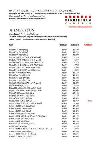
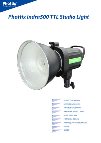
EnINSTRUCTION MANUALThank you for purchasing aPhottix productNote: Before using the Phottix Indra500 TTL Studio Light, please read this instruction manual carefully.The Phottix Indra500 TTL is a battery and AC powered portable studio light witha built-in radio and optical pulse wireless receiving function. It offers TTL, Manual and Multi Stroboscopic modes, as well as high speed sync and second curtainsync functions. The Phottix Indra500 TTL Studio Light is compatible with manyexisting Phottix products.Table of ContentParts and Functions . . 2Flash Modes . 8Wireless Receiving Modes . 9Custom Functions . 12Technical Specs . 13Safety instructions The Indra500 contains high voltage electronic parts. Do not disassemble or attempt to repair the Indra500. Keep this product out of the reachof children. Never use this product near combustible gases, solvents or in an environment with a high electrical charge.Make sure all plugs and cables are well connected during chargingand use. Disconnect the Indra500 TTL Studio light from a power source for 10minutes before changing the flash tube. Use caution, the flash tube canget very hot. Do not touch the external power port and ensure it does not have con-tact with any metal objects – this could cause electric shocks and seriousinjury. The external power source should not exceed the technical specifica-tions in this manual.The external power should be used in an environment with good ventilation. Do not use this product in dusty or sandy conditions.PartsFull View1. Front Cover2. Umbrella Holder3. Quick-ReleaseLocking Latch4. Handle5. 3.5mm Sync Port6. USB Output Port7. External Power Port8. Angle AdjustmentRatchet Handle9. Mounting Column10. Clamp Screw This product is not waterproof. Keep it away from rain, snow and highhumidity conditions. Do not clean the product with organic solvent or alcohol-based liquid. Do not put opaque objects in front of the studio flash head when firingthe studio light. The heat energy emitted by the Indra500 may cause objects to burn, or cause damage to the studio flash tube. Use your studio light safely. Do not fire the Indra500 into the eyes ofpeople or animals at short distances this may cause damage to the eyesand/or blindness.Do not leave the studio light in a hot location (direct sunlight, in aclosed car, etc.). Should you notice smoke or an unusual smell coming from this prod-uct, immediately turn off the power switch on the studio light.Turn off the power switch on the studio light when not being used foran extended period of time. Remove the front cover before operating the studio light. Otherwise,the front cover will get deformed or cause a fire due to the high temperature of the studio light. Use caution in touching the studio flash head after use. It may still behot and could cause burns. Consult local authorities on the proper disposal or recycling of a Phot-tix Indra500 TTL Studio Light.2Back View11. LCD Display12. Function Button 113. Function Button 214. Test/Ready Button15. Adjust/Set Knob16. Power Switch17. Modeling Light Switch18. Function Button 319. Function Button 420. Optical Signal SensorFront View21. Mounting Slot22. Glass Dome23. LED Modeling Light24. Flash Tube25. Reflector
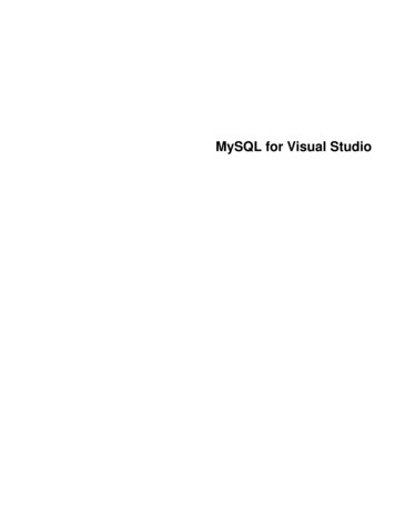
EnExternal Power PortThe Indra500 TTL Studio Light can be connected to the Phottix Indra AC Adapter or the Phottix Indra Battery Pack through the external power port.Please note:When connecting the external power source, only use Phottix flash powercords designed for use with the Indra500 TTL Studio Light.INSTRUCTION MANUAL3. Connect the AC Adapter to the mains supply.4. Turn on the main power switch and the output power switch on the AC Adapter.5. Turn on the power switch on the Phottix Indra500 TTL Studio Light.Disconnecting the Indra500 from the externalpower sourceDisconnecting the Phottix Indra Battery PackConnecting the Indra500 to the external powersourceUsing the Phottix Indra Battery Pack1. Turn off the power switch on the Indra500 TTL Studio Light.2. Move the output toggle switch on the battery pack to the “OFF” position.3. Unplug the flash power cord according to picture 4.1. Insert one end of the included flash power cord into the external power porton the Indra500 TTL Studio Light. (See picture 1)Note: To insert properly, please align the red dots on the cable and port.4. Unplug the other end according to picture 6.Disconnecting the Phottix Indra AC Adapter2. Insert the other end into the output port on the Phottix Indra Battery Pack.(See picture 2)3. Turn on the Output Toggle Switch on the Battery Pack.1. Turn off the power switch on the Indra500 TTL Studio Light.2. Turn off the main power switch and output power switch on the AC Adapter.Unplug the flash power cord according to picture 5.3. Unplug the flash power cable from the Phottix Indra Studio Light (picture 6).4. Turn on the power switch on the Phottix Indra500 TTL Studio Light.Using the Phottix Indra AC Adapter1. Insert one end of the included flash power cord into the external power porton the Indra500 TTL Studio Light. (See picture 1)Note: To insert properly, please align the red dots on the cable and port.2. Insert the other end into the output port on the Phottix Indra AC Adapter.(See picture 3)Attaching and removing the ReflectorTo attach the reflector1. Hold the Indra500 with one hand.2. Align the reflector with the mounting slot using your other hand.33. Insert and rotate the reflector clockwise following the direction of the arrowin the diagram until the lock engages with a click. This ensures the reflector is
INSTRUCTION MANUALEnlocked. (See picture7)2. The USB port is used for firmware upgrades. Firmware announcements andinstructions will be made available on Phottix websites.Please note:Only the manual mode is supported when a flash trigger is connected via thesync port.Transmission Channels4. If using an umbrella, make sure the umbrella pass-through hole in the reflector is aligned with the umbrella holder on the Indra studio light.To remove the reflector1. Push the quick-release locking latch with one hand.2. Rotate the reflector anti-clockwise in the same direction as the arrow in thediagram and remove it from the Indra500 with the other hand. (See picture 8)The Phottix Indra500 TTL Studio Light Wireless system has four channels; 1, 2,3, and 4. The same channel needs to be set on the Indra500 TTL Studio Lightwhen in wireless receiving mode as on the triggering device or flashes used totrigger the Indra.Quick Flash FunctionThe Quick Flash function allows the studio light to fire when it is not fully charged, i.e. the status LED is still flashing green. Quick Flash recycle times are faster;this helps for snap photography at short distances.Quick Flash can be used for continuous drive modes, Quick Flash for continuousshot function can be enabled or disabled in the Menu (See the Menu sectionbelow).Please note:Note: Please be aware to keep the reflector parallel to the mount of the studiolight while removing the reflector to prevent it touches the glass dome and incur damage.The Quick Flash Function makes flash firing a priority. Under-exposure couldresult if the subject is located too far from the camera.Flash Exposure Bracketing – FEBUsing the Umbrella HolderThe Phottix Indra500 TTL has an umbrella holder on the top of the light, makingit easy to mount umbrellas and umbrella-style softboxes. Using the umbrellamount is simple: Insert the umbrella shaft into the umbrella holder on the Phottix Indra Studio Light. Turn the screw on the umbrella holder to tighten againstthe umbrella shaft.Using the Softbox MountThe Phottix Indra500 TTL features a Bowen’s-compatible locking ring for softboxes, and other light modifying accessories. Using the Softbox Mount is thesame as mounting and removing the Phottix Indra Reflector (above).To attach: Align the softbox speed ring with the mounting slot on the Indra500.Insert and rotate the softbox mount clockwise following the direction of thearrow in the diagram until the lock engages with a click. (See picture7)To remove: Push the quick-release locking latch backwards, and rotate the softbox mount anti-clockwise to remove it from the Indra500. (See picture 8)Sync and USB Ports1. A Phottix flash trigger (Phottix Odin TTL, Strato II Multi and Strato TTL) or camera can be connected to the Indra’s 3.5mm sync port using a compatible cable.The device will then be able to trigger the Indra500 TTL Studio Light.4Flash Exposure Bracketing (FEB) can be used to automatically change the flashpower over a series of photos. The camera will record a series of images with different exposures. FEB is useful in run-and-gun situations as well as when shooting scenes with different lighting conditions to help ensure a properly exposedphoto. FEB can also be used for HDR photography.The FEB function is supported but cannot be set on the Indra500 TTL StudioLight. The availability of this function depends on whether the trigger or camerais equipped with an FEB function. See your camera manual for more informationon Flash Exposure Bracketing.Flash Exposure Lock – FEL/FV LockFlash Exposure Lock (FEL, also FV Lock in Nikon camera) can be used to lock theflash exposure before a photo is taken. This is useful when manual spot metering is being used in a scene with different lighting conditions. While in TTLmode, press the camera’s function button to use this function. See your camerauser manual for more information on FEL functions and usage.The FEL function is supported but cannot be set on the Indra500 TTL StudioLight. The availability of this function depends on whether the trigger or camerais equipped with an FEL function. See you camera manual for more informationon Flash Exposure Lock.
EnHigh Speed Sync – HSS/Auto FPHigh Speed Sync (HSS) mode is used to shoot at shutter speeds higher than acamera’s set flash sync speed (typically 1/200-1/250s). This is useful when usingaperture priority mode and in limiting ambient light. HSS results may vary withdifferent camera models – refer to your camera user manual for more details.Please note:1. HSS function is supported by the Phottix Indra500 TTL Studio Light, but itcannot be set on the studio light itself.2. The camera, flash trigger and receiving mode can greatly affect HSS mode.For best results in HSS mode please use recommended Phottix flash triggers.Please see the “Compatibility Table” below and refer to your flash trigger andcamera user manuals for more details.3. HSS function will not work in Manual and Multi Stroboscopic mode.4. Use the HSS mode frequently will shorten the flash tube life.5. Nikon’s flash protocols may limit the maximum sync speed of some Nikoncamera bodies.Compatibility TableSecond Curtain Sync - SCSThe Phottix Indra500 TTL Second Curtain Sync function makes the studio lightfire at the end of an exposure, not the beginning. This helps capture special effects when using slow shutter speeds.Please note:1. SCS function is supported by the Phottix Indra500 TTL Studio Light, but itcannot be set on the studio light itself. Instead please set the SCS function onyour camera or flash trigger. For more details, please refer to your flash triggerand camera user manuals.2. SCS function will not work in Multi Stroboscopic mode.Test/Ready Button1. Pressing the test button will trigger the studio light. This can be used for metering in Manual mode.2. This button also offers a Flash-ready indication function. The LED indicator on5INSTRUCTION MANUALthe button will flash green when the light has the minimum recycle charge. Itwill flash red when fully charged.
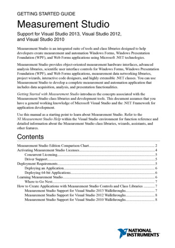
EnMenu6INSTRUCTION MANUAL
EnINSTRUCTION MANUALMenu SettingsUse the four function buttons below the LCD display to select the corresponding function setting options. You can edit each setting when the selected function is highlighted. Depending on the LCD color screen settings this will be ineither: red, white, or yellow (The LCD color screen setting and the LCD displaysensor setting will be shown in the Menu list).1. Turn the “Adjust/Set knob” to change the setting.2. When finished press the corresponding function button, or the “Adjust/Setknob” to confirm and exit.The LCD DisplayWireless receiving modes:Odin-C,Odin-N,Strato II,Opt-SlaveRX OFFFlash modes:TTL, M, MultiQuick flash: Enable: DisableBeep signalONOFFFlash exposurecompensation/Flash outputWireless receiving channelMenu: see moredetails in Menufunction partWirelessreceiving groupMenu Screen7Modeling light: Manual01-09 levels, OFF
INSTRUCTION MANUALEnAuto-Save Functions3. Turn the “Adjust/Set knob” to change the modeling light mode from Manual (01-09 stop) or OFF.The Indra500 TTL will remember studio light settings. Previous settings will beretained each time it is turned on.4. Press “Adjust/Set knob” to confirm the settings and exit the editing mode.Flash ModesModeling Flash1. Pressing the camera depth-of-field preview button (if available) will fire thestudio light continuously for 1 second. The modeling flash allows you to see thelighting effects and balance on the subject. (Please see your camera manual formore information on the DOF button and button assignment.)2. The modeling flash is available in all modes, TTL, Manual and Multi.The Phottix Indra500 TTL Studio Light has three flash modes: TTL Auto, Manualand Multi.TTL Flash ModeWhen the Phottix Indra500 TTL Studio Light is set to TTL mode, the studio lightwill fire at the selected flash mode and flash power, as set on a Phottix Odin orother Phottix compatible flash trigger featuring power control.Modeling LightThe Phottix Indra500 TTL is equipped with an LED modeling light. This is helpful for both previewing lighting set-ups and assisting with focusing in dimly litenvironments.Flash Exposure Compensation-FECThe Modeling Light has two modesThe Phottix Indra500 TTL Studio Light can be used to adjust Flash ExposureCompensation (FEC) from-3 to 3 in 1/3rd stops. This is useful in environmentswhere fine-tuning of the TTL system is needed.1. Manual mode: 9 brightness levels from 01 to 09 are available.Please note:2. OFF mode: The modeling light will be turned off.Please note:1. When the studio light is firing, the modeling light will not turn off automatically.2. Using the modeling light uses a lot of battery power.Adjusting the brightness of the Modeling LightThe modeling light can be turned on/off via menu optionor with the modeling light swtichin.Via Menu option1. Press Function Button 4 untilappears on the LCD display.2. Press the corresponding function button to3. When the modeling light optionthe LCD display.is selected, it will be highlighted on4. Turn the “Adjust/Set knob” to change the modeling light mode from Manual (01-09 stop) or OFF.5. Press the function button corresponding toor the “Adjust/Setknob” to confirm the settings and exit the editing mode.Via Modeling Light SwitchManual Flash ModeIn Manual mode the studio light will fire at the power levels set. The PhottixIndra500 TTL Studio Light can be adjusted from 1/128 to 1/1 in 1/3 stop increments (1/128, 1/64, 1/32, 1/16, 1/8, 1/4, 1/2, and 1/1). Flash modes and powerof the studio light cannot be adjusted and controlled on the triggering device.With Multi Stroboscopic mode a series of rapid flashes will be fired. The flashcount, frequency and power of these flashes can be programmed on the PhottixIndra500 TTL Studio Light. Multi mode is useful for capturing multiple images ofa moving subject in the same photo and for other special effects.In Multi Stroboscopic mode, the studio light will be fired at the programmedmanual flash power, flash counts (1-100), and frequency (1-100Hz). The flashpower can be set from 1/128 to 1/4 in 1/1 stop increments (1/128, 1/64, 1/32,1/16, 1/8, and 1/4). Flash modes and power of the studio light cannot be adjusted and controlled on the triggering device.Please note:1. Press the modeling light switch to turn on/off the modeling light.82. If the triggering device is set to Manual mode (if available) and the studiolight is set to TTL mode with Flash Exposure Compensation Value, then theFlash EV Value will be used to calculate the final flash output.Multi Stroboscopic Flash Mode.2. When the modeling light is turned on the modeling light iconhighlighted on the LCD display.1. If both the triggering device (if TTL mode is available) and the studio lightare set to TTL modes and EV adjustment is set on both units, then the final exposure value will be the sum of the two Flash Exposure Compensation Values.will be1. Overheating and even damage to the flash tube can be resulted from excessive use of the Multi Stroboscopic mode.2. If overheated the flash will automatically increase charging time. If the temperature continues to rise, the light will stop firing.
INSTRUCTION MANUALEnWireless Receiving ModeStrato II Radio Frequency Receiving ModeThe Phottix Indra500 TTL Studio Light is equipped with 5 wireless receivingmodes: Odin-C, Odin-N, Strato II, Opt-Slave and RX OFF. Please see below formore details.Supported Flash ModesThis mode allows the Indra500 TTL Studio Light to be triggered by the PhottixOdin TTL Flash Trigger TCUs for Canon/Nikon, the Phottix Mitros TTL Transceiver Flash for Canon/Nikon in Odin Tx mode, the Phottix Strato TTL transmitterfor Canon/Nikon or by the Phottix Strato II Multi transmitter for Canon/Nikon.To work correctly they must be set to the same channel and in the same group.Please note:HSS, SCS, and TTL are not supported in Strato II Radio Frequency Receiving Mode.How to use:1. Press Function Button 4 or turn the “Adjust/Set Knob” untilpears on the LCD display.ap-2. Press the corresponding function button to. The wireless receving function option will be highlighted on the LCD display.3. Turn the “Adjust/Set Knob” to change the wireless mode to Strato II.4. Press the “Adjust/Set Knob” to confirm the setting.Odin-C Radio Frequency Receiving ModeThis mode allows the Indra500 TTL Studio Light to be triggered by a PhottixOdin TTL Flash Trigger TCUs for Canon or by a Phottix Mitros TTL TransceiverFlash for Canon in Odin TX mode. To work correctly they must be set to the samechannel and in the same group.How to use:1. Press Function Button 4 or turn the “Adjust/Set Knob” untilpears on the LCD display.ap-2. Press the corresponding function button to. The wireless receving function option will be highlighted on the LCD display.3. Turn the “Adjust/Set Knob” to change the wireless mode to Odin-C.4. Press the “Adjust/Set Knob” to confirm the setting.5. Press the corresponding function button tofrom TTL, Manual or Multi.to adjustto adjustOpt-Slave Optical Pulse Receiving ModeIn this mode any other studio lights or flashes fired nearby will trigger the Indra500 TTL Studio Light.Please note:Pre-flashes from nearby TTL flashes will trigger the Phottix Indra if set in OptSlave mode. Please take care when using this mode that nearby TTL flashesdo not trigger the Phottix Indra before you are ready.1. Press Function Button 4 or turn the “Adjust/Set Knob” untilpears on the LCD display.ap-2. Press the corresponding function button to. The wireless receving function option will be highlighted on the LCD display.This mode allows the Indra500 TTL Studio Light to be triggered by a PhottixOdin TTL Flash Trigger TCUs for Nikon or by a Phottix Mitros TTL TransceiverFlash for Nikon in ODIN TX mode. To work correctly they must be set to the samechannel and in the same group.3. Turn the “Adjust/Set Knob” to change the wireless mode to Opt-Slave.4. Press the “Adjust/Set Knob” to confirm the setting.RX OFF ModeHow to use:1. Press Function Button 4 or turn the “Adjust/Set Knob” untilpears on the LCD display.ap-2. Press the corresponding function button to. The wireless receving function option will be highlighted on the LCD display.3. Turn the “Adjust/Set Knob” to change the wireless mode to Odin-N.4. Press the “Adjust/Set Knob” to confirm the setting.into adjustIn this mode wireless receiving is turned off.How to use:1. Press Function Button 4 or turn the “Adjust/Set Knob” untilpears on the LCD display.ap-2. Press the corresponding function button to. The wireless receving function option will be highlighted on the LCD display.3. Turn the “Adjust/Set Knob” to change the wireless mode to RX OFF.4. Press the “Adjust/Set Knob” to confirm the setting.9inHow to use:inOdin-N Radio Frequency Receiving Mode5. Press the corresponding function button tofrom TTL, Manual or Multi.5. Press the corresponding function button tofrom Manual and Multi.
En5. Press the corresponding function button tofrom Manual and Multi.into adjustINSTRUCTION MANUALside-down and Auto by sensor).7. Press the corresponding function button toin. the continuous flash mode option will be highlighted on the LCD screen. Turn the “Adjust/Set knob” to turn the Quick Continuous flash mode on/off.For Odin-C/Odin-N/Strato II8. Press the corresponding function button toFunctions in Multi modein. Turn the“Adjust/Set knob”to turn the sound on/off.1. Press the corresponding function button toin. Turn the“Adjust/Set knob”to adjust the flash power from 1/4 to 1/128 - 6 stops.2. Press the corresponding function button toin“Adjust/Set knob” to adjust the Modeling Light mode (OFF/01-09). Turn the3. Press the corresponding function button to“Adjust/Set knob”to adjust the Chanel from 1-4.in. Turn the4. Press the corresponding function button to“Adjust/Set knob” to adjust the Group from A, B to C.in. Turn theFunctions in Manual modein. Turn the5. Press the corresponding function button to“Adjust/Set knob”to adjust the LCD Color Screen Setting (Classic, Dynamic, Elegant).in. Turn the6. Press the corresponding function button to“Adjust/Set knob” to adjust the flash count from 1-100 times (based on the flashfrequency and flash output).1. Press the corresponding function button toin. Turn the“Adjust/Set knob” to adjust the flash power from 1/1 to 1/128 in 1/3rd stop increments.2. Press the corresponding function button toin“Adjust/Set knob” to adjust the Modeling Light mode (OFF/01-09). Turn the3. Press the corresponding function button to“Adjust/Set knob” to adjust the Chanel from 1-4.in. Turn the4. Press the corresponding function button to“Adjust/Set knob”to adjust the Group from A, B to C.in. Turn the. Turn thein. Turn the5. Press the corresponding function button to“Adjust/Set knob”to adjust the LCD Color Screen Setting (Classic, Dynamic, Elegant).8. Press the corresponding function button toin. Turnthe “Adjust/Set knob”to adjust the LCD Display Sensor Setting (Regular, Upside-down and Auto by sensor).6. Press the corresponding function button toin. Turnthe “Adjust/Set knob” to adjust the LCD Display Sensor Setting (Regular, Upside-down and Auto by sensor).in, the Contin9. Press the corresponding function button touous flash mode option will be highlighted on the LCD screen. Turn the “Adjust/Set knob” to turn the Quick Continuous flash mode on/off.in. the7. Press the corresponding function button toContinuous flash mode option will be highlighted on the LCD screen. Turn the“Adjust/Set Knob” to turn the Quick Continuous flash mode on/off.in7. Press the corresponding function button to“Adjust/Set knob”to adjust the flash frequency from 1-100Hz.10. Press the corresponding function button to“Adjust/Set knob”to turn the sound on/off.in. Turn theFor Odin-C/Odin-N8. Press the corresponding function button to“Adjust/Set knob”to turn the sound on/off.in. Turn theFor Opt-Slave/RX OFFFunctions in TTL modeFunctions in Manual mode1. Press the corresponding function button toin. Turn the“Adjust/Set knob”to adjust the Flash Exposure Compensation Value from -3.0EVto 3.0EV.1. Press the corresponding function button toin. Turnthe “Adjust/Set knob”to adjust the flash power from 1/1 to 1/128 in 1/3rd stopincrements.2. Press the corresponding function button toin“Adjust/Set knob”to adjust the Modeling Light mode (OFF/01-09). Turn the2. Press the corresponding function button toin“Adjust/Set knob” to adjust the Modeling Light mode (OFF/01-09).3. Press the corresponding function button to“Adjust/Set knob”to adjust the Chanel from 1-4.in. Turn the4. Press the corresponding function button to“Adjust/Set knob”to adjust the Group from A, B to C.in. Turn thein. Turn the3. Press the corresponding function button to“Adjust/Set knob”to adjust the LCD Color Screen Setting (Classic, Dynamic, Elegant).in. Turn the5. Press the corresponding function button to“Adjust/Set knob”to adjust the LCD Color Screen Setting (Classic, Dynamic, Elegant).6. Press the corresponding function button toin. Turnthe “Adjust/Set knob”to adjust the LCD Display Sensor Setting (Regular, Up10For Odin-C/Odin-N/Strato II. Turn the4. Press the corresponding function button toin. Turnthe “Adjust/Set knob”to adjust the LCD Display Sensor Setting (Regular, Upside-down and Auto by sensor).in, the Contin5. Press the corresponding function button touous flash mode option will be highlighted on the LCD screen. Turn the “Adjust/Set knob” to turn the Quick Continuous flash mode on/off.
En6. Press the corresponding function button to“Adjust/Set knob”to turn the sound on/off.in. Turn theFor RX OFFFunctions in Multi mode1. Press the corresponding function button toin. Turn the“Adjust/Set knob” to adjust the flash power from 1/4 to 1/128 - 6 stops.2. Press the corresponding function button toin“Adjust/Set knob” to adjust the Modeling Light mode (OFF/01-09). Turn thein. Turn the3. Press the corresponding function button to“Adjust/Set knob”to adjust the LCD color screen setting (Classic, Dynamic, Elegant).into adjust4. Press the corresponding function button tothe flash count from 1-100 times (based on the flash frequency and flash output).in5. Press the corresponding function button to“Adjust/Set knob”to adjust the flash frequency from 1-100Hz. Turn the6. Press the corresponding function button toin. Turnthe “Adjust/Set knob”to adjust the LCD Display Sensor Setting (Regular, Upside-down and Auto by sensor).in, the Con7. Press the corresponding function button totinuous flash mode option will be highlighted on the LCD screen. Turn the “Adjust/Set Knob” to turn the Quick Continuous flash mode on/off.8. Press the corresponding function button to“Adjust/Set knob”to turn the sound on/off.in. Turn theRemarks:If the “Adjust/Set knob” or the corresponding function button is not pressedto confirm the selected parameter, the selected parameter will be confirmedby default within 10 seconds.11INSTRUCTION MANUAL
EnINSTRUCTION MANUALCustom FunctionsThe Phottix Indra500 TTL Studio Light comes with a number of programmablecustom functions. To edit these functions (see below):2. Press Function button 1 or Function button 2 to cycle through the menuitems – C.Fn 00 to 03.1. Press and hold Function button 4 and the “Adjust/Set knob” for 3 seconds toenter the C.Fn Menu Screen.3. Turn the “Adjust/Set knob” to change the functions within the menu.4. Press Function button 4 to exit the C.Fn menu.Custom Functions ChartReplacing the flash tube1. Disconnect the Indra500 TTL Studio light from a power source for 10 minutesbefore changing the flash tube.5. Insert a new flash tube into the snap slot. (Picture 11)2. Remove the Reflector as shown above.3. Gently separate the Glass Dome from the snap mount, remove the GlassDome. (Picture 9)6. Mount the Glass Dome align the snap mount. (Picture 12)4. Gently hold the flash tube to remove it from the snap slot. (Picture 10)7. Attach the Reflector as shown above.12Note: Please wear gloves instead of touching the flash tube directly when replacing the flash tube.
EnResetting to Factory DefaultsINSTRUCTION MANUALTechnical SpecificationThe Indra500 TTL Studio Light can be reset to factory defaults.Max power: 500WsPress and hold both Function button 1 and the “Adjust/Set knob” for 3 seconds.This will reset all function settings to factory defaults.Adjustable power stops: 8 Stops (4-500Ws)Power adjustment: In 1/3stop or full stop incrementFlash modes: TTL Auto, Manual (M), MultiChecking the Studio Light InformationPressing the combination keys can check the Phottix Indra500 TTL Studio Lightinformation: Hardware, software, icon library, and product serial number.1. Press and hold Function button 2 and “Adjust/Set Knob” for 3 seconds. Theinformation display screen will show the hardware, software, icon library, andproduct serial number.2. Press any button to exit the information display screen and return back to thestandard screen.3. Triggering the studio light or camera focusing, or taking photos when the studio light is displaying the version information will cause the studio light to exitthe version display screen and return back to the standard screen.Changes to the Studio Light CapacitorIf the Indra500 is not used for some time physical changes will take place withinthe flash’s capacitor. Make sure to turn on the flash for a minimum of 10 minutesevery three months to prevent any changes.Light angle: 60 Guide Number: 45/147.6 (ISO100, m/ft)Color temperature: 5600 200K (Color temperature may vary at low powersettings)Flash duration time: t 11/250s - 1/12000sStroboscopic flash: Frequency: 1-100Hz, Flash Count: 1-100 timesHSS&SCS: Support*Recycling time(at 1/1 flash power levels; the indicator will light red)Phottix Indra AC Adapter: Single/Two flashes: 0.9s/1.7sPhottix Indra Battery Pack (10AH): H mode Single/Two flashes: 1s/2.3sS mode Single/Two flashes: 1.4s/5.4sPhottix
The Phottix Indra500 TTL is a battery and AC powered portable studio light with a built-in radio and optical pulse wireless receiving function. It offers TTL, Manu-al and Multi Stroboscopic modes, as well as high speed sync and second curtain sync functions. The Phottix Indra500 TTL Studio