Transcription
r Manual
Important User InformationSolid state equipment has operational characteristics differing from those ofelectromechanical equipment. Safety Guidelines for the Application, Installation andMaintenance of Solid State Controls (publication SGI-1.1 available from your localRockwell Automation sales office or online athttp://literature.rockwellautomation.com) describes some important differencesbetween solid state equipment and hard-wired electromechanical devices. Because ofthis difference, and also because of the wide variety of uses for solid state equipment,all persons responsible for applying this equipment must satisfy themselves that eachintended application of this equipment is acceptable.In no event will Rockwell Automation, Inc. be responsible or liable for indirect orconsequential damages resulting from the use or application of this equipment.The examples and diagrams in this manual are included solely for illustrative purposes.Because of the many variables and requirements associated with any particularinstallation, Rockwell Automation, Inc. cannot assume responsibility or liability foractual use based on the examples and diagrams.No patent liability is assumed by Rockwell Automation, Inc. with respect to use ofinformation, circuits, equipment, or software described in this manual.Reproduction of the contents of this manual, in whole or in part, without writtenpermission of Rockwell Automation, Inc., is prohibited.Throughout this manual, when necessary, we use notes to make you aware of tifies information about practices or circumstances that can causean explosion in a hazardous environment, which may lead to personalinjury or death, property damage, or economic loss.Identifies information that is critical for successful application andunderstanding of the product.Identifies information about practices or circumstances that can leadto personal injury or death, property damage, or economic loss.Attentions help you identify a hazard, avoid a hazard, and recognizethe consequenceSHOCK HAZARDLabels may be located on or inside the equipment, for example, a driveor motor, to alert people that dangerous voltage may be present.BURN HAZARDLabels may be located on or inside the equipment, for example, a driveor motor, to alert people that surfaces may be dangeroustemperatures.The first line of trademarks is an example; the brand or product name changes according to publication but the rest of the line should remain thesame. The second line should be used exactly as listed below in any case where it applies.Allen-Bradley, ControlLogix, and RSLinx are trademarks of Rockwell Automation, Inc.Trademarks not belonging to Rockwell Automation are property of their respective companies.
Table of ContentsImportant User Information . . . . . . . . . . . . . . . . . . . . . . . . . . . . . . . . 1-2PrefacePurpose of This Manual. . . . . . . . . . . . . . . . . . . . . . . . . . . . . . . Preface-iWho Should Use This Manual. . . . . . . . . . . . . . . . . . . . . . . . . . Preface-iOther Resources. . . . . . . . . . . . . . . . . . . . . . . . . . . . . . . . . . . . . Preface-iChapter 11756-DH485 Module OverviewIntroduction . . . . . . . . . . . . . . . . . . . . . . . . . . . . . . . . . . . . . . . . . . . . .What the Module Does . . . . . . . . . . . . . . . . . . . . . . . . . . . . . . . . . . . .Module Requirements . . . . . . . . . . . . . . . . . . . . . . . . . . . . . . . . . . . . .Module Features. . . . . . . . . . . . . . . . . . . . . . . . . . . . . . . . . . . . . . . . . .Prevent Electrostatic Discharge . . . . . . . . . . . . . . . . . . . . . . . . . . . . .Removal and Insertion Under Power . . . . . . . . . . . . . . . . . . . . . . . . .Typical Applications. . . . . . . . . . . . . . . . . . . . . . . . . . . . . . . . . . . . . . .Remote Messaging . . . . . . . . . . . . . . . . . . . . . . . . . . . . . . . . . . . . . . . .Remote Upload and Download . . . . . . . . . . . . . . . . . . . . . . . . . .Routing Limitations . . . . . . . . . . . . . . . . . . . . . . . . . . . . . . . . . . . . . . .DH-485 and CIP Messaging . . . . . . . . . . . . . . . . . . . . . . . . . . . . .Alphanumeric Indicators . . . . . . . . . . . . . . . . . . . . . . . . . . . . . . . .1-11-11-11-21-31-41-51-71-71-81-81-9Chapter 2Overview of the DH-485 NetworkiIntroduction . . . . . . . . . . . . . . . . . . . . . . . . . . . . . . . . . . . . . . . . . . . . . 2-1DH-485 Network Description . . . . . . . . . . . . . . . . . . . . . . . . . . . . . . 2-1DH-485 Network Protocol . . . . . . . . . . . . . . . . . . . . . . . . . . . . . . . . . 2-2DH-485 Token Rotation . . . . . . . . . . . . . . . . . . . . . . . . . . . . . . . . . . . 2-2DH-485 Network Initialization . . . . . . . . . . . . . . . . . . . . . . . . . . . . . . 2-2Devices that Use the DH-485 Network . . . . . . . . . . . . . . . . . . . . . . . 2-31747-AIC Isolated Link Coupler for DH-485 . . . . . . . . . . . . . . . . . . 2-41761-NET-AIC Advanced Interface Converter Product Overview . 2-6Operating Modes . . . . . . . . . . . . . . . . . . . . . . . . . . . . . . . . . . . . . . . . . 2-6Device Compatibility . . . . . . . . . . . . . . . . . . . . . . . . . . . . . . . . . . . . . . 2-6Node Address Identification . . . . . . . . . . . . . . . . . . . . . . . . . . . . 2-7Misconception about the 1761-NET-AIC Converter . . . . . . . . . . . . 2-71747-UIC USB to DH-485 Interface Converter . . . . . . . . . . . . . . . . 2-7Example System Configuration . . . . . . . . . . . . . . . . . . . . . . . . . . . . . . 2-8Configure the SLC 5/03, SLC 5/04, and SLC 5/05 ControllerChannel 0 for DH-485. . . . . . . . . . . . . . . . . . . . . . . . . . . . . . . . . . 2-9Important Planning Considerations . . . . . . . . . . . . . . . . . . . . . . . . . 2-10Hardware Considerations . . . . . . . . . . . . . . . . . . . . . . . . . . . . . . 2-10Software Considerations . . . . . . . . . . . . . . . . . . . . . . . . . . . . . . . 2-12Additional Resources . . . . . . . . . . . . . . . . . . . . . . . . . . . . . . . . . . . . . 2-13Publication 1756-UM532A-EN-P - May 2006
Table of ContentsiiChapter 3Use Data Highway 485 NetworkIntroduction . . . . . . . . . . . . . . . . . . . . . . . . . . . . . . . . . . . . . . . . . . . . . 3-1What Is Data Highway 485? . . . . . . . . . . . . . . . . . . . . . . . . . . . . . . . . 3-1Link Design . . . . . . . . . . . . . . . . . . . . . . . . . . . . . . . . . . . . . . . . . . 3-2Two Methods of Communication Over a DH-485 Network . . . . . . 3-2Use DH-485 Messaging . . . . . . . . . . . . . . . . . . . . . . . . . . . . . . . . . . . . 3-3Local DH-485 Messaging . . . . . . . . . . . . . . . . . . . . . . . . . . . . . . . 3-3Limitations of Local DH-485 Messaging . . . . . . . . . . . . . . . . . . . 3-5Remote DH-485 Messaging . . . . . . . . . . . . . . . . . . . . . . . . . . . . . 3-5Configuration Information in DH-485 Messaging. . . . . . . . . . . . . . 3-11Application Timeout . . . . . . . . . . . . . . . . . . . . . . . . . . . . . . . . . . . . . 3-12Example DH-485 Network Routing Configuration. . . . . . . . . . . . . 3-13Use the Common Industrial Protocol (CIP) Messaging. . . . . . . . . . 3-14Chapter 4Use RSLinx Software to Create aRouting TableIntroduction . . . . . . . . . . . . . . . . . . . . . . . . . . . . . . . . . . . . . . . . . . . . .Choose the Correct Software. . . . . . . . . . . . . . . . . . . . . . . . . . . . . . . .Use RSLinx Software to Create a Routing Table . . . . . . . . . . . . . . . .What Is a Routing Table? . . . . . . . . . . . . . . . . . . . . . . . . . . . . . . .ControlLogix Routing . . . . . . . . . . . . . . . . . . . . . . . . . . . . . . . . . .Create the Routing Table . . . . . . . . . . . . . . . . . . . . . . . . . . . . . . . . . . .Set the Controller Slot . . . . . . . . . . . . . . . . . . . . . . . . . . . . . . . . . .4-14-14-24-24-24-34-8Chapter 5Communicate from an SLC 5/03Controller to a Logix Controllerover a DH-485 NetworkPublication 1756-UM532A-EN-P - May 2006Introduction . . . . . . . . . . . . . . . . . . . . . . . . . . . . . . . . . . . . . . . . . . . . .Hardware Configuration . . . . . . . . . . . . . . . . . . . . . . . . . . . . . . . . . . .Use the Controller Slot to Route the Local Message . . . . . . . . . . . . .Create a Local Message in RSLogix 500 . . . . . . . . . . . . . . . . . . . . . . .Configure the Message. . . . . . . . . . . . . . . . . . . . . . . . . . . . . . . . . . . . .Create a Logic Map for the Local Message inRSLogix 5000 Software . . . . . . . . . . . . . . . . . . . . . . . . . . . . . . . . .5-15-25-35-45-55-6
Table of ContentsiiiChapter 6Communicate Between SLCControllers over DH and DH485NetworksIntroduction . . . . . . . . . . . . . . . . . . . . . . . . . . . . . . . . . . . . . . . . . . . . . 6-1SLC 5/04 Controller Sends a Remote Message . . . . . . . . . . . . . . . . . 6-2Hardware Configuration . . . . . . . . . . . . . . . . . . . . . . . . . . . . . . . . 6-2Create the Routing Table in RSLinx Software . . . . . . . . . . . . . . . 6-3Configure the SLC 5/03 Controller Channel 1 Link ID . . . . . . . 6-4Configure the SLC 5/04 Channel 1 Link ID . . . . . . . . . . . . . . . . 6-5Create a Message in RSLogix 500 . . . . . . . . . . . . . . . . . . . . . . . . . 6-6Configure the Message . . . . . . . . . . . . . . . . . . . . . . . . . . . . . . . . . 6-7SLC 5/03 Controller Sends a Remote Message . . . . . . . . . . . . . . . . . 6-8Hardware Configuration . . . . . . . . . . . . . . . . . . . . . . . . . . . . . . . . 6-8Create the Routing Table in RSLinx Software . . . . . . . . . . . . . . . 6-9Create a Remote Message in RSLogix 500 . . . . . . . . . . . . . . . . . 6-10Configure the Message . . . . . . . . . . . . . . . . . . . . . . . . . . . . . . . . 6-11Chapter 7Communicate Between a PLC-5Controller and a Remote SLC 5/03Controller over Multiple DH-485NetworksIntroduction . . . . . . . . . . . . . . . . . . . . . . . . . . . . . . . . . . . . . . . . . . . . .Hardware Configuration . . . . . . . . . . . . . . . . . . . . . . . . . . . . . . . . . . .Create the Routing Table . . . . . . . . . . . . . . . . . . . . . . . . . . . . . . . . . . .Configure the PLC-5 DH Channel 1A Link ID . . . . . . . . . . . .Create a Message in RSLogix 5 . . . . . . . . . . . . . . . . . . . . . . . . . . . . . .Configure the Message. . . . . . . . . . . . . . . . . . . . . . . . . . . . . . . . . . . . .7-17-27-37-47-47-5Chapter 8Communicate from an SLC 5/05Controller to an SLC 5/03Controller over an EtherNet/IPNetworkIntroduction . . . . . . . . . . . . . . . . . . . . . . . . . . . . . . . . . . . . . . . . . . . . .Hardware Configuration . . . . . . . . . . . . . . . . . . . . . . . . . . . . . . . . . . .Create a Message in RSLogix 500 . . . . . . . . . . . . . . . . . . . . . . . . . . . .Configure the Message. . . . . . . . . . . . . . . . . . . . . . . . . . . . . . . . . . . . .Review the Multihop Feature in RSLogix 500 . . . . . . . . . . . . . . . . . .8-18-28-38-48-5Chapter 9Communicate to a SLC 5/03Controller on a DH-485 NetworkIntroduction . . . . . . . . . . . . . . . . . . . . . . . . . . . . . . . . . . . . . . . . . . . . .Hardware Configuration . . . . . . . . . . . . . . . . . . . . . . . . . . . . . . . . . . .Create a Message in RSLogix 5000 . . . . . . . . . . . . . . . . . . . . . . . . . . .Configure the Message. . . . . . . . . . . . . . . . . . . . . . . . . . . . . . . . . . . . .9-19-29-39-4Publication 1756-UM532A-EN-P - May 2006
Table of ContentsivChapter 10Communicate from a LogixController to an SLC 5/03Controller over EtherNet/IP andDH-485 NetworksIntroduction . . . . . . . . . . . . . . . . . . . . . . . . . . . . . . . . . . . . . . . . . . . .Hardware Configuration . . . . . . . . . . . . . . . . . . . . . . . . . . . . . . . . . .Create a Remote 1756-ENBT Message in RSLogix 5000 . . . . . . . .Configure the Message. . . . . . . . . . . . . . . . . . . . . . . . . . . . . . . . . . . .10-110-210-310-4Appendix ASpecificationsAppendix BTroubleshoot the 1756-DH485ModuleIntroduction . . . . . . . . . . . . . . . . . . . . . . . . . . . . . . . . . . . . . . . . . . . . . B-1Check Power Supply and Module Status . . . . . . . . . . . . . . . . . . . . . . B-1Interpret the LED Status Indicators . . . . . . . . . . . . . . . . . . . . . . . . . . B-2Interpret the Alphanumeric Indicators . . . . . . . . . . . . . . . . . . . . . . . . B-3Interpret the OKStatus Indicator. . . . . . . . . . . . . . . . . . . . . . . . . . . . . . . . . . . . . . . . . . . B-4Routing Errors in DH-485 Messaging . . . . . . . . . . . . . . . . . . . . . . . . B-4Routing Errors in Local DH-485 Messaging . . . . . . . . . . . . . . . . B-4Routing Errors in Remote DH-485 Messaging . . . . . . . . . . . . . . B-5IndexRockwell Automation Support . . . . . . . . . . . . . . . . . . . . . . . . BackcoverInstallation Assistance . . . . . . . . . . . . . . . . . . . . . . . . . . . . BackcoverNew Product Satisfaction Return . . . . . . . . . . . . . . . . . . . BackcoverPublication 1756-UM532A-EN-P - May 2006
PrefacePurpose of This ManualThis manual describes how to understand, configure, and troubleshoot yourControlLogix Data Highway 485 communication interface module.This manual also provides step-by-step procedures on how to use the1756-DH485 module to send DH-485 messages between ControlLogix, PLC,and SLC controllers in DH-485 applications.Who Should Use ThisManualUse this manual if you program applications that use 1756-DH485 modules.We assume you have a good understanding of the Data Highway 485 protocol.This user manual contains a brief description of the Data Highway 485network in Chapter 2, Overview of the DH-485 Network.Other ResourcesRefer to the manuals listed in the table Devices that Use the DH-485 Networkon page 2-3.iPublication 1756-UM532A-EN-P - May 2006
PrefaceiiNotes:Publication 1756-UM532A-EN-P - May 2006
Chapter11756-DH485 Module OverviewIntroductionWhat the Module DoesThis chapter describes the 1756-DH485 module, and what you must know anddo before you begin to use it.ForSeeWhat the Module Does1-1Module Requirements1-1Module Features1-2Prevent Electrostatic Discharge1-3Removal and Insertion Under Power1-4Typical Applications1-5Remote Messaging1-7Routing Limitations1-8The 1756-DH485 module supports the following types of communication: Data Highway 485 (DH-485) Messaging Connectivity to two separate DH-485 networks in one module Common Industrial Protocol (CIP) MessagingModule RequirementsThe following are required for using the 1756-DH485 communicationmodule: 1RSLinx Software, version 2.41 or laterNode address within the range of 0-31AIC link coupler (1761-NET-AIC) communications adapterCompatible with SLC 5/03 controllers or laterPublication 1756-UM532A-EN-P - May 2006
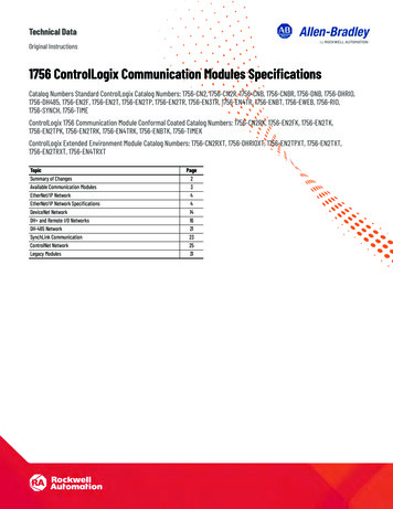
1-21756-DH485 Module OverviewModule FeaturesThe 1756-DH-485 module offers the following features: Sends messages between devices on DH-485 networks and devices onother networks such as ControlNet, EtherNet/IP, or other DH-485networks Bridges support to other NetLinx networks via the CLX gateway Configure channels and ports using RSLinx Classic software, version2.43 or later Accesses other networks by using a routing table editor that letsDH-485 devices use the 1756-DH485 module and ControlLogix chassis Supports all benefits and attributes of a ControlLogix communicationmodule Supports firmware upgradesTIPDownload firmware upgrades via the backplane. Donot use DH485 network for downloads. Removal and insertion under power (RIUP), can be removed andinserted under power without disrupting power to other modules in thechassisWARNING! When you insert or remove the module while backplanepower is on, an electrical arc can occur. This could cause anexplosion in hazardous location installations.Be sure that power is removed or the area is nonhazardousbefore proceeding. Repeated electrical arcing causesexcessive wear to contacts on both the module and itsmating connector. Worn contacts may create electricalresistance that can affect module operation.4-character displayDefault Controller Slot feature for local messagingSerial Port ConfigurationNo limit on number of modules per chassis, up to the number ofavailable slots and the capabilities of the power supplyThis figure shows the external features of the 1756-DH485 module.Publication 1756-UM532A-EN-P - May 2006
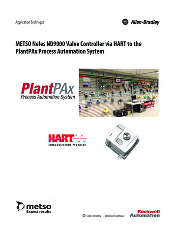
1756-DH485 Module Overview1-3External Features of the 1756-DH485 ModuleAlphanumericStatus leStatusIndicatorsChannel AConnectorChannel BConnector43842Prevent ElectrostaticDischargeThe DH-485 module is sensitive to electrostatic discharge.ATTENTION!This equipment is sensitive to electrostatic discharge, whichcan cause internal damage and affect normal operation.Follow these guidelines when you handle this equipment: Touch a grounded object to discharge potential static. Wear an approved grounding wriststrap. Do not touch connectors or pins on componentboards. Do not touch circuit components inside the equipment. Use a static-safe workstation, if available. Store the equipment in appropriate static-safepackaging when not in use,.Publication 1756-UM532A-EN-P - May 2006
1-41756-DH485 Module OverviewRemoval and InsertionUnder PowerYou can install or remove the module while chassis power is applied if youobserve the following precautions.WARNING!Publication 1756-UM532A-EN-P - May 2006When you insert or remove the module while backplanepower is on, an electrical arc can occur. This could cause anexplosion in hazardous location installations.Be sure that power is removed or the area is nonhazardousbefore proceeding. Repeated electrical arcing causesexcessive wear to contacts on both the module and itsmating connector. Worn contacts may create electricalresistance that can affect module operation.
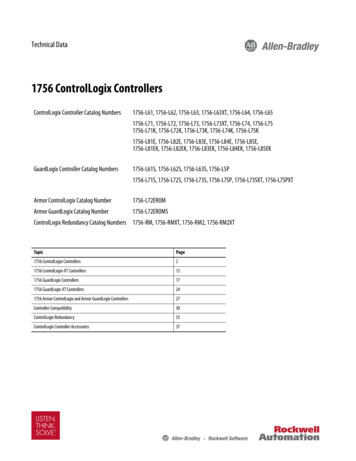
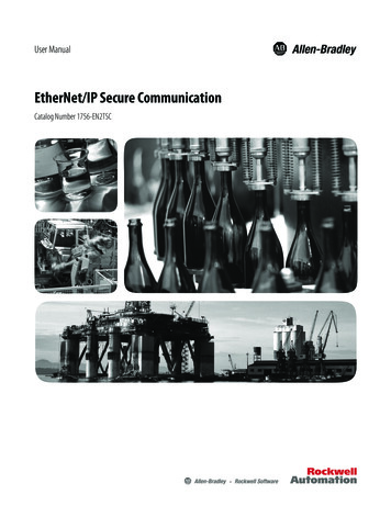
1756-DH485 Module Overview1-5The first example is a typical gateway application connecting multiple networkstogether.Typical ApplicationsIn this example you can: upload and download SLC 500 and Panelview display programs. seamlessly communicate between SLC controllers. connect multiple DH-485 networks together for inter-networkcommunications, for example, messages between SLC 5/03 controllers. provide connection to other NetLinx networks, such as EtherNet/IP, toallow a single-point access, for example: upload and download to anSLC controller, MicroLogix controller, and Panelview display.Connection of Multiple NetworksComputer with RSlogix 500and RSLogix 5000 Software1756-ENBT1756-DH485AIC Link CouplersAIC Link CouplerAIC Link CouplerAIC Link CouplerSLC 5/03 Controller44137PanelViewSLC 5/03 ControllerPublication 1756-UM532A-EN-P - May 2006
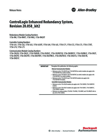
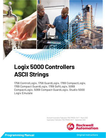
1-61756-DH485 Module OverviewThe second example shows how you can connect or migrate a legacy system toa new installation with RSLogix software. Connect multiple DH-485 networks together for inter-networkcommunications. Message between SLC 5/03 controllers. Provide connection to other NetLinx networks. Access through a single point and download to an SLC controller,MicroLogix controller, and Panelview display. Allow communications between legacy and ControlLogix systems forhigh integration of control systems (except for fixed SLC controllers). Phase SLC systems into ControlLogix architecture by using a migrationtool.Connect or Migrate a Legacy System to a New InstallationComputer with RSlogix 500and RSLogix 5000 SoftwareControlLogix ControllerControlLogix Controller1756-DH4851756-ENBT ModuleAIC Link CouplerAIC Link CouplerEX TERN A LEX TERN A LDH485 NetworkTERMAAIC AIC Link CouplerAIC Link CouplerMicroLogixAIC Link CouplerPanelView DisplaySLC 5/03 ControllerSLC 5/03 ControllerPublication 1756-UM532A-EN-P - May 200644136
1756-DH485 Module OverviewRemote Messaging1-7The configuration of remote messaging is similar to data highway remote I/O(DHRIO). It is achieved through routing table functions and moduleconfiguration. The multi-hop functionality is available in RSLogix 5 and 500(version 6.3 or later)Remote Upload and DownloadYou can bridge EtherNet/IP and ControlNet networks to a DH-485 networkusing the 1756-DH485 moduleYou can upload and download: all MicroLogix and SLC 500 controllers on DH-485 from NetLinxnetwork by using RSLinx Classic software. PanelView Standard terminals on DH-485 from NetLinx network byusing RSLinx Classic.Logix controllers message via a NetLinx network through a ControlLogixgateway to the DH-485 network to all MicroLogix and SLC 5/03 (and above)controllers on DH-485 network. RSLinx Classic software on the DH-485network can browse through the ControlLogix gateway to any device on aNetLinx network.IMPORTANTLogix controllers on a NetLinx network will not be able toinitiate messages through the ControlLogix gateway to theDH-485 network to fixed SLC 500, SLC 5/01, or SLC5/02 controllers on a DH-485 network.Publication 1756-UM532A-EN-P - May 2006
1-81756-DH485 Module OverviewThe 1756-DH485 module can route a message through up to fourcommunications networks and three chassis. This limit applies only to therouting of a message and not to the total number of networks or chassis in asystem.Routing LimitationsDH-485 and CIP MessagingThe 1756-DH485 module lets devices, such as ControlLogix, PLC, and SLCcontrollers exchange information. With the 1756-DH485 module, you mayexchange information between the ControlLogix, PLC, or SLC controllers ondifferent networks. Communication between SLC controllers on differentnetworks is accomplished using remote messaging.Communication Between SLC Controllers on Different NetworksData Collection andRecipe ManagementRSViewProgramming TerminalEtherNet/IP 5DH-485SLC 5/03PanelViewPublication 1756-UM532A-EN-P - May 2006MicroLogixSLC 5/03PanelView44056
1756-DH485 Module Overview1-9Alphanumeric IndicatorsWhen you apply power to the module, the alphanumeric display begins tocycle through the following sequence.1. All LEDs flash on then off -CHA, CHB OK2. OK displays red then changes to green.3. INIT displays.4. Firmware Revision flashes on scrolling display: DH-4855. Channel A and the network used for channel A.6. Channel A node address.7. Channel A status.8. Channel B and the network used for channel.9. Channel B node address.10. Channel B status.This sequence runs continuously during normal module operation.EXAMPLEFor example, if your module uses the following: Channel A for DH-485 with node address 14 Channel B is not connectedand the channels are operating properly, you see thefollowing sequence:A DH, A#14, A OK, B DH, B#00, ONLY NODERefer to Appendix B, Troubleshoot the 1756-DH485 Module and publication1756-IN587, the ControlLogix DH-485 Communications Module InstallationInstructions, for more information about LEDs and status indicators.Publication 1756-UM532A-EN-P - May 2006
1-101756-DH485 Module OverviewNotes:Publication 1756-UM532A-EN-P - May 2006
Chapter2Overview of the DH-485 NetworkIntroductionDH-485 NetworkDescriptionThe information in this chapter will help you plan, install, and operate deviceson a DH-485 network. This chapter also contains information that describesthe DH-485 network functions, network architecture, and performancecharacteristics.ForSeeDH-485 Network Description2-1DH-485 Network Protocol2-2DH-485 Token Rotation2-2DH-485 Network Initialization2-2Devices that Use the DH-485 Network2-31747-AIC Isolated Link Coupler for DH-4852-41761-NET-AIC Advanced Interface Converter Product Overview2-6Operating Modes2-6Device Compatibility2-61747-UIC USB to DH-485 Interface Converter2-7Example System Configuration2-8Important Planning Considerations2-10Additional Resources2-13The DH-485 network passes information between devices on the plant floor.The network monitors process parameters, device parameters, device status,process status, and application programs to support data acquisition, datamonitoring, program upload/download, and supervisory control.The DH-485 network offers: interconnection of 32 devices.multi-master capability.token passing access control.the ability to add or remove nodes without disrupting the network. maximum network length of 1219 m (4000 ft)(1).(1) The network can be extended to 2,438 meters (8,000 feet) by connecting two AIC Advanced InterfaceConverters (1761-NET-AIC). Refer to the AIC Advanced Interface Converter User Manual, publication number1761-6.4.1Publication 1756-UM532A-EN-P - May 2006
2-2Overview of the DH-485 NetworkThe protocol used to control message transfers on the DH-485 networksupports two classes of devices: initiators and responders. All initiators on thenetwork get a chance to initiate message transfers. To determine whichinitiator has the right to transmit, a token passing algorithm is used.DH-485 Network ProtocolA node holding the token is able to transmit a configurable number ofmessage packets (plus two retries) onto the network before having to pass thetoken on to the next node. This configuration parameter is called the TokenHold Factor and has a minimum value of one and a maximum value of four.Once a node holding the token has sent any messages that it has to send, up toits Token Hold Factor maximum allowed, it attempts to pass the token to itssuccessor by sending a token-pass packet.DH-485 Token RotationIf no network activity occurs, the initiator sends the token-pass packet again.After two retries (a total of three tries) the initiator will attempt to find a newsuccessor.IMPORTANTThe maximum address that the initiator will search forbefore wrapping to zero is the value in the configurableparameter maximum node address. The default value forthis parameter is 31 for all initiators and responders.The allowable range of the node address of an initiator is 0 to 31. Theallowable address range for all responders is 1 to 31. There must be at least oneinitiator on the network.DH-485 NetworkInitializationNetwork initialization begins when a period of inactivity exceeding the time ofa link dead timeout is detected by an initiator on the network. When the timefor a link dead timeout is exceeded, usually the initiator with the lowest addressclaims the token. When an initiator has the token it will begin to build thenetwork. The network requires at least one initiator to initialize it.Building a network begins when the initiator that claimed the token tries topass the token to the successor node. If the attempt to pass the token fails, orif the initiator has no established successor (for example, when it powers up), itbegins a linear search for a successor starting with the node above it in theaddressing.When the initiator finds another active initiator, it passes the token to thatnode, which repeats the process until the token is passed all the way aroundthe network to the first node. At this point, the network is in a state of normaloperation.Publication 1756-UM532A-EN-P - May 2006
Overview of the DH-485 NetworkDevices that Use theDH-485 Network2-3Presently, the following SLC 500 devices support the DH-485 network:Devices that Use the DH-485 NetworkCatalog blication1756-DH485ControlLogix DH485CommunicationModuleControlLogixChassisBridge DH485 messages in ControlLogix.1756-UM5321747-LxxxSLC 500ProgrammableControllersSLC ChassisProgrammable controllers.1747-UM0111747-KEDH-485/DF1Interface ModuleSLC ChassisProvides a non-isolated DH-485 interface forSLC 500 devices to host computers over RS-232using full- or DF1 half-duplex protocol. Enablesremote programming to an SLC 500 controller or theDH-485 network through modems. Ideal for low costRTU/SCADA applications.1747-IN0061747-UICUSB to DH-485Interface ConverterStandaloneProvides connection to personal computer’s USB port 1747-IN063and features an RS-232 and an RS-485 port forconnection to SLC 500 controllers.1747-AICIsolated Link Coupler StandaloneProvided connection to SLC 500 family devices to the 1747-UM011DH-485 network. The coupler provides a 6-positionremovable terminal block for connection to theDH-485 communication cable.1761-NET-AICAdvanced InterfaceConverterStandaloneProvides a communication link between variousnetworks devices.1761-UM0041770-KF3(1)DH-485/DF1Interface ModuleStandalone, ordesktopProvides an isolated DH-485 interface for SLC 500devices to host computers over RS-232 using full- orDF1 half-duplex protocol. Enables remoteprogramming to an SLC 500 controller or the DH-485network through modems.1770-6.5.181785-KA5DH /DH-485Gateway(1771) ovides communication between stations on thePLC-5 (DH ) and SLC 500 (DH-485) networks. Letscommunication and data transfer from PLC to SLC500 on DH-485 network. Also enables softwareprogramming or data acquisition across DH toDH-485.1784-KTX, 1784-KTXD PC DH-485 InterfaceCardISA BusProvides DH-485 or DH connection.1784-6.5.221784-PCMKPCMCIA InterfaceCardPCMCIA slot incomputerProvides DH-485 or DH e 11756-L1769-L1794-LLogix ProgrammableControllers1756 Chassis orDIN RailProgrammable on 1756-UM532A-EN-P - May 2006
2-4Overview of the DH-485 NetworkDevices that Use the DH-485 NetworkCatalog 2N(1),2707-M232P3(1), and2707-M485P3(1)DTAM Plus andDTAM MicroOperatorInterfaces(1)Panel MountProvides electronic operator interface for SLC 2,2711-K5A5,2711-B5A5,2711-K5A1,2711-B5A1,2711-K9A
i Publication 1756-UM532A-EN-P - May 2006 Preface Purpose of This Manual This manual describes how to understand, configure, and troubleshoot your ControlLogix Data Highway 485 communication interface module. This manual also provides step-by-step procedures on how to use the