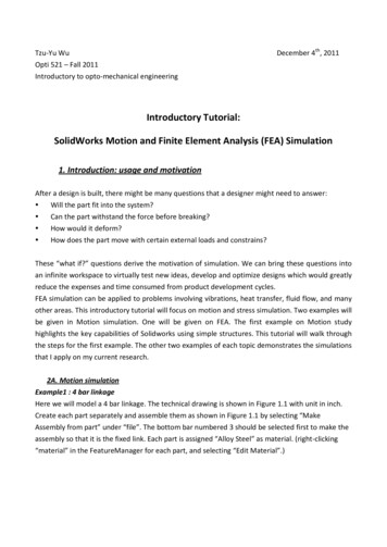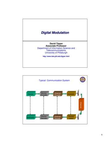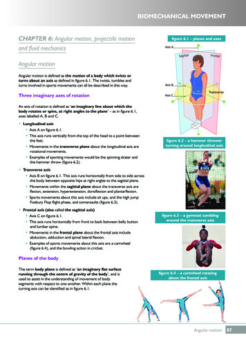
Transcription
User ManualSERCOS and Analog Motion Configuration and StartupCatalog Numbers 1756-HYD02, 1756-M02AE, 1756-M02AS, 1756-M03SE, 1756-M08SE, 1756-M16SE,1768-M04SE, 2094-SE02F-M00-S0, 2094-SE02F-M00-S1
Important user informationRead this document and the documents listed in the additional resources section about installation, configuration, and operation of this equipmentbefore you install, configure, operate, or maintain this product. Users are required to familiarize themselves with installation and wiring instructionsin addition to requirements of all applicable codes, laws, and standards.Activities including installation, adjustments, putting into service, use, assembly, disassembly, and maintenance are required to be carried out bysuitably trained personnel in accordance with applicable code of practice. If this equipment is used in a manner not specified by the manufacturer,the protection provided by the equipment may be impaired.In no event will Rockwell Automation, Inc. be responsible or liable for indirect or consequential damages resulting from the use or application of thisequipment.The examples and diagrams in this manual are included solely for illustrative purposes. Because of the many variables and requirements associatedwith any particular installation, Rockwell Automation, Inc. cannot assume responsibility or liability for actual use based on the examples anddiagrams.No patent liability is assumed by Rockwell Automation, Inc. with respect to use of information, circuits, equipment, or software described in thismanual.Reproduction of the contents of this manual, in whole or in part, without written permission of Rockwell Automation, Inc., is prohibited.Throughout this manual, when necessary, we use notes to make you aware of safety considerations.WARNING: Identifies information about practices or circumstances that can cause an explosion in a hazardous environment, which may lead topersonal injury or death, property damage, or economic loss.ATTENTION: Identifies information about practices or circumstances that can lead to personal injury or death, property damage, or economicloss. Attentions help you identify a hazard, avoid a hazard, and recognize the consequenceImportant:Identifies information that is critical for successful application and understanding of the product.Labels may also be on or inside the equipment to provide specific precautions.SHOCK HAZARD: Labels may be on or inside the equipment, for example, a drive or motor, to alert people that dangerous voltage may bepresent.BURN HAZARD: Labels may be on or inside the equipment, for example, a drive or motor, to alert people that surfaces may reach dangeroustemperatures.ARC FLASH HAZARD: Labels may be on or inside the equipment, for example, a motor control center, to alert people to potential Arc Flash. ArcFlash will cause severe injury or death. Wear proper Personal Protective Equipment (PPE). Follow ALL Regulatory requirements for safe workpractices and for Personal Protective Equipment (PPE).Allen-Bradley, Rockwell Software, Rockwell Automation, and TechConnect are trademarks of Rockwell Automation, Inc.Trademarks not belonging to Rockwell Automation are property of their respective companies.
Summary of changesThis manual contains new and updated information. The following table containsthe changes made to this revision.ChangeTopicUpdated the create a controller projectinformation.Create a controller project for Configure SERCOSMotion on page 21 andCreate a controller project for Configure AnalogMotion on page 43Rockwell Automation Publication MOTION-UM001D-EN-P - November 20153
Table of contentsPrefaceStudio 5000 environment . 13What you need . 13Configuration and start-up scenarios . 14Description of the modules . 14Help for selecting drives and motors . 15Where to find sample projects . 16Additional resources. 16Legal Notices. 18Chapter 1Configure SERCOS motionIntroduction for Configure SERCOS Motion . 21Create a controller project for Configure SERCOS Motion. 21Set time synchronization for Configure SERCOS Motion . 24Add a SERCOS motion module . 25Electronic Keying. 26Modify properties for a SERCOS motion module . 27More information. 29Add a SERCOS interface drive module. 29Modify properties for a SERCOS interface drive module . 31Add a motion group for Configure SERCOS Motion. 33Set the Base Update Period . 34Add an axis . 36Get axis information . 37Configure an axis for Configure SERCOS Motion . 38Set the homing sequence for Configure SERCOS Motion . 41Chapter 2Configure analog motionIntroduction for Configure Analog Motion . 43Create a controller project for Configure Analog Motion . 43Set time synchronization for Configure Analog Motion. 46Add an analog module . 47Modify properties for an analog module . 48Add a hydraulic drive module . 51Modify properties for a hydraulic drive module . 52Configure the feedback type . 54Add a motion group for Configure Analog Motion . 55Set the Base Update Period . 56Add an axis for Configure Analog Motion . 57Rockwell Automation Publication MOTION-UM001D-EN-P - November 20155
Table of contentsGet Axis Information. 58Configure an axis for Configure Analog Motion . 59Set the homing sequence for Configure Analog Motion. 60Chapter 3Commission and tuneIntroduction for Commission and Tune . 61Download a program to the controller . 61Test axis wiring and direction . 61Tune a SERCOS axis . 63Tune an analog axis . 64Troubleshoot faults . 64Manage motion faults . 65Configure the fault actions for an axis . 66Set the fault action for an axis . 67Inhibit an axis . 67When to inhibit an axis . 67Example 1 . 68Example 2 . 68Before you begin . 68Example: Inhibit an axis . 70Example: Uninhibit an axis . 71Test an axis with Motion Direct Commands. 72Access the Motion Direct Commands for a motion group . 73Access the Motion Direct Commands for an axis. 73Choose a command . 74Motion Direct Command dialog box . 76Motion Group Shutdown . 77Motion Direct Command error process . 78Motion Direct Command verification . 78Motion Direct Command execution error . 80What if the software goes offline or the controller changes modes? . 80Can two workstations give Motion Direct Commands?. 80Chapter 4Program6Introduction . 83Definition of Jerk . 83Choose a profile . 83Use % of Time for the easiest programming of jerk . 84Velocity Profile Effects . 85Jerk Rate Calculation. 86Rockwell Automation Publication MOTION-UM001D-EN-P - November 2015
Table of contentsProfile operand . 90Enter basic logic. 94Example: Motion control program. 95Download a program and run the logic . 96Choose a motion instruction . 96Sample projects . 98Troubleshoot axis motion . 99Why does my axis accelerate when I stop it? . 99Why does my axis overshoot its target speed? . 102Why is there a delay when I stop and then restart a jog? . 105Why does my axis overshoot its position and reverse direction? . 107Chapter 5Home an axisIntroduction for Home an Axis. 111Guidelines for homing . 111Active homing . 112Passive homing . 112Absolute homing . 113Examples . 113Active homing examples . 113Passive homing examples . 119Homed Status. 119Feedback Integrity . 120Appendix AAxis propertiesIntroduction for Axis Properties . 121General tab – AXIS SERVO . 121General tab - AXIS SERVO DRIVE . 122Node with a Kinetix 6000 drive . 123General tab - AXIS VIRTUAL . 124Motion Group. 124MOTION GROUP structure . 124General tab – AXIS GENERIC . 126Motion Planner tab . 126Units tab . 128Servo tab - AXIS SERVO . 128Feedback Tab – AXIS SERVO . 129Drive/Motor tab - AXIS SERVO DRIVE . 132Motor Feedback tab - AXIS SERVO DRIVE . 137Aux Feedback tab - AXIS SERVO DRIVE . 137Rockwell Automation Publication MOTION-UM001D-EN-P - November 20157
Table of contentsConversion tab . 138Homing tab - AXIS SERVO . 140Homing tab - AXIS SERVO DRIVE. 142Homing tab - AXIS VIRTUAL. 144Hookup tab - AXIS SERVO . 145Hookup tab - AXIS SERVO DRIVE. 146Test Increment . 147Drive Polarity . 147Test Marker . 147Test Feedback . 148Test Command & Feedback . 148Tune tab - AXIS SERVO, AXIS SERVO DRIVE . 148Travel Limit . 148Speed . 149Torque/Force (AXIS SERVO DRIVE) . 149Torque (AXIS SERVO) . 149Direction . 149Damping Factor . 150Tune . 150Start Tuning . 151Dynamics tab - AXIS SERVO, AXIS SERVO DRIVE,AXIS VIRTUAL . 152Maximum Speed . 152Maximum Acceleration. 153Maximum Deceleration . 153Maximum Acceleration Jerk . 153Maximum Deceleration Jerk. 154Calculate button . 154Manual Adjust. 155Gains tab - AXIS SERVO . 156Proportional (Position) Gain . 156Integral (Position) Gain . 157Differential. 158Proportional (Velocity) Gain. 158Integral (Velocity) Gain . 158Velocity Feedforward. 159Acceleration Feedforward. 159Integrator Hold. 159Manual Adjust. 160Gains Tab - AXIS SERVO DRIVE . 160Velocity Feedforward. 161Acceleration Feedforward. 1628Rockwell Automation Publication MOTION-UM001D-EN-P - November 2015
Table of contentsProportional (Position) Gain . 162Integral (Position) Gain . 162Proportional (Velocity) Gain. 163Integral (Velocity) Gain . 164Integrator Hold. 164Manual Adjust. 165Set custom gains . 165Attribute . 165Output tab - AXIS SERVO . 166Velocity Scaling . 167Torque/Force Scaling . 167Direction Scaling Ratio . 168Enable Low Pass Output Filter . 168Low-pass Output Filter Bandwidth . 168Manual Adjust. 169Output tab - AXIS SERVO DRIVE . 169Motor Inertia. 170Load Inertia Ratio . 170Torque/Force Scaling . 170Enable Notch Filter Frequency . 171Notch Filter Frequency . 171Enable Low Pass Output Filter . 171Low-pass Output Filter Bandwidth . 171Manual Adjust. 172Limits tab - AXIS SERVO . 172Soft Travel Limits . 173Maximum Positive . 173Maximum Negative. 173Position Error Tolerance . 174Position Lock Tolerance . 174Output limit . 174Manual Adjust. 175Limits tab - AXIS SERVO DRIVE . 175Hard Travel Limits . 176Soft Travel Limits . 176Maximum Positive . 176Maximum Negative. 176Position Error Tolerance . 177Position Lock Tolerance . 177Peak Torque/Force Limit . 177Continuous Torque/Force Limit . 177Manual Adjust. 178Rockwell Automation Publication MOTION-UM001D-EN-P - November 20159
Table of contentsSet custom limits. 178Attributes . 179Offset tab - AXIS SERVO. 180Friction/Deadband Compensation and Backlash Compensation . 181Backlash Compensation Window . 182Backlash Compensation and Backlash Reversal Offset . 182Stabilization Window . 183Velocity Offset . 183Torque Offset . 183Output Offset . 183Manual Adjust. 184Offset tab - AXIS SERVO DRIVE . 184Backlash Compensation. 185Backlash Compensation Window . 185Backlash Compensation and Backlash Reversal Offset . 186Stabilization Window . 186Velocity Offset . 186Torque/Force Offset . 187Manual adjust for Offset tab . 187Fault Actions tab - AXIS SERVO . 187Drive Fault . 189Feedback Noise . 189Feedback Loss . 189Position Error . 189Soft Overtravel . 189Fault Actions tab - AXIS SERVO DRIVE . 190Drive Enable Input. 191Drive Thermal . 191Motor Thermal . 192Feedback Noise . 192Feedback . 192Position Error . 192Hard Overtravel. 192Soft Overtravel . 192Phase Loss. 193Set custom stop action . 193Attributes . 193Tag tab. 195Name . 195Description . 195Tag Type. 195Data Type . 19510Rockwell Automation Publication MOTION-UM001D-EN-P - November 2015
Table of contentsScope . 196Style . 196Monitoring axis tags . 196Create reports . 196Appendix BMotion axis attributesIntroduction for Motion Axis Attributes . 199Accessing an MSG instruction . 199Interpreting the Attribute Tables . 199Replicated Attributes. 200Axis attributes . 201Additional error code information . 293Appendix CW
User Manual SERCOS and Analog Motion Configuration and Startup Catalog Numbers 1756-HYD02, 1756-M02AE, 1756-M02AS, 1756-M03SE, 1756-M08SE, 1756-M16SE,
