Transcription
California High-Speed Train ProjectCALIFORNIAWithout ever leaving the ground.TECHNICAL MEMORANDUMTraction Power FacilitiesGeneral Standardization RequirementsTM 3.1.1.3Prepared by:Signed document on fileVinod Sibal04 Jun 10DateChecked by:Signed document on fileRichard Schmedes07 Jun 10DateApproved by:Signed document on fileKen Jong, PE, Engineering Manager10 Jun 10DateReleased by:Signed document on fileAnthony Daniels, Program Director11 Jun 10DateRevision01Date01 Aug 0803 Jun 09210 Jun 10DescriptionInitial Release, R0Paralleling Station sites revised to be at five-mileintervals; agency terminology updatesUpdate Traction Power Facility footprint requirement,abbreviation updates, and additional requirements addedNote: Signatures apply for the latest technical memorandum revision as noted above.Prepared byfor the California High-Speed Rail Authority
California High-Speed Train ProjectTraction Power Facilities, R2This document has been prepared by Parsons Brinckerhoff for the CaliforniaHigh-Speed Rail Authority and for application to the California High-Speed TrainProject. Any use of this document for purposes other than this Project, or thespecific portion of the Project stated in the document, shall be at the sole risk ofthe user, and without liability to PB for any losses or injuries arising for such use. i CALIFORNIACALIFORNIA HIGH-SPEED RAIL AUTHORITY
California High-Speed Train ProjectTraction Power Facilities, R2System Level Technical and Integration ReviewsThe purpose of the review is to ensure:- Technical consistency and appropriateness- Check for integration issues and conflictsSystem level reviews are required for all technical memorandums. Technical Leads for eachsubsystem are responsible for completing the reviews in a timely manner and identifyingappropriate senior staff to perform the review. Exemption to the system level technical andintegration review by any subsystem must be approved by the Engineering Manager or theSystem Integration Manager.System Level Technical Reviews by Subsystem:Systems:NOT REQUIREDPrint Name:DD Month YYDateInfrastructure:Signed document on fileJohn Chirco23 May 10DateOperations:NOT REQUIREDPrint Name:DD Month YYDateMaintenance:NOT REQUIREDPrint Name:DD Month YYDateRolling Stock:NOT REQUIREDPrint Name:DD Month YYDateNote: Signatures apply for the technical memorandum revision corresponding to revision number in header and as noted on cover.'qi ---- CALIFORNIAPage i
California High-Speed Train ProjectTraction Power Facilities, R2TABLE OF CONTENTSABSTRACT . 11.0INTRODUCTION . 21.11.21.32.0DEFINITION OF TECHNICAL TOPIC . 52.13.0GENERAL . 7SOURCE INFORMATION AND REFERENCES . 95.16.0GENERAL . 6ASSESSMENT . 63.2.1 Analysis . 63.2.2 CHSTP Standard . 6SUMMARY AND RECOMENDATIONS . 74.15.0GENERAL . 52.1.1 CHSTP System Design Considerations . 52.1.2 CHSTP System Design Parameters . 5ASSESSMENT / ANALYSIS . 63.13.24.0PURPOSE OF TECHNICAL MEMORANDUM . 2STATEMENT OF TECHNICAL ISSUE . 2GENERAL INFORMATION . 21.3.1 Definition of Terms . 21.3.2 Units . 4GENERAL . 9DESIGN MANUAL CRITERIA . 106.16.2TRACTION POWER FACILITIES GENERAL STANDARDIZATION REQUIREMENTS . 106.1.1 Footprint . 106.1.2 Equipment and Vehicle Access . 106.1.3 Approximate Spacing . 106.1.4 Maximum Distance from Right of Way . 106.1.5 Additional Requirements . 106.1.6 Location along the Right of Way . 11W AYSIDE POWER CONTROL CUBICLES (WPC) . 11'qi ---- CALIFORNIAPage ii
California High-Speed Train ProjectTraction Power Facilities, R2ABSTRACTIn order to provide a dependable and cost effective traction power supply system (TPS) for theCalifornia High-Speed Train Project (CHSTP) the placement, size, and power conditioning of thetraction power facilities (TPF) will be a priority during all phases of the design process. Toenhance safe working conditions, simplify Operating and Maintenance procedures, and minimizethe number and type of spare parts required, the layout and rating of the traction power facilitieswill be standardized as much as is feasible.The purpose of this technical memorandum is to review best practices and provide designrequirements that specify these standardization requirements, and to list applicable industrystandards, codes, and guidelines to: Define the physical footprint of each type of traction power facility (substation - SS withhigh voltage utility circuits, switching station - SWS, and paralleling station - PS).Define the land needed to be obtained to allow installation of each type of traction powerfacility.Note: All TPF must preferably, be located within 100 feet of the CHSTP alignment tominimize the length of the duct banks between the TPF and the track. Define the requirements for access and maintenance of the TPF.Allow for the consistent sizing and standardization of all TPF equipment includingtransformers, switchgear, and bus systems.Allow for standardized duct banks and cable sizing, and routingNote: The last two items are not discussed in the text and will be defined and discussedwhen the traction power equipment is identified.Development of the general design criteria for the traction power supply system will includereview and assessment of, but not limited to, the following: Standardized layouts and equipment configurations for each type of traction powerfacility. Size of sites required for each type of traction power facility, including vehicle access.Existing FRA, CPUC General Orders, NESC, IEEE, NFPA, and AREMA guidelines whereapplicable to the traction power facility equipment and sites.The gathering and analysis of existing international standards, codes, best practices, andguidelines used on existing high-speed train systems for applicability to CHSTP tractionpower facilities. V171 ---- CALIFORNIAPage 1
California High-Speed Train ProjectTraction Power Facilities, R21.0 INTRODUCTIONThe California High-Speed Rail Authority (CHSRA) is in the process of designing and building aworld class high-speed train system to connect the major cities of California. In the finalalignment for the California High Speed Train Project (CHSTP), consideration must be given tothe availability of the space required to accommodate the three types of traction power facilities(TPF) namely, substations, switching stations and paralleling stations. The space, electricalfeeds, and proximity to the alignment has been addressed in an effort to standardize these sitesas much as possible. Standardization will shorten the design time; however, the dimensions ofavailable sites and their orientation to the rail right-of-way (ROW) and adjacent roadways mayrequire site specific layouts to be developed.This memorandum defines general space requirements for each of the three types of sitesrequired on the CHSTP, i.e., substation with high voltage utility circuits, switching station, andparalleling station. This includes site requirements such as access for initial site work andequipment installation, parking for maintenance vehicles, and access for emergency vehicles.A definition of generic footprints for each type of TPF has been given as well as the conceptuallayout of the major items of equipment. The dimensions of specific equipment has not beenincluded as a part of this memorandum but sizing of the station sites takes into consideration thelargest equipment sizes presently used in similar high-speed rail systems.1.1PURPOSE OF TECHNICAL MEMORANDUMThe purpose of this document is to define space and equipment requirements for each of thethree types of traction power facilities.1.2STATEMENT OF TECHNICAL ISSUEIn order for the section designers for each segment of the California High-Speed Train Project toassess the land requirements for the traction power supply system (TPS), this memorandumaddresses the footprint of each type of TPF, the access requirements for installation,maintenance and emergency vehicles, and any other areas that might be need to be consideredat individual sites.NOTE: All TPF should preferably, be located within 100 feet of the high-speed rail alignment tominimize the length of the duct banks between the TPF and the track.1.3GENERAL INFORMATIONThe CHSTP will have an end-to-end length of approximately 800 miles. It will be designed andbuilt in segments, possibly by different entities, over a number of years. Although the civil andstructural elements of the line may vary in the different segments, the “system” elements must beconsistent over the full length of the line. This technical memorandum provides the basicinformation and criteria to be used for the TPF sites and equipment layout. This information isapplicable to all main line segments of the CHSTP.1.3.1Definition of TermsThe following technical terms, acronyms, phrases, and terminology have specific connotationswith regard to traction power supply system for the California High-Speed Train Project: Technical TermsAutotransformer (AT): Apparatus which helps boost the OCS voltage and reduce therunning rail return current in the 2 X 25 kV autotransformer feed configuration. It uses asingle winding having three terminals. The intermediate terminal located at the midpointof the winding is connected to the rail and the two outer terminals are connected to thecatenary and negative feeder wires.V171 ---- CALIFORNIAPage 2
California High-Speed Train ProjectTraction Power Facilities, R2Negative Feeder (NF): Negative feeder is an overhead conductor supported on the same0structure as the OCS, and is at a voltage 25 kV with respect to ground but 180 out-ofphase with respect to the voltage on the OCS, i.e. the voltage between the OCS and thenegative feeder is 50 kV nominal. The negative feeder connects successive feedingpoints, and is connected to one terminal of an autotransformer in the traction powerfacilities via a circuit breaker or disconnect switch. At these facilities, the other terminal ofthe autotransformer is connected to a catenary section or sections, via circuit breakers ordisconnects.Power Transformer: A device which transforms power on an AC system from one voltagelevel to another (e.g., from 115 kV to 25 kV).Traction Power Facilities (TPF): A general term that encompasses substations (SS),switching stations (SWS) and paralleling stations (PS).Traction Power Supply System (TPS): The railway electrical distribution network used toprovide energy to high-speed electric trains, which comprises of the following three typesof traction power facilities in addition to connections to the OCS and the traction returnand grounding system:1. Substation (SS) at which power is converted from high voltage to a nominal 2X25kV railway traction voltage and distributed to the overhead contact system (OCS)and the negative feeders, including incoming high voltage (115/230 kV) supplies frompower supply utility’s network,2. Switching Station (SWS): An installation at which electrical energy can be suppliedto an adjacent, but normally separated electrical section during contingency powersupply conditions. It also acts as a PS, and3. Paralleling Station (PS): An installation which helps boost the OCS voltage andreduce the running rail return current by means of the autotransformer feedconfiguration. The negative feeders and the catenary conductors are connected tothe two outer terminals of the autotransformer winding at this location. OCS sectionscan be connected in parallel at PS locations.Wayside Power Control Cubicle (WPC): A wayside installation that houses remoteterminal unit (RTU) and dc power supply unit for motor operated disconnect switches atlocations other than traction power facilities. VMWNFV171 ---- CALIFORNIAAlternating CurrentAluminium Conductor Steel ReinforcedAerial Earth (Ground) ConductorAutotransformerBuried Earth (Ground) ConductorCalifornia High Speed Rail AuthorityCalifornia High Speed Train ProjectCalifornia Public Utility CommissionCopperContact WireDirect CurrentHard DrawnHigh VoltageImpedance BondLow VoltageMessenger WireNegative FeederPage 3
California High-Speed Train Project1.3.2Traction Power Facilities, R2NISTOCSPG&EPSSCESDBSDG&ESSSWSTPFTPSNational institute of Standards and TechnologyOverhead Contact SystemPacific Gas and Electric CompanyParalleling Station with Autotransformer(s)Southern California EdisonSystem Duct BankSan Diego Gas and ElectricSubstation (with HV Utility Supply)Switching Station with Autotransformer(s)Traction Power Facility (ies)Traction Power Supply SystemWPCWayside Power Control CubicleUnitsThe California High-Speed Train Project (CHSTP) is based on U.S. Customary Units consistentwith guidelines prepared by the California Department of Transportation and defined by theNational Institute of Standards and Technology (NIST). U.S. Customary Units are officially usedin the United States, and are also known in the U.S. as “English” or “Imperial” units. In order toavoid confusion, all formal references to units of measure should be made in terms of U.S.Customary Units.'qi ---- CALIFORNIAPage 4
California High-Speed Train ProjectTraction Power Facilities, R22.0 DEFINITION OF TECHNICAL TOPIC2.1GENERALThe following sections contain the design considerations that were assessed in determining theland space requirements to be used for the CHSTP TPF sites, and the local, state, or federalcodes that each site must meet.2.1.1CHSTP System Design ConsiderationsThe CHSTP system will require locating acceptable plots of land for the construction of andaccess to three types of TPF. This memorandum considers existing high-speed train systemsaround the world and their TPF equipment. It also highlights that local, state, and federalemergency vehicle code requirements as applicable and maintenance vehicle accessrequirements must be investigated for each individual site. The TPF sites have been sized toinclude: Substation with HV utility supply circuits and switchgearSwitching Stations with autotransformers Paralleling Stations with autotransformersWith these “standardized” traction power facility footprints, where site conditions permit, thesegment designers will be able design the ductbanks, cable sizing, and cable routing in a waythat allows a repetitive design and standardization of equipment locations throughout the CHSTP.While the specifics of the equipment are not known at this time, installed equipment will includebut not be limited to:2.1.2 Power TransformersAutotransformersStation Service Transformers/Auxiliary TransformersCircuit Breakers Disconnect SwitchesBus Bar SystemsSwitchgear RoomsControl Rooms Control PanelsMetering Cable Trays/DuctingGround Grids FencingCHSTP System Design Parameters Nominal system voltage – 25kVMinimum utility supply voltage – 115 kV at SSRedundant utility supply at SS Redundant power supply transformers at SSNo degradation of train performance during Single Contingency Power Supply conditionsNo stranded trains during Second Contingency Power Supply conditionsLocal, state, and federal emergency vehicle access requirementsOperation and maintenance access requirements Traction power facility spacing requirements along right-of-way (each station type)'qi ---- CALIFORNIAPage 5
California High-Speed Train ProjectTraction Power Facilities, R23.0 ASSESSMENT / ANALYSIS3.1GENERALTraction power facility locations and sizes are critical to segment designers in their search foradequate land close to the CHSTP alignment, and for substations’ access to HV utility supplycircuits. The attached drawings define the site size requirements for each type of TPF and showa conceptual layout for equipment and vehicle access.Note: The drawings show both the minimum dimensions of the fenced area required for theconceptual layout shown and the proposed dimensions for a typical site.3.2ASSESSMENT3.2.1AnalysisThe information included in this technical memorandum is to allow the definition of land spaceand access required along the right-of-way to allow the construction and maintenance of the threetypes of traction power facilities required for the traction power supply system. The site sizingwas based on: HV utility supply circuits for the supply stations 115kV or higher Each substation having redundant HV utility supply circuits originating from differentsources Each substation having redundant power supply transformers each sized for the full-loadof the substationSwitching stations having four autotransformersParalleling stations having two autotransformersSubstation, switching stations, and paralleling stations rated and located in accordancewith the findings of the traction power supply computer load-flow simulations Traction power facility ratings and configuration for each type of station, i.e., substation,switching station, and paralleling station, being standardized as much as is feasible The ultimate level of service to be supported by each section of the traction power supplysystem. The location of existing HV utility circuitsThe location and availability of acceptable sites for the TPF.Site areas preferably, within 100’ of CHSTP alignment Provision of a separate communications room (20’ x 15’) within and on the periphery ofevery TPF to house communications interface equipment for SCADA system and otherwayside communications equipment, with a separate accessAvailable sites will be verified as being acceptable locations when traction power simulations areperformed and the required performance of the traction power supply system is demonstrated.3.2.2CHSTP StandardBecause at this time there are no specific North American Federal or State of Californiastandards or criteria for 25kV, 60 Hz electrification systems, the criteria of other countries’ highspeed rail systems, NESC, NFPA 130, State of California Public Utility Commission (CPUC)General Orders (GO), and CFR 46 requirements were reviewed during the development of thistechnical memorandum.V171 ---- CALIFORNIAPage 6
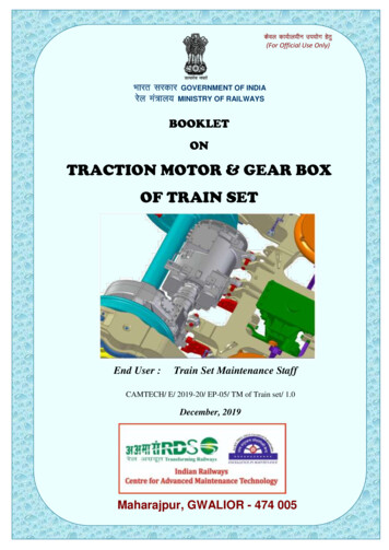
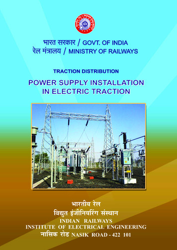
California High-Speed Train ProjectTraction Power Facilities, R24.0 SUMMARY AND RECOMENDATIONS4.1GENERALIt is recommended that the following general dimensions be used for the sites for each type oftraction power facility: Traction power substation with two power transformers (Figure 1):200 ft X 160 ft Traction power substation with three power transformers (Figure 2):200 ft X 210 ft Traction power switching station (Figure 3):160 ft X 90 ft Traction power paralleling station (Figure 4):120 ft X 80 ftAs a general guideline for locating sites: The candidate locations should be assessed and environmentally cleared for a larger sitethan the recommended general dimensions to accommodate refinement of site layout insubsequent design phases.Substation sites should be spaced approximately every 30 miles. Switching station sites should be located approximately midway between substationsites. Paralleling station sites should be located at approximately five-mile intervals betweenswitching station and substation sites. In general, all substations will be configured with two power transformers although theremay be some locations that shall require a substation configuration with three powertransformers. With a view to preventing stalling of trains at the phase-breaks, substations and switchingstations should preferably not be located within a 2-mile distance from the nearest end ofany railway station or wayside crossover. These are typical footprints of different traction power facilities. Orientation of the TPFwith respect to tracks, locations of utility supply circuits, equipment, and road access shallbe determined on a site-by-site basis. Added space may be required adjacent to the substation site if HV supply circuits mustbe constructed to serve the site. These requirements have been detailed in another TM(TM 3.1.5.3). Access to each site will be required both during construction and for operating andmaintenance purposes. Heavy equipment must be installed initially and may be replacedduring service. Access roads between public roadways and each TPF site shall be constructed andconfigured to allow periodic access to low-load type vehicles, and routine access andparking for maintenance type vehicles. If the traction power facility has to be located in the proximity of or beneath high-speedtrain tracks located on aerial guideways it shall be ensured that the main powertransformers and autotransformers are located in an open area (shall not be locatedunderneath structures), and that proper clearances are available for the main gantry(main gantry dimensions are given in the above four drawings). There shall be a strain gantry located within the railroad right-of-way (ROW) parallel toand on the opposite side of the track away from the TPF, with footprints exactly equal tothat of the main gantry (main gantry dimensions are given in the above four drawings). If the TPF is located away from the track, the main gantry will be located within therailroad ROW, parallel to and towards TPF side of the track. In this case an additionalstrip of land (40’ wide for SS and SWS, and 30’ wide for PS) will be required for laying'qi ---- CALIFORNIAPage 7
California High-Speed Train ProjectTraction Power Facilities, R2duct banks and manholes for laying power cables from the TPF to the main gantry.Typical layouts of duct banks and manholes and conceptual TPF locations are presentedin the following drawings:-Typical Duct Bank Details (Figure 5)-Typical manhole Details (Figure 6), and-Alternative Conceptual Locations of Traction power facilities Relative to RailroadROW (Figure 7).In addition to these TPF there will be many wayside power control cubicles (WPC) located atrailway stations and on the wayside. Footprints of WPC are given in TM 3.3.2 (Directive DrawingsTM 3.3.2 – A and TM 3.3.2 – B)'qi ---- CALIFORNIAPage 8
California High-Speed Train ProjectTraction Power Facilities, R25.0 SOURCE INFORMATION AND REFERENCES5.1GENERAL1.2.3.4.5.6.7.8.9.French TGV SystemJapanese Shinkansen SystemTaiwan HSR SystemGerman ICE-3 HSR SystemNEC, Boston to New Haven Electrified LineCaltrain Electrification Project Design DocumentsNational Electrical Safety CodeIEEE – 80: Guide for Safety in AC Substation GroundingCalifornia Public Utilities Commission (CPUC) General Orders'qi ---- CALIFORNIAPage 9
California High-Speed Train ProjectTraction Power Facilities, R26.0 DESIGN MANUAL CRITERIA6.1TRACTION POWER FACILITIES GENERAL STANDARDIZATION REQUIREMENTS6.1.1FootprintApproximate footprints for the traction power facilities:1. Traction power substation (2 power transformers) with two high voltage utility supply circuits –200 ft X 160 ft2. Traction power substation (3 power transformers) with two high voltage utility supply circuits –200 ft X 210 ft3. Traction power switching stations with 4 - 2 x 25kV autotransformers – 160 ft X 90 ft4. Traction power paralleling stations with 2 – 2 x 25kV autotransformers – 120 ft X 80 ftThese are typical footprints of different traction power facilities. Orientation of the TPF withrespect to tracks, locations of utility supply circuits, equipment, and road access shall bedetermined on a site-by-site basis.In general, all substations will be configured with two power transformers although there may besome locations that shall require a substation configuration with three power transformers.6.1.2Equipment and Vehicle AccessAccess to each site shall be required both during construction and for operation and maintenancepurposes. Access roads between public roadways and each TPF site shall be constructed andconfigured to allow periodic access to low-load type of vehicles, and routine access and parkingfor maintenance type vehicles. The conceptual layouts of equipment and vehicle access areshown in Figures 1 4.6.1.3Approximate Spacing1. Substation sites at 30 mile intervals along the HSR right-of-way2. Switching station sites midway between substation sites3. Paralleling station Sites at approximately five-mile intervals between switching station andsubstation sites4. With a view to preventing stalling of trains at the phase-breaks, substations and switchingstations should preferably not be located within a 2-mile distance from the nearest end of anyrailway station or wayside crossover.6.1.4Maximum Distance from Right of WayThe trackside fence for all types of traction power facilities should preferably be located not morethan 100 feet from the CHSR right of way.6.1.5Additional Requirements1. The candidate locations should be assessed and environmentally cleared for a larger sitethan the recommended general dimensions to accommodate refinement of site layout insubsequent design phases.2. Added space may be required adjacent to the substation site if HV supply circuits must beconstructed to serve the site. These requirements have been detailed in another TM (TM3.1.5.3).3. If the traction power facility has to be located in the proximity of or beneath high-speed traintracks located on aerial guideways it shall be ensured that that the main power transformersand autotransformers are located in an open area (shall not be located underneath'qi ---- CALIFORNIAPage 10
California High-Speed Train ProjectTraction Power Facilities, R2structures), and that proper clearances are available for the main gantry (main gantrydimensions are given in the above four drawings).4. Where practical, Candidate sites should be on a level grade to eliminate need for extensive gradingand construction of retaining walls Candidate sites should be located away from residential property Roadways access should be provided between the TPF and the high-speed trainsROW to allow for consolidation of maintenance and emergency access locations.5. There shall be a strain gantry located within the railroad right-of-way (ROW) parallel to andon the opposite side of the track away from the TPF, with footprints exactly equal to that ofthe main gantry (main gantry dimensions are given in the above four drawings).6. If the TPF is located away from the track, the main gantry will be located within the railroadROW, parallel to and towards TPF side of the track. In this case an additional strip of land(40’ wide for SS and SWS, and 30’ wide for PS) will be required for laying duct banks andmanholes for laying power cables from the TPF to the main gantry. Typical layouts of ductbanks and manholes and conceptual TPF locations are presented in the following drawings:6.1.6 Typical Duct Bank Details (Figure 5) Typical manhole Details (Figure 6), and Alternative Conceptual Locations of Traction power facilities Relative to Railroad ROW(Figure 7).Location along the Right of WayOnce preliminary site locations have been selected Traction Power Simulations will be performedto confirm that the spacing and locations are acceptable for the required performance of theTraction Power Supply System.6.2WAYSIDE POWER CONTROL CUBICLES (WPC)In addition to these TPF there will be many wayside power control cubicles (WPC) located atrailway stations and on the wayside. The requirement and the footprints of WPC are given in TM3.3.2 (Directive Drawings TM 3.3.2 – A and TM 3.3.2 – B). Every WPC shall have a footprint of10’ x 8’. The number of WPC shall be as following: At every railway station including the universal crossovers on both ends – 6 At every wayside universal crossover – 1'qi ---- CALIFORNIAPage 11
California High-Speed Train ProjectTraction Power-Supply Sites, R2 1.TH[ S IS A T'tP[CA.L LAYOUT AND THE ORIENTA.TION OF THE STATlONWITH RESPECT TO TR.ACK, LOC
switching stations (SWS) and paralleling stations (PS). Traction Power Supply System (TPS): The railway electrical distribution network used to provide energy to high-speed electric trains, which comprises of the following three types of traction power facilities in addition to connections to the OCS and the traction return and grounding system: 1.