Transcription
PREFACEThe book on "Power Supply Installation in Electrical Traction" wasbrought out by Institution of Railway Electrical Engineers (IREE) long back.Since, lot of changes have taken place in the field of Power SupplyInstallation, it has become necessary to incorporate the changes in thisvolume. Few additions and modifications in the field of Power SupplyInstallations are included in this book.For bringing out this book Shri M.K.Jain, Section Engineer(TRD) andShri Suryawanshi M.A., Raj Bhasha Supdtt. have made substantial efforts,under the guidance of Shri R.B.Bhargav, Professor (TRD).I am delighted to note that lot of efforts have been undertaken inbringing out this book of "Power Supply Installations in Electrical Traction"in the present form. I am sure that this book will serve the needs ofElectrical Engineers working in the field of Power Supply Installations inElectrical Traction.Nasik Road21st May, 2010A.K.RAWALDIRECTOR
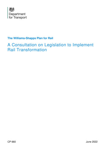
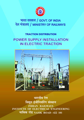
1. GENERAL DESCRIPTION OF FIXED INSTALLATIONS1.0POWER SUPPLY ARRANGEMENTS AT SUB-STATIONS1.0.1. Power Supply25 kV, AC, 50 Hz single phase power supply for electric traction is derivedfrom the grid of State Electricity Boards through traction sub-stations located alongthe route of the electrified sections at distance of 35 to 50 km apart. The distancebetween adjacent substations may however be even less depending on intensity oftraffic and load of trains.At present there are broadly four different arrangement in existence as under1.The Supply Authorities supply power at 220/132/110/66 kV Extra HighVoltage (EHV) at each traction substation which is owned, installed,operated and maintained by the Railways.2.The Railway receives 3-phase power supply from the supply Authorityat a single point near the grid substation from where the Railway runsits own transmission lines providing its own traction sub-stations.3.All EHV and 25 kV equipment is owned, installed, operated andmaintained by the Supply Authority except 25 kV feeder circuitbreakers which are owned, installed, operated and maintained by theRailway.4.All EHV and 25 kV equipment is owned, installed, operated andmaintained by the Supply Authority but 25 kV feeder circuit breakersalone are operated on remote control by the Traction Power Controller(TPC).1.0.2 Duplicate Supply1.Fig 2.01 shows schematically the arrangement at a typical traction substation.2.To ensure continuity of supply under all conditions, the high voltagefeed to the traction substations is invariably arranged wither from twosources of power or by a double transmission line, so that if onesource fails the other remains in service. Suitable protective equipmentis installed at the substations to ensure rapid isolation of any fault intransmission lines and substation equipment, so that the power supplyfor electric traction is maintained under all conditions.3.At each traction substation, normally two single phase transformers areinstalled, one which is in service and the other is 100% stand by. Thepresent standard capacity is 21.6 MVA (ONAN)/30.2 MVA (ONAF).1
However transformers of capacity 13.5 MVA (ONAN)/10.8 MVA(ONAN) have also been used at many of the substations. Thesetransformers step down the grid voltage to 25 kV for feeding thetraction overhead equipment (OHE). 25 kV feeders carry the powerfrom the substations to feeding posts located near the tracks. Eachfeeder is controlled by a single pole circuit breaker equipped withprotective devices.1.0.3 Voltage RegulationThe permissible variation of the bus bar voltage on the busbars at the gridsubstations is 10% and -5% i.e. between 27,500 V and 23750 V. The tappings onthe transformers are on the secondary winding and set to ensure the voltage ismaintained as high as possible but not exceeding 27.5 kV at the feeding post at anytime.1.0.4 25 kV Supply at Traction Substations1.On the secondary side one transformer circuit breaker and one feedercircuit breaker are installed with associated double pole isolator thebusbar connections being such that full flexibility of operation isassured.2.The traction substation is designed for remote operation.3.The facilities exist to change over from one feeder to the other bymeans of isolator/bus coupler.4.One end of the secondary winding of the transformer is solidly earthedat the substation and is connected to track/return feeder through buriedrail.1.0.5 Feeding and Sectioning Arrangements1.The generation and transmission systems of Supply Authorities are 3phase systems. The single phase traction load causes unbalance inthe supply system. The unbalance has undesirable effects on thegenerators of the supply Authorities and equipment of otherconsumers. If its value becomes excessive.2.The permissible voltage unbalance at the point of common coupling onthe grid supply system should not exceed the following llimits:Voltage unbalance(%)Instantaneous52 hours3Continuous22
TYPICAL SCHEMATIC OF TRACTION POWER SUPPLY FEEDINGARRANGEMENTFIG 1.013
3.To keep the unbalance on the 3 phase grid system within the abovelimits, power for ac single phase traction is tapped off the grid systemacross the different phases at adjacent substations in cyclic order.4.Thus it becomes necessary to separate electrically the overheadequipment systems fed by adjacent substations. This is done byproviding a ‘Neutral Section’ between two substations on the overheadequipment to ensure that the two phases are not bridged by thepantographs of passing electric locomotives/EMUs.5.To ensure rapid isolation of faults on the OHE and to facilitatemaintenance work, the OHE is sectioned at intervals of 10 to 15 kmalong the route. At each such point a ‘switching station interruptors,usually rated at 600 A are provided. The shortest section of the OHEwhich can be isolated by opening interruptors alone is called a ‘subsectors’. Each sub-sector is further sub-divided into smaller‘elementary sections’ by provision of off-load type manually operatedisolator switches.6.At some stations with large yards, alternate feeding arrangements areprovided so that the power for feeding and yards may be drawn fromalternate routes. Normally the switch is locked in one position, beingchanged to the other when required after taking necessaryprecautions.7.To meet requirements at electric loco running sheds, isolators with anearthing device in the ’off’ position is provided. At watering stationsmanually operated interruptors and isolators with earthing heels areprovided to enable switching off of the power supply locally andearthing the OHE to enable working on roofs of rolling stock. There areseveral types of switching stations as detailed in the following paras.1.0.5 Feeding Post (FP)Each feeder supplies the OHE on one side of the feeding post throughinterruptors controlling supply to the individual lines. Thus, for a two track line, therewill be four interruptors at each feeding post.1.0.6 Sectioning and Paralleling Post (SP)These posts are situated approximately midway between feeding postsmarking the demarcating point of two zones fed from different phases from adjacentsubstations. At these posts, a neutral section is provided to make it impossible forthe pantograph of an electric locomotive of EMU train to bridge the different phasesof 25 kV supply while passing from the zone fed from one substation to the next one.Since the neutral section remains ‘dead’ warning boards are provided in advance towarn and remind the Driver of an approaching electric locomotive /EMU to openlocomotive circuit breaker (DJ) before approaching ‘neutral section’. to coast throughit and then switch ‘on’ on the other side. Special care is taken in fixing the location of4
neutral sections on level tangent tracks far away from signals level crossing gatesetc to ensure that the train coasts through the neutral section at a sufficiently highspeed to obviate the possibility of its stopping and getting stuck within the neutralsection.A paralleling interrupter is provided at each ‘SP’ to parallel the OHE of the upand down tracks of a double track section ‘bridging interruptors’ are also provided topermit one feeding post to feed beyond the sectioning post upto the next FP if its 25kV supply is interrupted for some reasons These bridging interruptors are normallykept open and should only be closed after taking special precautions as detailed inthese rules.1.0.7 Sub-Sectioning and Paralleling Post (SSP)One or more SSPs are provided between each FP and adjacent SPdepending upon the distance between them. In a double track section. Normallythree interruptors are provided at each SSP i.e. two connecting the adjacent subsectors of up and down tracks and one for paralling the up and down tracks.1.0.8 Sub-Sectioning Post (SS)These are provided only occasionally. These are similar to SSPs withprovision for sectioning of the OHE but not paralleling.1.0.9 Certain Equipment at Switching StationsCertain equipments are installed at various points to protect the lines, tomonitor the availability of power supply and provide other facilities. These aregenerally as under1.Lightning arresters are provided to protect every sub-station againstvoltage surges.2.Auxiliary transformers are provided at all the posts and also at certainintermediate points to supply ac at 240 V, 50Hz required for signalingand operationally essential lighting installations. To ensure a fairlysteady voltage. Automatic voltage regulators are also provided whererequired.3.Potential transformers are provided at the various switching stations formonitoring supply to each sub-sector.4.A small masonry cubicle is provided to accommodate remote controlequipment, control panel, telephone and batteries and battery chargersrequired for the control of interruptors and other similar equipments.5
1.2POWER SUPPLY FOR SIGNALLING1.2.1 Supply Arrangements1.2.To ensure reliability of ac 240V, supply through 25 kV/240V auxiliarytransformer by tapping 25 kV OHE is made available at followingplaces:(a)At each way side station for CLS.(b)Level crossings located more than 2 km away from RailwayStation.(c)At IBH.(d)At all the power supply installations.In the event of power block being given on both the OHE sub sectorsfrom which the signal supply is derived electric traffic would necessarilyhave to be suspended on the line. During such periods colour lightsignally will not also be in operation. Such cases are likely to arise veryrarely at any station and the duration of the block is not likely to exceedone hour at a time. Therefore, no additional power supply arrangementneed be made by the Electrical Department at wayside stations.However, to cater for this condition portable generating sets should bekept by the S&T Department to be operated until 25 kV supply isrestored. At large stations with considerable shunting movements astand by diesel generator set may be installed by the S&T Departmentto meet emergencies, if considered essential.1.2.2 Voltage Regulators.The fluctuating nature of the traction load causes perceptible fluctuation onthe 240 V supply affecting operation of signalling equipment. To overcome this,static type voltage regulators are provided by S&T Department to limit voltagefluctuations to 5%. These voltage regulators are installed either in separate kiosksinside the remote control cubicles, inside the ASM’s room, or inside the cabinsdepending upon the position of various load centers.1.3.REMOTE CONTROL AND COMMUNICATION ARRANGEMENTS1.3.1. Remote ControlThe interrupters at the various switching stations as well as the feeder circuitbreakers (and other switchgear owned and operated by the Railway) at the substations are controlled from a Remote Control Centre (RCC) manned throughout the24 hours of the day. During each shift there is one more number of Traction Power6
Controller (TPC), depending upon the work load. All switching operations on thesystem are thus under the control of one single person, namely TPC, who isresponsible for maintaining continuity of power supply on all section of the OHE. Healso maintains continuous and close liaison with the Section Controllers in regard totrain operations on electrified sections.Further details regarding Remote Control are given in Vol II of this manual1.3.2 Communication FacilitiesAll aerial telecommunication lines running by the side of the tracks arereplaced with under-ground cables/microwave to overcome the interference causedby 25 kV single phase ac traction. The cables contain adequate number of pairs ofconductors for the various types of Railway telecommunication circuits on actraction. For technical details reference may be made to Indian RailwaysTelecommunication Manual.In an electrified section it is essential, in the interest of efficiency to provideseveral independent telephone circuits to facilitate quick communication and toachieve co-ordination between different branches of the Railway. In an emergencyseveral alternate telephone channels will be available for communication should onefail. The various telephone circuits provided in electrified sections are describedbelow briefly :1.Train Control/Section Control:This circuit is operated by the Section Controller and is used mainly forcontrolling train movements within his jurisdiction. It has connectionswith Signal Cabins, ASMs’ Offices, Loco Sheds and Yard Masters’Offices.2.Dy. Control Telephone:This circuit is operated by the Deputy Controller and is used fordirecting traffic operations in general. It has connections with theimportant Station Masters’ offices. Yard Masters’ Offices, Loco Shedsand Signal Cabins.3.Stock Control TelephoneThis circuit is operated by the Stock Controller and is mainly used forkeeping a continuous watch and to maintain control over themovements of wagons. It has connections with Yard Masters andimportant Station Masters office.4.Traction Loco ControlThis is a circuit provided for ac traction and is operated by the TractionLoco Controller who is responsible for movements of electric7
locomotives and Electric Multiple Unit (EMU) stock. It has connectionswith Electric Loco Sheds, EMU Sheds, Important Station Masters,Yard, Divisional Officers such as Sr. DEE/DEE, AEE(RS),Sr. DEE/DEE/AEE(OP), Traffic Control Offices, Traction Foreman andimportant crew booking points.5.Traction Power ControlThis is a special circuit on ac traction and is used by TPC for allcommunications in connection with power supply switching operationsand ‘permit-to-work’. It has connections with Station masters’ offices,cabin. Traction sub-stations, feeding posts, sectioning and subsectioning posts, traction maintenance depots, important SignalCabins, Divisional Officers such as Sr. DEE(TrD), Sr. DEE/OP andTraffic Control Offices.6.Emergency Control CircuitThis circuit is provided to facilitate the traction maintenance gangs andelectric train crew to get in touch with TPC with the least possible delayin emergencies. It is also used by train crew in times of accidents forcommunication with the Control office. This circuit is operated by TPCand is located in the RCC.Emergency telephones socket boxes are provided along the track atan interval of 0.75 to 1 km and also and near the signal cabins, subsectioning and sectioning posts, insulated overlaps and feeding postsetc. Portable emergency telephones are given to maintenance gangs,train crew and station Masters. By plugging the portable telephone intoan emergency socket it is possible to communicate with the TPC.7.Hot Line CommunicationHot line communication circuit should be provided between the HQ,divisional HQ traction loco controller and electric loco sheds. Thesewould be provided in the HQ with CEE, CEE/Loco, Dy.CEE/RS,Sr.DEE/RS in the sheds and Sr.DEE/OP in the divisions.8.Walkie Talkie sets :Every maintenance depots of OHE should have adequate numbers ofwalkie-talkie sets to be available with them during their normalmaintenance work as well as break-downs so that not only effectivecommunication is available at site but also to increase the efficiencyand productivity of the work during power blocks. These walkie-talkiesets are to be used primarily for the following purposes:a)To communicate to the maintenance/breakdown gangs/partiesthat power block has been sanctioned.8
9.b)To direct and supervise work during the period power block is inforce;c)Confirmation regarding cancellation of power block by eachindividual party and cancellation of power block.Other Communication facilities:An independent inter-communication circuit is also provided betweenthe various Section Controllers and the Chief Controller for localcommunication between themselves. Facilities are also provided forthe Chief Controller to talk to any station on train control, deputycontrol, stock control and traction loco control circuits. Similarly,facilities are provided to TPC to talk to any station on the train controland traction loco control in an emergency. However, it will not bepossible for Chief Controller or TPC to ring independently any stationon station on any control circuit as this ringing facility is only providedto the respective Controllers.View of Traction Substation--------------------9
2. POWER SUPPLY FOR TRACTION2.0Supply SystemThe single phase 50 Hz power for the electric traction is obtained from220/132/110/66 kV Extra High Voltage 3 phase grid system through step down singlephase transformers. For this purpose duplicate feeders comprising of only 2 phasesare run from the nearest sub-station of the Supply Authority to the traction substation. The brief description of the system is given in Chapter 2 of Volume I. The 25kV single phase conventional system as adopted on Indian Railways has beendescribed in that chapter. A schematic diagram of the traction sub-station andfeeding post indicating the general feeding arrangement in indicated at Fig 1.01.2.1Liaison with Power Supply AuthoritiesFor ensuring continuity and reliability of power supply for traction it isimportant that effective liaison is maintained between the officials of Railway andSupply Authorities. Broadly action on the following lines be takena)A system of periodic meetings at different levels at mutually agreedintervals needs to be evolved.b)Reliability of supply involves also the maintenance of traction voltagebetween 25 kV and 27.5kV at the feeding posts and frequencybetween 48.5 Hz and 51.5Hz. the serious repercussions on Railwaytraffic if the above limits are not adhered to should be constantlyimpressed upon the Supply Authorities.c)The traction load should be treated as essential load and should not bedisconnected or reduced to meet supply system exigencies. Thisprinciple has been accepted by most Supply Authorities and where thishas not been done, constant efforts should be made at the high levelperiodic meetings to get this principle accepted.d)Since the cumulative effect of frequency power supply interruptions,even though of short duration at a time, can be very serious to Railwayworking. A periodical review of ‘such interruptions should be made atthe Divisional level and the cause of each interruption ascertained asfar as possible. The results as possible. The results of the reviewshould be furnished to CEE to keep him fully informed of power supplyposition. This subject should also form an important item for discussionat the periodic meetings with the Supply Authorities.e)Power Supply for electric traction should be governed by a specificAgreement entered into by the Railway with the concerned SupplyAuthority before the supply is actually taken. Where this has not beendone already, urgent action should be taken to have it finalized withoutdelay.10
2.2f)When grid supply to any traction sub-station fails and consequentemergency working has to be resorted to by extending the feed fromadjacent sub-stations, the maximum demand at these sub-stations maygo up. Most Supply Authorities have agreed to ignore such temporaryincrease in maximum demand for billing purpose. Where this has notyet agreed to, efforts should be continued to persuade the SupplyAuthorities to accept this principle.g)The present methodology of measuring maximum demand at eachindividual sub-stations for the purpose of billing has been reviewed bythe Central Electricity Authority. It has been that Railways should becharged for traction power on the basis of simultaneous maximumdemand recorded in contiguous sub-stations of the SEB serviced bythe same grid transformers. Modalities to implement the decision wouldhave to be mutually settled between SEB’s and Railways, with cost ofthe equipment borne by Railways.Tariff for Tractiona)In Electric Traction the energy cost forms a substantial portion of thetotal operating and maintenance cost. The tariffs charged by variousstate Electricity Boards vary from a simple flat rate for the energy(charged by some states like MSEB & GEB) to a very complex tariffstructure covering a variety of parameters (as indicated in the tariffcharged by MPEB). The implications of the various parameters shouldbe studied carefully to keep the energy cost to the minimum possiblelevel.b)Contract Demand for each sub-station should be stipulated in relationto the expected actual Maximum Demand in such a manner that infructuous payments by way of minimum guarantee on the one handand penal charges for exceeding the contract demand on the other, areavoided. Notice period for altering Contract Demand should be kept aslow as possible in the agreement. Preferably 4 to 6 weeks.c)In the tariff charged for electric traction, following are some of theparameters that should be given careful consideration with a view tokeeping down the energy bill to the minimum:i)Maximum demand charge Rs/kVA/month. Normally one feederis ‘ON’ for feeding the traction load. If two sets of trivectormeters are provided the higher of the two should be the MD tobe charged. Caution may be excercised to ensure that additionof both is not taken as MD in billing.ii)Energy charge Paisa/kWh.iii)Fuel Adjustment Charge (FAC) accounting for the variations incost of fuel and calorific value compared to stipulated basis11
figures. This charge should be realistic and should beperiodically verified with the Supply Authorities.iv)Penalty for low power factor. The penal charge is prescribed asan extra amount leviable in Rs/kVA of Maximum Demand ifpower factor falls below a specified value. SEBs usually insist onconsumer providing PF correcting equipment and do not permitpower factor lower than a prescribed value.v)Billing Demand is usually a certain percentage of contractdemand or the actual MD whichever is higher.vi)Excess over Contract Demand and Corresponding units ofenergy are usually charged at higher tariff (excluding FAC).Even if the excess MD is for a short period of just 15 min.proportionate units for the entire month are charged at penalrate. One of the SEBs does computation of excess energy asunder:Excess Energy TU (1-CD/MD)Where TU Total EnergyMD Maximum DemandCD Contract DemandThe Contract demand therefore, has to be carefully determinedand reviewed periodically and if necessary modified to avoidpenal charges.vii)Minimum GuaranteeUsually, the agreement with SEB stipulate a percentage returnof 15 to 20% on the capital cost invested by the SEB for givingthe connection, as minimum guarantee. This is generally met bythe pattern of energy consumption in traction. However,minimum guarantee in some case is specified in terms ofguaranteed average load factor (say 30%). This ties up theContract demand with the units consumed.If a few heavy trains operate in a section raising the MaximumDemand high, the average load factors may not reach 30 %unless adequate frequency of passenger trains also forms partof the traffic pattern. Here, if contract demand is too high, 30%load factor is difficult to achieve while if contract demand is toolow, exceeding it and attracting penal changes becomes apossibility. Careful balance between the two conflictingrequirements is, therefore, to be struck.12
viii)Harmonic Voltage DistortionThe consumer is required to carry Harmonic Analysis under fullload conditions. It is stipulated that the individual harmonicdistortion (Vn) and total harmonic voltage distortion (Vt) at thepoint of supply shall not exceed 1% and 3% respectively.V -RMS value of fundamental voltage.Vn -RMS value of harmonic voltage of order “n”, expressedas percentage of RMS value of fundamental and shall becalculated using the following expression.Vt d)2.3 (V22 V32 V42 . Vn2)------------------------------------------ x 100VThe tariff charged for traction should be reviewed periodically with theSEB. It should be ensured that the rates do not exceed those chargedin EHV tariff of the SEB applicable to other consumers.Monthly Meter Readingsa)In earlier Railway Electrification installations, only one set of metersowned by the Supply Authority has been installed to meters the tractionload. In later installations, a second set of meter is to be provided onthe sub-station switchboard at Railways cost. Where only one set ofmeters belonging to the supply authority is installed yearly testing ofthe meter should be carried out. If its accuracy is the doubt at any pointof time, the Railway is entitled to ask for testing and certification of themeter. Where a second set of meters has been provided at Railwayscost, the figures for billing purpose should ordinarily be based on theaverage readings of the two sets of meters, unless specifically providedfor otherwise the Agreement. The exact procedure covering theseaspects should be embodied in the Agreement with the SupplyAuthorities.b)The monthly meter reading should be taken on an agreed date eachmonth jointly by representatives of the Supply Authority and theRailway. The meter card as well as the printomaxigraph chart readingshowing maximum demand for the month should be initiated byrepresentatives of both parties. Only readings jointly recorded as aboveshould be accepted for billing purposes.c)When visiting the grid sub-stations for taking meter readings, thesupervisory official concerned will also obtain additional informationsuch as daily maximum demand for traction, power factor, load factor,variation of voltage, changes in the system of interconnection, which13
have a bearing on power supply for traction. Suggestions for suitablechanges in the Supply Authority’s network may be made at appropriatelevel and if necessary concrete proposals initiated for making powersupply 100% reliable.2.4Scrutiny of Billsa)The Supply Authorities bills should be carefully scrutinized in theDivisional office with reference to the Agreement and the tariff. A timeschedule should be laid down jointly with the Accounts Department forscrutiny and passing of the bill so as to take advantage of the rebateadmissible, if any, for prompt payment. Penal charges levied, if anyshould be carefully scrutinized and appropriate remedial measurestaken to prevent recurrence. If the minimum charge payable is inexcess of the amount warranted by the actual energy consumption thisfact should be promptly brought to the notice of CEE as well as theoperating Department to take special steps to arrange for movement ofadditional traffic to the extent possible in the affected section, includingdiversion from other routes.b)Detailed instructions should be issued locally, jointly with the AccountsDepartment listing the items to be checked prior to passing the billsfrom the Supply Authorities. An illustrative list given belowi)Arithmetical accuracy.ii)Meter readings shown on the bill tally with those received earlierfrom the subordinates.iii)The tariff applied is in terms of the agreement.iv)The method of computation of the maximum demand for billingpurposes is in accordance with the agreement and thattemporary increase in maximum demand on account ofemergency feeding has not been taken into account where thisprinciple has been accepted.v)The time allowed for payment is in accordance with theagreement.vi)There is no duplication in billing.vii)The payee as provided for in the agreement is clearly indicated.The full particulars of the payee should be advised to theAccounts Branch to enable that Branch to issue chequesaccordingly.viii)Each new bill should be analysed and compared with earlier billand the reasons for any significant departures investigated.In case of any dispute/discrepancy, the payment be made “under protest”.14
2.52.62.7Power Factor Improvementa)Provision of power factor improvement capacitors at 25 kV bus oftraction sub-stations should be planned giving priority to sub-stations (i)which feed large marshalling yards and (ii) where penalty for low powerfactor and /or exceeding maximum demand has been stipulated in thetariff.b)The average monthly power factor is calculated as ration of kWh andkVAh over a month. Care should be taken to make sure that it does notgo ‘leading’ while P.F. correcting equipment is used and is kept nearunity. Switched capacitor be used where load variations are wide.c)The Guidelines issued by RDSO in respect of selection of the kVArrating should be kept in view at the time of planning.Shut-Downs of traction Supply to be Pre-Planneda)At all grid sub-stations and traction sub-stations owned by the railways,duplicate EHV feeders are available. Most of the sub-stations alsohave two sets of traction power transformers and associatedswitchgear. Maintenance of equipment and transmission lines shouldnot, therefore, necessitate total shut-down of EHV and 25 kV supply ata sub-station. It should be arranged with the Supply Authorities that onthe rare occasions when shut-down becomes inescapable, noticeshould be given well in advance to Sr. DEE/DEE (TRD) stating thereasons for the shut-down and the anticipated duration. Such shutdowns should be arranged by Sr.DEE/DEE (TRD) in consultation withthe Operating Department which may have to re-schedule trains andtake a other measures as necessary.b)A double ci
alone are operated on remote control by the Traction Power Controller (TPC). 1.0.2 Duplicate Supply 1. Fig 2.01 shows schematically the arrangement at a typical traction sub-station. 2. To ensure continuity of supply under all conditions, the high voltage feed to the traction substations is invariably arranged wither from two