Transcription
AWWA MANUALChapterM111History, Uses, andPhysical Characteristicsof Steel PipeHISTORYSteel pipe has been used for water lines in the United States since the early 1850s(Elliot 1922). The pipe was first manufactured by rolling steel sheets or plates intoshape and riveting the seams. This method of fabrication continued with improvements into the 1930s. Pipe wall thicknesses could be readily varied to fit the differentpressure heads of a pipeline profile.Because of the relatively low tensile strength of the early steels and the low efficiency of cold-riveted seams and riveted or drive stovepipe joints, engineers initiallyset a safe design stress at 10,000 psi (68.95 MPa). As riveted-pipe fabrication methodsimproved and higher strength steels were developed, design stresses progressed witha 4-to-l safety factor of tensile strength, increasing from 10,000 (68.95) to 12,500(86.18), to 13,750 (94.8), and finally to 15,000 psi (103.42). Design stresses wereadjusted as necessary to account for the efficiency of the riveted seam. The pipe wasproduced in diameters ranging from 4 in. (100 mm) through 144 in. (3,600 mm) and inthickness from 16 gauge to 1.5 in. (38 mm). Fabrication methods consisted of single-,double-, triple-, and quadruple-riveted seams, varying in efficiency from 45 percent to90 percent, depending on the design.Lock-Bar pipe, introduced in 1905, had nearly supplanted riveted pipe by 1930.Fabrication involved planing 30-ft (9.1-m) long plates to a width approximately equalto half the intended circumference, upsetting the longitudinal edges, and rolling theplates into 30-ft (9.1-m) long half-circle troughs. H-shaped bars of special configuration were applied to the mating edges of two 30-ft (9.1-m) troughs and clamped intoposition to form a full-circle pipe section.1AWWA Manual M11Copyright 2004 American Water Works Association. All Rights Reserved.
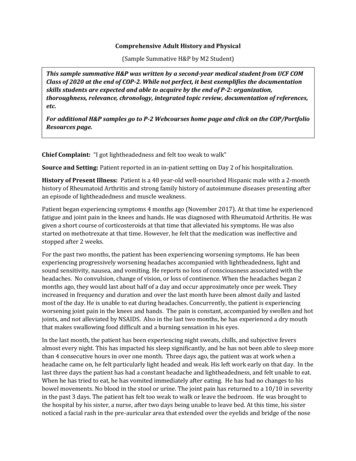
2STEEL PIPEAccording to the general procedure of the times, a 55,000-psi (379.2 MPa) tensilestrength steel was used. With a 4-to-1 safety factor, this resulted in a 13,750-psi(94.8 MPa) design stress. Lock-Bar pipe had notable advantages over riveted pipe: ithad only one or two straight seams and no round seams. The straight seams were considered 100-percent efficient as compared to the 45-percent to 70-percent efficiency forriveted seams. Manufactured in sizes from 20 in. (500 mm) through 74 in. (1,850 mm),from plate ranging in thickness from 3 16 in. (4.8 mm) to l 2 in. (12.7 mm), Lock-Barplayed an increasingly greater role in the market until the advent of automatic electric welding in the mid 1920s.By the early 1930s, both the riveting and Lock-Bar methods gradually werereplaced by welding. Pipe produced using automatic electric-fusion welding wasadvantageous because fewer pieces were used, fewer operations were performed, andbecause of faster production, smaller seam protrusion, and 100-percent welded-seamefficiency. The fabricators of fusion-welded pipe followed similar initial productionsequences as for Lock-Bar. Through the 1930s and into the 1940s, 30-ft (9.1-m) plateswere used. By the 1950s, some firms had obtained 40-ft (12.2-m) rolls, and a fewformed 40-ft (12.2-m) lengths in presses.In the 1930s, a new approach was used to design stresses. Prior to that time, it hadbeen common practice to work with a safety factor of 4-to-1 based on the tensilestrength. As welded pipe became predominant, using 50 percent of the material yieldstress became widely accepted.Helically formed and welded pipe was developed in the early 1930s and was usedextensively in diameters from 4 in. (100 mm) through 36 in. (875 mm). Welding wasperformed using the electric fusion method. After World War II, German machineswere imported, and subsequently, domestic ones were developed that could spirallyform and weld through diameters of 144 in. (3,600 mm).USESSteel water pipe meeting the requirements of appropriate AWWA standards has beenfound satisfactory for many applications, some of which follow:AqueductsSupply linesTransmission mainsDistribution mainsPenstocksTreatment-plant piping (Figure 1-1)Self-supporting spansForce mainsCirculating-water linesUnderwater crossings, intakes, and outfallsThe installation of pipe in this plant was simplified using the specially designed fittings and lightweight pipe.Figure 1-1Steel pipe in filtration plant galleryAWWA Manual M11Copyright 2004 American Water Works Association. All Rights Reserved.
HISTORY, USES, AND PHYSICAL CHARACTERISTICS3General data on some of the notable steel pipelines have been published (Cates1971, Hinds 1954). Data on numerous others have appeared in the Journal AWWAand other periodicals, as well as in many textbooks and engineering handbooks.CHEMISTRY, CASTING, AND HEAT TREATMENTGeneralThe properties of steels are governed by their chemical composition, by the processes used to transform the base metal into the shape, and by their heat treatment.The effects of these parameters on the properties of steels are discussed in the following sections.Chemical CompositionConstructional steels are a mixture of iron and carbon with varying amounts of otherelements—primarily manganese, phosphorus, sulfur, and silicon. These and other elements are unavoidably present or intentionally added in various combinations toachieve specific characteristics and properties of the finished steel products. Theeffects of the commonly used chemical elements on the properties of hot-rolled andheat-treated carbon and alloy steels are presented in Table 1-1. The effects of carbon,manganese, sulfur, silicon, and aluminum will be discussed.Carbon is the principal hardening element in steel because each additional increment increases the hardness and tensile strength of the steel. Carbon has a moderatetendency to segregate, and increased amounts of carbon cause a decrease in durability, toughness, and weldability.Manganese increases the hardness and strength of steels but to a lesser degreethan carbon. Manganese combines with sulfur to form manganese sulfides, thereforedecreasing the harmful effects of sulfur.Table 1-1Effects of alloying elementsAluminum (Al) Used to deoxidize or “kill” molten steelBoron (B) Small amounts (0.0005 %) increases hardenabilityin quenched and tempered steels Used only in aluminum killed steels Most effective at low carbon levelsCarbon (C) Principal hardening element in steel Increases strength and hardness Decreases ductility, toughness, and weldability Moderate tendency to segregateChromium (Cr) Increases strength Increases atmospheric corrosion resistanceCopper (Cu) Primary contributor to atmospheric corrosionresistanceManganese (Mn) Increases strength Controls harmful effects of sulfurAWWA Manual M11Nickel (Ni) Increases strength and toughnessNitrogen (N) Increases strength and hardnessPhosphorus (P) Increases strength and hardness Decreases ductility and toughness Considered an impurity, but sometimes addedfor atmospheric corrosion resistanceSilicon (Si) Used to deoxidize or “kill” molten steel Decreases durability and toughnessSulfur (S) Considered undesirable except for machinability Decreases ductility, toughness, and weldability Adversely affects surface quality Strong tendency to segregateVanadium (V) and Columbium (Nb) Small additions increase strengthCopyright 2004 American Water Works Association. All Rights Reserved.
4STEEL PIPESulfur is generally considered an undesirable element except when machinability isan important consideration. Sulfur adversely affects surface quality, has a strong tendency to segregate, and decreases ductility, toughness, and weldability.Silicon and aluminum are the principal deoxidizers used in the manufacture of carbon and alloy steels. Aluminum is also used to control and refine grain size.CastingThe traditional steel-making process is performed by pouring (teeming) molten steelinto a series of molds to form castings known as ingots. The ingots are removed fromthe molds, reheated, then rolled into products with square or rectangular cross sections. This hot-rolling operation elongates the ingots and produces semifinished products known as blooms, slabs, or billets. All ingots exhibit some degree of nonuniformityof chemical composition known as segregation. This is an inherent characteristic of thecooling and solidification of the molten steel in the mold.The initial liquid steel contacting the relatively cold walls and bottom of the moldsolidifies very rapidly, having the same chemical composition as the liquid steel entering the mold. However, as the rate of solidification decreases away from the moldsides, crystals of relatively pure iron solidify first. The first crystals to form containless carbon, manganese, phosphorus, sulfur, and other elements than the liquid steelfrom which they were formed. The remaining liquid is enriched by these elementsthat are continually being rejected by the advancing crystals. Consequently, the lastliquid to solidify, which is located around the axis in the top half of the ingot, containshigh levels of rejected elements and has a lower melting point than the poured liquidsteel. This segregation of the chemical elements is frequently expressed as a localdeparture from the average chemical composition. In general, the content of an element that has a tendency to segregate is greater than average at the center of the tophalf of an ingot and less than average at the bottom half of an ingot.Certain elements tend to segregate more than others. Sulfur segregates to the greatest extent. The following elements also segregate, but to a lesser degree, and in descending order are phosphorus, carbon, silicon, and manganese. The degree of segregation isinfluenced by the composition of the liquid steel, the liquid temperature, and the ingotsize. The most severely segregated areas of the ingot are removed by cropping, which isthe process of cutting and discarding sufficient material during rolling.Continuous casting is the direct casting of steel from the ladle into slabs. This steelmaking process bypasses the operations between molten steel and the semifinishedproduct that are inherent in making steel products from ingots. During continuouscasting, molten steel is poured at a regular rate into the top of an oscillating watercooled mold with a cross-sectional size corresponding to the desired slab. As the molten metal begins to solidify along the mold walls, it forms a shell that permits thegradual withdrawal of the strand product from the bottom of the mold into a waterspray chamber where solidification is completed. The solidified strand is cut to lengthand then reheated and rolled into finished projects, as in the conventional ingot process. Continuous casting produces a smaller size and higher cooling rate for thestrand, resulting in less segregation and greater uniformity in composition and properties for steel products than for ingot products.Killed and Semikilled SteelsThe primary reaction involved in most steel-making processes is the combination of carbon and oxygen to form carbon monoxide gas. The solubility of this and other gases dissolved in the steel decreases as the molten metal cools to the solidification temperatureAWWA Manual M11Copyright 2004 American Water Works Association. All Rights Reserved.
HISTORY, USES, AND PHYSICAL CHARACTERISTICS5range. Excess gases are expelled from the metal and, unless controlled, continue toevolve during solidification. The oxygen available for the reaction can be eliminatedand the gaseous evolution inhibited by deoxidizing the molten steel using additions ofsilicon or aluminum or both. Steels that are strongly deoxidized do not evolve anygases and are called killed steels because they lie quietly in the mold. Increasing gasevolution results in semikilled, capped, or rimmed steels.In general, killed steels are less segregated and contain negligible porosity when compared to semikilled steels. Consequently, killed-steel products usually exhibit a higherdegree of uniformity in composition and properties than semikilled steel products.Heat Treatment for SteelsSteels respond to a variety of heat treatments that produce desirable characteristics.These heat treatments can be divided into slow cooling treatments and rapid coolingtreatments. Slow cooling treatments, such as annealing, normalizing, and stressrelieving, decrease hardness and promote uniformity of structure. Rapid cooling treatments, such as quenching and tempering, increase strength, hardness, and toughness.Heat treatments of base metal are generally mill options or ASTM requirements.Annealing. Annealing consists of heating the steel to a given temperature followed by slow cooling. The temperature, the rate of heating and cooling, and theamount of time the metal is held at temperature depends on the composition, shape,and size of the steel product being treated and the desired properties. Usually steelsare annealed to remove stresses, induce softness, increase ductility and toughness,produce a given microstructure, increase uniformity of microstructure, improvemachinability, or to facilitate cold forming.Normalizing. Normalizing consists of heating the steel to between 1,650 F and1,700 F (899 C and 927 C) followed by slow cooling in air. This heat treatment iscommonly used to refine the grain size, improve uniformity of microstructure, andimprove ductility and fracture toughness.Stress relieving. Stress relieving of carbon steels consists of heating the steel tobetween 1,000 F to 1,200 F (538 C to 649 C) and holding for the appropriate amountof time to equalize the temperature throughout the piece followed by slow cooling. Thestress-relieving temperature for quenched and tempered steels must be maintainedbelow the tempering temperature for the product. Stress relieving is used to relieveinternal stresses induced by welding, normalizing cold working, cutting, quenching,and machining. It is not intended to alter the microst
AWWA MANUAL M11 Chapter 1 History, Uses, and Physical Characteristics of Steel Pipe HISTORY _ Steel pipe has been used for water lines in the United States since the early 1850s (Elliot 1922). The pipe was first manufactured by rolling steel sheets or plates into shape and riveting the seams. This method of fabrication continued with improve-ments into the 1930s. Pipe wall thicknesses .File Size: 513KBPage Count: 19