Transcription
Installation Manual20002158, Rev DCDecember 2010Micro Motion ELITE Coriolis Flow and DensitySensors
Safety and approval informationThis Micro Motion product complies with all applicable European directives when properly installed in accordance with the instructions in this manual.Refer to the EC declaration of conformity for directives that apply to this product. The EC declaration of conformity, with all applicable Europeandirectives, and the complete ATEX Installation Drawings and Instructions are available on the internet at www.micromotion.com/atex or through yourlocal Micro Motion support center.Information affixed to equipment that complies with the Pressure Equipment Directive can be found on the internet at www.micromotion.com/documentation.For hazardous installations in Europe, refer to standard EN 60079-14 if national standards do not apply.Other informationFull product specifications can be found in the product data sheet. Troubleshooting information can be found in the transmitter configuration manual.Product data sheets and manuals are available from the Micro Motion web site at www.micromotion.com/documentation.Return policyMicro Motion procedures must be followed when returning equipment. These procedures ensure legal compliance with government transportationagencies and help provide a safe working environment for Micro Motion employees. Failure to follow Micro Motion procedures will result in yourequipment being refused delivery.Information on return procedures and forms is available on our web support system at www.micromotion.com, or by phoning the Micro MotionCustomer Service department.Micro Motion customer serviceLocationTelephone numberU.S.A.800-522-MASS (800-522-6277) (toll free)Canada and Latin America 1 303-527-5200 (U.S.A.)AsiaEuropeJapan3 5769-6803All other locations 65 6777-8211 (Singapore)U.K.0870 240 1978 (toll-free)All other locations 31 (0) 318 495 555 (The Netherlands)Customers outside the U.S.A. can also send an email to flow.support@emerson.com.
ContentsContentsChapter 1Planning .11.11.21.31.4Chapter 2Mounting .72.12.22.32.42.52.6Chapter 3Installation checklist .1Best practices .2Environmental limits .3Recommendations for hygienic and self-draining applications .5Mount the sensor .7Mount electronics of high-temperature sensors .8Mount a CMF010 sensor to a wall or pole .11Mount a CMFS010 or CMFS015 sensor in a bracket .12Secure wafer-style process connections .13Attach extended electronics .15Wiring .173.13.23.3Options for wiring .17Connect 4-wire cable .17Connect 9-wire cable .20Chapter 4Grounding .22Chapter 5Supplementary information .235.15.25.3Installation ManualPurge the sensor case .23About rupture disks .25Pressure ratings for EN-1092 flanges .25i
ContentsiiMicro Motion ELITE
Planning1PlanningTopics covered in this chapter: 1.1Installation checklistBest practicesEnvironmental limitsRecommendations for hygienic and self-draining applicationsInstallation checklist Make sure that the hazardous area specified on the sensor approval tag is suitablefor the environment in which the sensor is installed. Verify that the local ambient and process temperatures are within the limits of thesensor. See Environmental limits. If your sensor has an integral transmitter, no wiring is required between the sensorand transmitter. Follow the wiring instructions in the transmitter installation manualfor signal and power wiring. If your transmitter has remote-mounted electronics, follow the instructions in thismanual for wiring between the sensor and the transmitter, and then follow theinstructions in the transmitter installation manual for power and signal wiring. For the wiring between the sensor and the transmitter, consider maximum cablelengths (see Table 1-1 and Table 1-2). The maximum distance between the sensorand transmitter depends on the cable type. For all types of wiring, Micro Motionrecommends using Micro Motion cable.Table 1-1: Maximum lengths for Micro Motion cableCable typeTo transmitterMaximum lengthMicro Motion 9-wire9739 MVD transmitter1000 ft (300 m)All other MVD transmitters60 ft (20 m)All 4-wire MVD transmitters1000 ft (300 m)Micro Motion 4-wireTable 1-2: Maximum lengths for user-supplied 4-wire cableWire functionWire sizeMaximum lengthPower (VDC)22 AWG (0,35 mm2)300 ft (90 m)20 AWG (0,5 mm2)500 ft (150 m)18 AWG (0,8 mm2)1000 ft (300 m)22 AWG (0,35 mm2) or larger1000 ft (300 m)Signal (RS-485)Installation Manual1
Planning For best performance, follow Micro Motion recommendations for sensor orientation(see Table 1-3). The sensor will work in any orientation as long as the flow tubesremain full of process fluid.Table 1-3: Recommended sensor orientationLiquidsGasesSlurries 1.2Install the sensor so that the flow direction arrow on the sensor matches the actualforward flow of the process.Best practicesThe following information can help you get the most from your sensor.2 There are no pipe run requirements for Micro Motion sensors. Straight runs of pipeupstream or downstream are unnecessary. If the sensor is installed in a vertical pipeline, liquids and slurries should flow upwardthrough the sensor. Gases may flow upward or downward. Keep the sensor tubes full of process fluid. For halting flow through the sensor with a single valve, install the valve downstreamfrom the sensor. Minimize bending and torsional stress on the meter. Do not use the meter to alignmisaligned piping. The sensor does not require external supports. The flanges will support the sensor inany orientation. (Some sensor models installed in very small, flexible pipeline haveoptional installation instructions that allow for external supports.) When transporting or lifting large sensors, it may be useful to identify the sensor'scenter of gravity (see Figure 1-1). Refer to the Product Data Sheet for exact centerof-gravity and weight specifications.Micro Motion ELITE
PlanningFigure 1-1: Center of gravity for large metersAA. Approximate center of gravity1.3Environmental limitsThe ambient and process temperature limits of the sensor are shown in the followingfigures.Installation Manual For all ELITE sensor models except high-temperature and extreme-hightemperature models, see Figure 1-2. For high-temperature and extreme-high-temperature ELITE sensors, see Figure 1-3.3
PlanningFigure 1-2: Environmental limits for typical sensorsGray area Mount transmitter remotely (use junction box)Ambient temperature of core processor ortransmitter in F ( C)176 (80)140(60)140 (60)113 (45)104 (40)68 (20)32 (0)–4 (–20)–40 (–40)–76 (60)–112 (–80)–148 –76(–60)32(0)140(60)248(120)356464(180) 400 (240)(204)Maximum process temperature in F ( C)Notes 4When ambient temperature is below –40 F (–40 C), a core processor or transmitter must beheated to bring its local ambient temperature to between –40 F (–40 C) and 140 F ( 60 C).Long-term storage of electronics at ambient temperatures below –40 F (–40 C) is notrecommended.Temperature limits may be further restricted by hazardous area approvals. Refer to the hazardousarea approvals documentation shipped with the sensor or available from the Micro Motion web site(www.micromotion.com).The extended-electronics option allows the sensor case to be insulated without covering thetransmitter, core processor, or junction box, but does not affect temperature ratings.For the purposes of selecting electronics options, this graph should be used only as a general guide.If your process conditions are close to the gray areas, it may be inappropriate to use electronicsoptions other than a junction box. Consult with your Micro Motion representative.Micro Motion ELITE
PlanningFigure 1-3: Environmental limits for high-temperature sensorsGray area Mount transmitter remotely (use junction box)Ambient temperature of core processor ortransmitter in F ( C)176 (80)140 (60)104 (40)High-temp. models68 (20)32 (0)Extreme high-temp. models–4 (–20)–40 (–40)–76 (60)–112 (–80)–148 2(200)482(250)572(300)662(350)752842(400) 800 (450)(427)Maximum process temperature in F ( C)Notes 1.4When ambient temperature is below –40 F (–40 C), a core processor or Model 2400S transmittermust be heated to bring its local ambient temperature to between –40 F (–40 C) and 140 F( 60 C). Long-term storage of electronics at ambient temperatures below –40 F (–40 C) is notrecommended.Temperature limits may be further restricted by hazardous area approvals. Refer to the hazardousarea approvals documentation shipped with the sensor or available from the Micro Motion web site(www.micromotion.com).Recommendations for hygienic and selfdraining applicationsCMFS sensors are certified EHEDG TYPE EL CLASS I for hygienic applications when installedvertically with the process fitting and gasket combinations listed in the Position Paper ofthe EHEDG Test Methods Subgroup (available at www.ehedg.org). Other processconnections/gasket combinations may be used provided they have been evaluated andsuccessfully tested for in-place cleanability according to the latest edition of EHEDGDocument 2. Refer to the ELITE Product Data Sheet for further information about fittingoptions.For optimal cleanability and drainability:Installation Manual5
Planning If possible, install the sensor in a vertical pipeline with the process fluid flowingupward through the sensor.See Figure 1-4. If the sensor must be installed in a horizontal pipeline, drainage is accomplished byair purge evacuation of the pipeline circuit. For clean-in-place (CIP) applications, Micro Motion recommends using thegenerally-accepted flow velocity of at least 1.5 m/s for cleaning the sensor. The gap between the electronics housing and sensor body should be inspectedperiodically. Manually clean this gap when necessary.Figure 1-4: Installation for self-draining applicationsABCA.B.C.6Process pipelineDirection of normal process flowDirection of drainageMicro Motion ELITE
Mounting2MountingTopics covered in this chapter: 2.1Mount the sensorMount electronics of high-temperature sensorsMount a CMF010 sensor to a wall or poleMount a CMFS010 or CMFS015 sensor in a bracketSecure wafer-style process connectionsAttach extended electronicsMount the sensorUse your common practices to minimize torque and bending load on process connections.TipTo reduce the risk of condensation or excessive moisture, the conduit opening should not pointupward (if possible). The conduit opening of the junction box or core processor can be rotated freelyto facilitate wiring.ProcedureMount the sensor in the pipeline (see Figure 2-1).Installation Manual7
MountingFigure 2-1: Mounting the sensorNotes Do not use the sensor to support the piping. The sensor does not require external supports. The flanges will support the sensor in any orientation.(Some sensor models installed in very small, flexible pipeline have optional installation instructionsthat allow for external supports.)CAUTION!Do not lift the sensor by the electronics or purge connections. Lifting the sensor by theelectronics or purge connections can damage the device.2.2Mount electronics of high-temperature sensorsThe electronics of high-temperature sensors are attached to the end of a 32" (812 mm)pre-installed flexible conduit. The electronics must be separately mounted on a wall orinstrument pole.See Figure 2-2 for an illustration of high-temperature sensor electronics.8Micro Motion ELITE
MountingFigure 2-2: Components of a high-temperature sensorADBCA.B.C.D.ElectronicsMounting bracketFlexible conduit (minimum bend radius 6" [152 mm])SensorWith some large meter sizes, the meter may ship with the electronics attached to thesensor case. See Figure 2-3. The meter cannot be operated in this configuration. Detachthe electronics bracket from the sensor case and then proceed to mount the electronics toa wall or instrument pole as described below.ImportantDo not operate the meter while the electronics are attached to the sensor case.Installation Manual9
MountingFigure 2-3: Removing electronics from the sensor caseAA.Detach electronics from sensor case and mount to a wall or instrument poleProcedure For wall mounting, use four 5/16" or four M8 bolts to secure the mounting bracket.See Figure 2-4.Figure 2-4: Wall-mount componentsBACA. Wall or flat surfaceB. Electronics (enhanced core processor shown)C. Flexible conduit 10For mounting to an instrument pole, use a 2-inch U-bolt pipe kit to secure themounting bracket. See Figure 2-5.Micro Motion ELITE
MountingFigure 2-5: Pole-mount componentsABCA. Instrument poleB. Electronics (enhanced core processor shown)C. Flexible conduit2.3Mount a CMF010 sensor to a wall or poleThe CMF010 sensor has an optional mounting configuration for use with small or flexiblepipeline. If the pipeline adequately supports the sensor, this procedure can be skipped.1.Installation ManualLocate the optional mounting holes. For sensors with a junction box, the junctionbox must be rotated to the side to expose the mounting holes. See Figure 2-6.11
MountingFigure 2-6: Optional mounting for CMF010 sensorsABCA. Two user-supplied 5/16" (M8) boltsB. Junction box or core processor (junction box shown)C. Mounting surface2.42.If necessary, install rigid standoffs between the sensor and the mounting surface.3.Using two user-supplied 5/16" (M8) bolts (minimum length 2 1/4" [58 mm]), securethe sensor case to the mounting surface.Mount a CMFS010 or CMFS015 sensor in abracketThe CMFS010 and CMFS015 sensors have an optional mounting bracket for use with smallor flexible pipeline. If the pipeline adequately supports the sensor, this procedure can beskipped.121.Secure the mounting bracket to a wall or other flat surface with four user-supplied5/16" (8 mm) bolts. See Figure 2-7.2.Place the sensor into the bracket.3.Secure the sensor in the bracket with the supplied 5/16" (M8) U-bolts.Micro Motion ELITE
MountingFigure 2-7: Mounting bracket for CMFS010 and CMFS015ABCA.B.C.2.5Mounting bracketMounting holesSupplied U-boltsSecure wafer-style process connectionsA wafer-style connection lets you clamp the sensor into the pipeline. A wafer installationkit is shipped with a wafer-style sensor.1.Make sure that the bolts provided are rated for your process connection.2.Slip the sensor alignment rings over each end of the sensor wafer, then insert thesensor between the process connections in the pipeline. See Figure 2-8.TipMicro Motion recommends installing gaskets (user-supplied).Installation Manual13
MountingFigure 2-8: Wafer-style connection componentsABCDEA.B.C.D.E.Sensor waferFlange boltAlignment ringFlange nutGasket (user-supplied)3.Insert the flange bolts through both process connections, and thread the flange nutsonto the bolts.4.With your fingers, tighten the flange nuts.5.Rotate the sensor alignment rings in the direction that pushes the bolts outward.See Figure 2-9.TipRotate both sensor aligment rings until the assembly is centered and tight.Figure 2-9: Alignment ring usageABCA. Direction to rotate the alignment ringB. Direction the flange bolts are pushedC. Flange bolt14Micro Motion ELITE
Mounting6.2.6With a wrench, tighten the nuts in an alternating order.Attach extended electronicsIf you ordered a sensor with extended electronics, you will need to install the extenderonto the sensor case.NoteExtended core processors are matched at the factory to specific sensors. Keep each core processortogether with the sensor with which it was shipped.CAUTION!Keep the extender and feedthrough clean and dry. Moisture or debris in the extender orfeedthrough can damage electronics and result in measurement error or flowmeter failure.Procedure1.Installation ManualRemove and recycle the plastic cap from the feedthrough on the sensor. SeeFigure 2-10.15
MountingFigure 2-10: Feedthrough and extender componentsABCEGDFHA.B.C.D.E.F.G.H.16Transmitter or core processorExtenderPlastic plugPlastic capO-ringClamping ringClamping screwFeedthrough2.Loosen the clamping screw and remove the clamping ring. Leave the O-ring in placeon the feedthrough.3.Remove and recycle the plastic plug from the extender.4.Fit the extender onto the feedthrough by carefully aligning the notches on thebottom of the extender with the notches on the feedthrough.5.Close the clamping ring and tighten the clamping screw to 13–18 in-lbs.(1,5–2 N-m).Micro Motion ELITE
Wiring3WiringTopics covered in this chapter: 3.1Options for wiringConnect 4-wire cableConnect 9-wire cableOptions for wiringThe wiring procedure you follow depends on which electronics option you have.See Table 3-1 for the wiring options for each sensor electronics option.Table 3-1: Wiring procedures by electronics optionElectronics optionWiring procedureIntegral transmitterNo wiring required between sensor and transmitter. See the transmitterinstallation manual for wiring the power and signal cable to the transmitter. MVD Direct ConnectNo transmitter to wire. See the MVD Direct Connect manual for wiring thepower and signal cable between the sensor and the direct host.Core processorSee Connect 4-wire cable.Junction boxSee Connect 9-wire cable.CAUTION!Make sure the hazardous area specified on the sensor approval tag is suitable for theenvironment in which the sensor will be installed. Failure to comply with the requirements forintrinsic safety in a hazardous area could result in an explosion.CAUTION!Fully close and tighten all housing covers and conduit openings. Improperly sealed housingscan expose electronics to moisture, which can cause measurement error or flowmeter failure.Inspect and grease all gaskets and O-rings.3.2Installation ManualConnect 4-wire cable17
WiringStep 1: Cable preparationRemove the core processorcoverCable glandsCable layoutMetal conduitGland supplierMicro Motioncable glandUser-suppliedcable glandRun conduit tosensorPass the wires through the gland nut and clamping insert.Gland nutPass the wiresthrough the glandClampinginsertLay cable in conduitGo to Step 3NPTM20Gland type1. Strip 4-1/2 inch (115 mm) of cable jacket.2. Remove the clear wrap and filler material.3. Strip all but 3/4 inch (19 mm) of shielding.1. Strip 4-1/4 inch (108 mm) of cable jacket.2. Remove the clear wrap and filler material.3. Strip all but 1/2 inch (12 mm) of shielding.Wrap the drain wires twice around the shield and cut offthe excess drain wires.Drain wireswrapped aroundshieldGo to Step 218Micro Motion ELITE
WiringStep 2: Shield terminationFrom Step 1Micro Motioncable glandBraided(armored cable)Cable shieldtypeUser-suppliedcable glandGland supplierFoil(shielded cable)NPTGland typeApply the Heat Shrink1. Slide the shielded heat shrink over the drain wires. Ensure that thewires are completely covered.2. Apply heat (250 F or 120 C) to shrink the tubing. Do not burn thecable.3. Position the clamping insert so the interior end is flush with the braidof the heat shrink.M20Trim 7 mm from the shieldedheat shrinkTrimShielded heatshrinkAfter heat appliedTerminate the shieldand drain wires in theglandAssemble the Gland1. Fold the shield or braid back over the clamping insert and 1/8 inch(3 mm) past the O-ring.2. Install the gland body into the conduit opening on the core processor housing.3. Insert the wires through gland body and tighten the gland nut onto the gland body.Shield folded backAssemble the glandaccording to vendorinstructionsGland bodyGo to Step 3Installation Manual19
WiringStep 3: Terminal connectionsFrom Step 1 or 2Standardcore processorCore processortypeConnect the wires to the core processor terminals:Red wire Terminal 1 (Power supply )Black wire Terminal 2 (Power supply –)White wire Terminal 3 (RS-485/A)Green wire Terminal 4 (RS-485/B)Reinstall and tighten the core processor coverEnhancedcore processorConnect the wires to the core processor terminals:Red wire Terminal 1 (Power supply )Black wire Terminal 2 (Power supply –)White wire Terminal 3 (RS-485/A)Green wire Terminal 4 (RS-485/B)1. Reinstall the core processor cover.2. Torque cover screws to: 10–13 in-lbs (1,13–1,47 N-m) for aluminum housing Minimum 19 in-lbs (2,1 N-m) for stainless steelhousingConnect the wires to the transmitterterminals(see the transmitter manual)3.320Connect 9-wire cable1.Prepare and install the cable according to the instructions in the Micro Motion 9Wire Flowmeter Cable Preparation and Installation Guide.2.Insert the stripped ends of the individual wires into the terminal blocks. Ensure thatno bare wires remain exposed.Micro Motion ELITE
WiringInstallation Manual3.Match the wires color for color. For wiring at the transmitter or remote coreprocessor, refer to the transmitter documentation.4.Tighten the screws to hold the wires in place.5.Ensure integrity of gaskets, then tightly close and seal the junction box cover and allhousing covers on the transmitter or core processor.6.Refer to the transmitter installation manual for signal and power wiring instructions.21
Grounding4GroundingThe sensor must be grounded according to the standards that are applicable at the site.The customer is responsible for knowing and complying with all applicable standards.PrerequisitesMicro Motion suggests the following guides for grounding practices: In Europe, IEC 79-14 is applicable to most installations, in particular Sections12.2.2.3 and 12.2.2.4. In the U.S.A. and Canada, ISA 12.06.01 Part 1 provides examples with associatedapplications and requirements.If no external standards are applicable, follow these guidelines to ground the sensor: Use copper wire, 14 AWG (2,0 mm2) or larger wire size. Keep all ground leads as short as possible, less than 1 Ω impedance. Connect ground leads directly to earth, or follow plant standards.CAUTION!Ground the flowmeter to earth, or follow ground network requirements for the facility.Improper grounding can cause measurement error.ProcedureCheck the joints in the pipeline.-If the joints in the pipeline are ground-bonded, the sensor is automatically groundedand no further action is necessary (unless required by local code).-If the joints in the pipeline are not grounded, connect a ground wire to the groundingscrew located on the sensor electronics.TipThe sensor electronics may be a transmitter, core processor, or junction box. The groundingscrew may be internal or external.22Micro Motion ELITE
Supplementary information5Supplementary informationTopics covered in this chapter: 5.1Purge the sensor caseAbout rupture disksPressure ratings for EN-1092 flangesPurge the sensor caseIf the sensor has purge fittings, they should remain sealed at all times. After a purge plughas been removed, the sensor case should be purged with argon or nitrogen and resealed.Purging the case protects internal components. The sensor is purged of all oxygen andsealed at the factory. If the purge plugs are never removed, it is not necessary to purge orre-seal the sensor. For more information, contact Micro Motion Customer Service.If a purge plug is removed from the sensor case, it will be necessary to repurge the case.CAUTION!Take all necessary precautions when removing purge plugs. Removing a purge plugcompromises the secondary containment of the sensor and could expose the user to processfluid.CAUTION!Improper pressurization of the sensor case could result in personal injury. Removing a purgeplug will require the sensor case to be repurged with a dry inert gas. Follow all instructionsprovided in the case purging procedure.PrerequisitesMake sure the following are available before beginning the purge procedure: Teflon tape Argon or nitrogen gas sufficient to purge the sensor caseProcedureInstallation Manual1.Shut down the process, or set control devices for manual operation. Beforeperforming the case purging procedure, shut down the process or set the controldevices for manual operation. Performing the purge procedure while the flowmeteris operating could affect measurement accuracy, resulting in inaccurate flow signals.2.Remove both purge plugs from the sensor case. If purge lines are being used, openthe valve in the purge lines.3.Prepare the purge plugs for reinstallation by wrapping them with 3–5 turns of Teflontape.23
Supplementary information4.Connect the supply of nitrogen or argon gas to the inlet purge connection or openinlet purge line. Leave the outlet connection open. Exercise caution to avoid introducing dirt, moisture, rust, or other contaminantsinto the sensor case. If the purge gas is heavier than air (such as argon), locate the inlet lower than theoutlet, so that the purge gas will displace air from bottom to top. If the purge gas is lighter than air (such as nitrogen), locate the inlet higher thanthe outlet, so that the purge gas will displace air from top to bottom.5.Make sure that there is a tight seal between the inlet connection and sensor case, sothat air cannot be drawn by suction into the case or purge line during the purgingprocess.6.Run purge gas through the sensor.The purge time is the amount of time required for full exchange of atmosphere toinert gas. The larger the line size, the greater amount of time is required to purgethe case. See Table 5-1. If purge lines are being used, increase the purge time to fillthe additional volume of the purge line.NoteKeep the purge gas pressure below 30 psig (2 bar).Table 5-1: Purge time7.Sensor modelPurge rate, in ft3/hr (l/h)Time, in minutesCMF01020 (566)1CMF02520 (566)1CMF05020 (566)2CMF10020 (566)5CMF20020 (566)12CMF30020 (566)30CMF40020 (566)55CMFHC220 (566)100CMFHC320 (566)170CMFHC420 (566)268At the appropriate time, shut off the gas supply, then immediately seal the purgeoutlet and inlet connections with the purge plugs.NoteAvoid pressurizing the sensor case. If pressure inside the case elevates above atmosphericpressure during operation, the flowmeter density calibration will be inaccurate.24Micro Motion ELITE
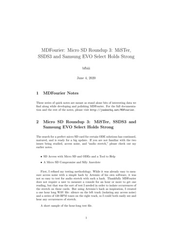
Supplementary information8.5.2Make sure that the purge fitting seals are tight so that air cannot be drawn bysuction into the sensor case.About rupture disksRupture disks are meant to vent process fluid from the sensor case in the event of a flowtube rupture. Some users connect a pipeline to the rupture disk to help contain escapingprocess fluid. For more information about rupture disks, contact Micro Motion CustomerService.If the sensor has rupture disks, they are installed in the sensor purge fitting openings. Therupture disks should remain installed at all times. If you remove a rupture disk from thesensor case, it will be necessary to re-purge the case.CAUTION!Stay clear of the rupture disk pressure relief area. High-pressure fluid escaping from the sensorcan cause severe injury or death.5.3Pressure ratings for EN-1092 flangesSee Figure 5-1 for pressure ratings for EN-1092 flanges.Installation Manual25
Supplementary informationFigure 5-1: Pressure ratings for EN-1092 427 CA.B.C.D.26EN 1092-1 PN40, Form B1; 11 weld neck; 304 stainless steelEN 1092-1 PN40, Form B1 & D; 11 weld neck; 316 stainless steelEN 1092-1 PN100, Form B2 & D; 11 weld neck; 316 stainless steelEN 1092-1 PN40, Form B1; 32/02 lap joint; alloy C-22 collar/304 stainless steel flangeMicro Motion ELITE
*20002158*20002158Rev DC2010Micro Motion Inc. USAWorldwide Headquarters7070 Winchester CircleBoulder, Colorado 80301T 1 303-527-5200T 1 800-522-6277F 1 303-530-8459www.micromotion.comMicro Motion EuropeEmerson Process ManagementNeonstraat 16718 WX EdeThe NetherlandsT 31 (0) 318 495 555F 31 (0) 318 495 556www.micromotion.nlMicro Motion AsiaEmerson Process Management1 Pandan CrescentSingapore 128461Republic of SingaporeT 65 6777-8211F 65 6770-8003Micro Motion United KingdomEmerson Process Management
agencies and help provide a safe working environment for Micro Motion employees. Failure to follow Micro Motion procedures will result in your equipment being refused delivery. Information on return procedures and forms is available on our web support system at www.micromotion.com, or by phoning the Micro Motion Customer Service department.