Transcription
Wormhole Routing Techniques for Directly ConnectedMulticomputer SystemsPRASANT MOHAPATRAIowa State University, Department of Electrical and Computer Engineering, 201 Coover Hall, IowaState University, Ames, IA 50011; email: prasant@iastate.edu.&Wormhole routing has emerged as the most widely used switching technique inmassively parallel computers. We present a detailed survey of various techniquesfor enhancing the performance and reliability of wormhole-routing schemes indirectly connected networks. We start with an overview of the direct networktopologies and a comparison of various switching techniques. Next, thecharacteristics of the wormhole routing mechanism are described in detail alongwith the theory behind deadlock-free routing. The performance of routingalgorithms depends on the selection of the path between the source and thedestination, the network traffic, and the router design. The routing algorithms areimplemented in the router chips. We outline the router characteristics and describethe functionality of various elements of the router. Depending on the usage ofpaths between the source and the destination, routing algorithms are classified asdeterministic, fully adaptive, and partially adaptive. We discuss severalrepresentative algorithms for all these categories. The algorithms within eachcategory vary in terms of resource requirements and performance under varioustraffic conditions. The main difference among various adaptive routing schemes isthe technique used to avoid deadlocks. We also discuss a few algorithms based ondeadlock recovery techniques. Along with performance, fault tolerance is essentialfor message routing in multicomputers, and we thus discuss several fault-tolerantwormhole routing algorithms along with their fault-handling capabilities. Theserouting schemes enable a message to reach its destination even in the presence offaults in the network. The implementation details of wormhole routing algorithmsin contemporary commercial systems are also discussed. We conclude by itemizingseveral future directions and open issues.Categories and Subject Descriptors: B.4.3 [Input/Output and DataCommunications]: Interconnections (Subsystems)—topology; C.1.4 [ComputerSystems Organization]: Parallel Architectures; C.2.1 [ComputerCommunication Networks]: Network Architecture and Design; C.2.2[Computer-Communication Networks]: Network Protocols—routing protocols;C.2.6 [Computer-Communication Networks]: Internetworking—routersGeneral Terms: Algorithms, Design, Performance, ReliabilityAdditional Key Words and Phrases: Deadlock avoidance and recovery, directlyconnected multicomputers, fault-tolerance, network topology, router design,switching techniques, virtual channels, wormhole routing algorithmsThis research was supported in part by the National Science Foundation through grants MIP-9628801,CCR-9634547, and CDA-9617375.Permission to make digital / hard copy of part or all of this work for personal or classroom use is grantedwithout fee provided that the copies are not made or distributed for profit or commercial advantage, thecopyright notice, the title of the publication, and its date appear, and notice is given that copying is bypermission of the ACM, Inc. To copy otherwise, to republish, to post on servers, or to redistribute tolists, requires prior specific permission and / or a fee. 1998 ACM 0360-0300/98/0300–0374 05.00ACM Computing Surveys, Vol. 30, No. 3, September 1998
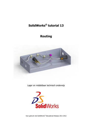
Computing SurveysCONTENTSINTRODUCTION2. DIRECT NETWORK TOPOLOGIES3. WORMHOLE SWITCHING3.1 Switching Techniques3.2 Virtual Channels3.3 Router Characteristics4. WORMHOLE ROUTING CHARACTERISTICS4.1 Classifications4.2 Deadlock-Free-Routing Theory4.3 Performance Evaluation5. DETERMINISTIC WORMHOLE ROUTING6. ADAPTIVE WORMHOLE ROUTING6.1 Fully Adaptive Algorithms6.2 Partially Adaptive Algorithms6.3 Deadlock Recovery in Fully Adaptive Algorithms7. FAULT-TOLERANT WORMHOLE ROUTING8. WORMHOLE ROUTINE IN COMMERCIAL SYSTEMS9. CONCLUSIONS AND OPEN ISSUES1. INTRODUCTIONLarge-scale parallel computers are potential candidates for providing veryhigh computational power. These systems are usually organized as an ensemble of nodes, each with its own processor, local memory, and othersupporting devices. The nodes are interconnected using a variety of topologiesthat can be classified into two broadcategories: direct and indirect. In directnetworks, each node has a point-topoint or direct connection to some of theother nodes, called neighboring nodes;examples of direct network topologiesinclude hypercube, mesh, and tree. Inindirect networks, the nodes are connected to other nodes or a shared memory through one or more switching elements. Examples of indirect networksinclude crossbar, bus, and multistageinterconnection networks.Direct networks have emerged as apopular architecture for massivelyparallel computers because of their scalability. The total communication bandwidth, memory bandwidth, and processing capability of the system increasewith the number of nodes. Examples of 375experimental and commercial systemsbased on the direct interconnection network include Intel’s iPSC, TouchstoneDelta [Intel 1990] and Paragon [Intel1991], Ncube-2/3 [NCUBE Company1990], Cray T3D [Kessler and Schwarzmeier 1993; Scott and Thorson 1994],MIT J-Machine [Noakes et al. 1993],and Stanford DASH [Lenoski et al.1992]. The nodes of a direct-networkbased multicomputer communicate bypassing messages through an interconnection network. Neighboring nodessend messages to one another directly,whereas nodes that are not connecteddirectly communicate with each otherby passing messages through intermediate nodes. Support hardware is essential to handle the transmission of messages between nodes. In most systems,a router is associated with each node tohandle communication-related tasks.Dedicated routers are also used to allowoverlapping of computation and communication within each node.Figure 1 shows the architecture of ageneric node consisting of a processor, alocal memory, a router, interconnects,and other functional units such as I/Odevices. The router has internal channels that connect it to the processor,local memory, or other functional units.The input internal channels are used toabsorb messages destined for the hostprocessor. The output internal channelsare used by the host processor to sendoutgoing messages to remote nodes.Some systems use multiple internalchannels to avoid communication bottlenecks between the local processor ormemory and the router. The multipleinternal channels can have either allport or k-port architecture. In the allport architecture, every external channel has a corresponding internalchannel, thus allowing the node to sendand receive on all external channels simultaneously. A k-port architecture hask internal channels, where k is lessthan the total number of external channels. The internal channels in a k-portrouter are multiplexed by the externalchannels, which are used for messagesACM Computing Surveys, Vol. 30, No. 3, September 1998
376 Prasant MohapatraFigure 1.Node architecture in a multicomputer system.in transit. Usually a crossbar switch isused in the router to connect the inputexternal channels to the output externalchannels. The control unit is responsible for flow control of the messages traversing the router.In direct-network-based multicomputers, a task is allocated to a group ofnodes that communicate for successfulexecution of the task. The speed of execution depends on the processor as wellas on the communication performance.The latency incurred by a message traversing from a source node to a destination node affects the overall performance of the multicomputer system.Because of the interprocessor interactions, the communication latency alsoaffects the granularity of parallelismthat can be exploited in the system.Thus it is essential to devise techniquesthat reduce the communication latencyincurred in direct networks.The communication latency is themost important performance metric indirect networks. It comprises start-uplatency, network latency, and the blocking time [Ni and McKinley 1993]. Thestart-up latency is the time required forthe system to handle the message at thesource and destination nodes and depends primarily on the design of theACM Computing Surveys, Vol. 30, No. 3, September 1998interface between the local processorsand routers. Network latency, definedas the time spent by a message in thenetwork, is computed as the time between the instant when the messagehead is injected into the network by thesource and the instant when the message tail is absorbed by the destinationnode. Both start-up and network latencies are fixed for a given network. Theblocking time of a message is the timespent waiting for a channel currentlybeing used by another message. Thusthe blocking time depends on the resource contentions that a message encounters in its path. Blocking time cannot be determined statically, as itdepends on the network traffic distribution and the path taken by a message.The communication latency of directnetworks depends on several factors including switching, routing, flow control,and topology. Several switching techniques have been proposed for directnetworks. Wormhole switching hasemerged as a popular technique and hasbeen used in both commercial and experimental systems. Wormhole switching can be employed in both direct andindirect networks. It is widely used incontemporary multicomputers becauseof its low latency and requirement of
Computing Surveyssmall buffers at the nodes. Theorieshave been developed for designing costeffective, efficient, deadlock-free, andlivelock-free wormhole routing algorithms. Based on these theories, severaldeterministic and adaptive routing algorithms have been proposed in the literature. In this article, we survey differenttechniques of wormhole routing alongwith the theory behind the design ofdeadlock-free algorithms. Complementary techniques for deadlock recoveryare also described. In addition, we review fault-tolerant wormhole routingschemes that can route messages in thepresence of faults. Details of wormholerouting schemes implemented in severalcommercial systems are also included.A preliminary survey on wormholerouting was given by Ni and McKinley[1993]. Since then, several advanceshave been made in wormhole-routednetworks. Furthermore, the present report discusses several issues not covered by the earlier survey report, suchas fault-tolerant routing, deadlock recovery techniques, router designs, andimplementation in commercial systems.Topics not discussed in this survey include collective communication androuting in indirect networks. Collectivecommunication could itself be the subject of a survey; indeed, one such workis by McKinley et al. [1995]. We focusprimarily on direct network topologiessuch as meshes and k-ary n-cubes because of their widespread adoption incommercial systems. However, we alsodiscuss the implementation of wormholerouting in some recent commercial systems (CM-5 and IBM SP1/SP2) that arebased on indirect networks.The rest of the survey is organized asfollows. The properties of direct networktopologies are outlined in Section 2. Section 3 discusses various switching techniques along with wormhole switching,which forms the basis of wormhole routing. Virtual channels, flow controlmechanisms, and router characteristicsare also described in this section. Theclassification of wormhole routing algorithms and deadlock-free routing theory 377are presented in Section 4. Section 5discusses various deterministic wormhole routing algorithms, followed by adiscussion of adaptive routing algorithms in Section 6 and of fault-tolerantrouting algorithms in Section 7. In Section 8, we discuss the implementation ofwormhole routing algorithms in commercial parallel computers, and giveconcluding remarks and a discussion ofopen issues in Section 9.2. DIRECT NETWORK TOPOLOGIESThe topology of a network defines howthe nodes are interconnected and is generally modeled as a graph in which thevertices represent the nodes and theedges denote the channels. Multidimensional meshes and k-ary n-cubes, thebasic topologies used in most parallelcomputers, are defined as follows [Niand McKinley 1993].Definition 1. An n-dimensional meshis an interconnection structure that hask 0 3 k 1 3 . . . 3 k n 2 1 nodes, where k idenotes the number of nodes in the ithdimension. Each node in the mesh isidentified by an n-coordinate vector (x 0 ,x 1 , . . . , x n 2 1 ), where 0 # x i # k i 2 1.Two nodes (x 0 , x 1 , . . . , x n 2 1 ) and (y 0 ,y 1 , . . . , y n 21 ) are connected if and onlyif there exists an i such that x i 5 y i 61, and x j 5 y j for all j Þ i. Thus thenumber of neighbors of a node rangesfrom n to 2n, depending on its locationin the mesh.Definition 2. A k-ary n-cube is defined as an interconnection structure ofn dimensions having k nodes in eachdimension. Each node in the k-ary ncube is identified by an n-coordinatevector (x 0 , x 1 , . . . , x n 2 1 ), where 0 #x i # k 2 1. Two nodes (x 0 , x 1 , . . . ,x n 2 1 ) and (y 0 , y 1 , . . . , y n 2 1 ) areconnected if and only if there exists an isuch that x i 5 (y i 6 1) mod k, and x j 5y j for all j Þ i. There are wraparoundchannels in the k-ary n-cubes (specifiedby the use of modulus in the definition),which are not present in n-dimensionalmeshes. If k 5 2, then every node has nACM Computing Surveys, Vol. 30, No. 3, September 1998
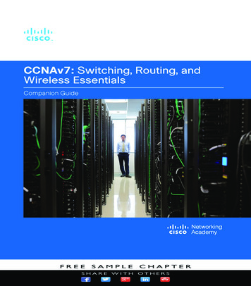
378 Prasant MohapatraFigure 2. Topology of a hypercube and a mesh: (a) three-dimensional hypercube; (b) two-dimensionalmesh (8 3 8).neighbors, one in each dimension. If k .2, then every node has 2n neighbors,two in each dimension.The hypercube and torus are twoother popular topologies for direct networks. Hypercubes are special cases ofan n-dimensional mesh in which k i 5 2,for all i, 0 # i # n 2 1; they can betermed 2-ary n-cubes. A k-ary n-cube iscalled a torus when n 5 2. Figure 2shows a three-dimensional (3-D) hypercube and a two-dimensional (2-D) mesh.A torus can be constructed by connecting the corresponding end nodes of the2-D mesh with wraparound connections.Several issues are associated with themesh, torus, and hypercube topologies.The mesh is an asymmetrical topologyin which the node degree depends on itslocation. Interprocessor communicationperformance depends on the location ofsource and destination. The channelsnear the center of the mesh experiencehigher traffic density than those on theperiphery. The torus and hypercube aresymmetrical topologies in which the degree of a node is the same irrespectiveof its location in the network. Thus,unlike the mesh, all the nodes in toriand hypercubes are identical in connectivity. The network diameter of a meshis greater than that of the torus, whichin turn has a greater diameter than thehypercube for the same number ofnodes.The bisection width of a network isACM Computing Surveys, Vol. 30, No. 3, September 1998defined as the number of channels thatmust be removed to partition the network into two equal subnetworks. Thebisection width has a significant effecton the interprocessor communicationperformance [Dally 1990]. The bisectionwidth (BW) of a 2 n 3 2 n 2-D mesh, 2 n 32 n 2-D torus, and a 2n-cube hypercubeare BW mesh 5 2 n , BW torus 5 2 n11 ,BW hypercube 5 2 2n21 , respectively. Thebisection density, which is the productof the bisection width and the channelwidth, can be used as a measure of thenetwork cost [Ni and McKinley 1993].For the same cost, the 2-D mesh cansupport wider channels than the 2-Dtorus, which in turn can support widerchannels than the hypercube [Ni andMcKinley 1993]. Thus the channelbandwidth of the three topologies can beexpressed as: mesh . torus . hypercube.In general, low-dimensional meshesare preferred because they have lowfixed-node degrees and fixed-lengthchannel wires, which make them morescalable than high-dimensional meshesand k-ary n-cubes. Low-dimensionalmeshes also have higher channel bandwidth per bisection density and havelower contention and blocking latencies,which results in lower communicationlatencies and higher hotspot throughput[Dally 1990]. Furthermore, two or threetopological dimensions are easier to implement in the three physical dimen-
Computing Surveyssions. On the other hand, high-dimensional meshes and k-ary n-cubes havelower diameters, which shortens thepath lengths. High-dimensional topologies also have more paths between pairsof nodes, which permits more adaptivityand fault tolerance.A class of shuffle networks known asde Bruijn (dB) graphs have become popular recently. They are suitable forlarge networks and can be defined forany number of nodes, including primenumbers [Samatham and Pradhan1989]. For a specific node degree, dBnetworks, in most cases, have the smallest diameter compared to the contemporary network topologies. Formally, aunidirectional dB network can be defined as follows [Samatham andPradhan 1989].Definition 3. An r-radix unidirectional de Bruijn digraph dBD(r, r m ) hasthe total number of nodes N 5 r m andthe address of a node X is representedas (x m21 , x m 2 2 , . . . , x 0 ) where x i [ {0,1, . . . , (r 2 1)} for 0 # i # m 2 1. Itsneighboring nodes are (x m22 , x m23 ,. . . , a ), where a 5 0, 1, . . . , r 2 1.Several other topologies based on Caley graphs have been also proposed [Akers and Krishnamurthy 1989]. However, here we focus primarily on k-aryn-cubes and multidimensional meshes.Wormhole routing techniques for dBnetworks and other topologies based onthe Caley graphs are reported in Boppana and Chalasani [1995] and Parkand Agrawal [1995].3. WORMHOLE SWITCHINGNodes in a direct network communicateby passing messages from one node toanother. A message may be divided intoone or more equal or variable-size packets. A packet is the smallest unit ofinformation that contains routing andsequencing information. In this section,we discuss various switching techniquesused in or proposed for multicomputersystems. 3793.1 Switching TechniquesIn most multicomputer systems, a message enters the network from a sourcenode and is switched or routed towardsits destination through a series of intermediate nodes. Four types of switchingtechniques are usually used for thispurpose: circuit switching, packetswitching, virtual cut-through switching, and wormhole switching.In circuit switching, a dedicated pathis established between source and destination before the data transfer initiates.Once the data transfer is initiated, themessage is never blocked. As the channels creating the path are reserved exclusively, buffering of data is not required. On the other hand, establishingthe path requires significant overhead:during the data-transmission phase, allchannels are reserved for the entire duration of message transfer. Circuitswitching thus degrades performanceand is no longer used in commercialmulticomputer systems.In packet switching, a message is divided into packets that are independently routed towards their destination.The destination address is encoded inthe header of each packet. The entirepacket is stored at every intermediatenode and then forwarded to the nextnode in its path. The main advantage ofpacket switching is that the channelresource is occupied only when a packetis actually transferred. Each packetcontains the routing information andalternative paths can be selected uponencountering network congestion orfaulty nodes. The major drawback ofpacket switching is that, since thepacket is stored entirely at each intermediate node, the time to transmit apacket from source to destination is directly proportional to the number ofhops in the path. Furthermore, at eachintermediate node, we need buffer spaceto hold at least one packet.In order to reduce the time to storethe packets at each node, Kermani andKleinrock [1979] introduced a techniquecalled virtual cut-through in which,ACM Computing Surveys, Vol. 30, No. 3, September 1998
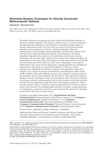
380 Prasant MohapatraFigure 3.Message format and routing in wormhole switching.while routing toward its destination, amessage is stored at an intermediatenode only if the next channel required isoccupied by another packet. Now, thedistance between the source and destination has little effect on communication latency. In an extreme case, when amessage encounters blocking at all theintermediate nodes, the virtual cutthrough technique reduces to packetswitching. The disadvantage of the virtual cut-through technique is its implementation cost: each node must providesufficient buffer space for all the messages passing through it, and becausemultiple messages may be blocked atany node, a very large buffer space isrequired at each node. This implementation constraint limits the use of thevirtual cut-through technique.Wormhole switching is a variant ofthe virtual cut-through technique thatavoids the need for large buffer spaces.In wormhole switching, a packet istransmitted between the nodes in unitsof flits, the smallest units of a messageon which flow control can be performed.The header flit(s) of a message containsall the necessary routing informationand all the other flits contain the dataelements. The flits of the message aretransmitted through the network in apipelined fashion. Since only the headerflit(s) has the routing information, allthe trailing flits follow the header flit(s)contiguously. Flits of two different messages cannot be interleaved at any intermediate node. Successive flits in apacket are pipelined asynchronously inhardware using a handshaking protocol.ACM Computing Surveys, Vol. 30, No. 3, September 1998When the header flit is blocked, then allthe trailing flits occupy the buffers atthe intermediate nodes. The general format of a message and the units of packets and flits are shown in Figure 3(a).Figure 3(b) shows the routing mechanism using wormhole switching, wherethe header flit H contains the destination address and the data flits D followH contiguously in a pipelined fashion.The main advantage of wormholeswitching derives from the pipelinedmessage flow, since transmission latency is insensitive to the distance between the source and destination. Moreover, since the message moves flit by flitacross the network, each node needs tostore only one flit. Some implementations, however, require storage of multiple flits at each node to improve routingperformance. The reduction of buffer requirements at each node has a majoreffect on the cost and size of multicomputer systems.The main disadvantage of wormholeswitching comes from the fact that onlythe header flit has the routing information. If the header flit cannot advance inthe network due to resource contention,all the trailing flits are also blockedalong the path and these blocked messages can block other messages. Thischained blocking can also lead to deadlock where messages wait for each otherin a cycle and hence no message canadvance any further. Prevention ofdeadlock is one of the main issues inwormhole switching, and is usually accomplished by a suitable choice of routing function that selectively prohibits
Computing Surveys 381Figure 4. Performance improvement using virtual channels: (a) packet B is blocked behind packet Awhile all physical channels remain idle; (b) virtual channels provide an additional buffer, allowingpacket B to pass the blocked packet A.messages from taking all the availablepaths, thus preventing cycles in the network. Selection of a routing algorithm isthus a major issue in wormholeswitched networks.3.2 Virtual ChannelsThe primary problem associated withwormhole routing is the blocking ofmessages. A message may be blockedbehind another message destined for anode in a different direction. In Figure4(a), message B, whose destination is inthe east direction, is blocked behindmessage A, which is blocked while traveling in the south direction. This type ofblocking reduces network performancedrastically and can also lead to deadlock. Virtual channels can be used inwormhole-switched networks to preventdeadlock and reduce the effects ofchained blocking [Dally 1992]. A virtualchannel is a logical abstraction of aphysical channel. All the virtual channels associated with a physical channelhave individual flit buffers and aretime-multiplexed for message transmission using the physical channel. Virtualchannels dissociate the buffers associated with the channels from the actualphysical channels. Figure 4(b) showstwo virtual channels associated with aphysical channel in one direction. Evenif message A is blocked by some othermessage down the path, message B canmove forward using the other virtualchannel. Virtual channels reduce theeffect of blocking and are used widely inmulticomputer systems to improve performance as well as to design deadlockfree routing algorithms.Virtual channels are implementedwith a single flit or multiple flits alongwith an appropriate flow-control protocol. The flow-control protocol of a network determines how resources (buffersand channel bandwidth) are allocatedand how message collisions are resolved. A message collision occurs whena packet cannot proceed because thebuffer it needs is held by another message. The flow control strategy allocatesbuffer and channel bandwidth to flits.Because flits have no routing or sequencing information, the allocationmust be done in a manner that keepsthe flits associated with a particularmessage together.3.3 Router CharacteristicsAs wormhole routing is implemented inhardware, the design and characterisACM Computing Surveys, Vol. 30, No. 3, September 1998
382 Prasant MohapatraFigure 5.Block diagram of a wormhole router.tics of the router unit are significant indetermining routing algorithm performance. A detailed study of various design issues related to the routers is reported in Chien [1993]. The primaryfunctions of wormhole routers includeswitching, routing, flow control, multiplexing physical and virtual channels,interchip signaling, and clock recovery.Figure 5 depicts various components ofa generic wormhole router [Chien 1993].The essential components of a wormholerouter and their functionality are described in the following.Crossbar: Crossbar switches enablethe switching of router inputs to outputs. Single or multiple crossbarswitches are used, based on cost-performance tradeoffs. The size of the crossbar may be proportional to the numberof inputs and outputs.Routing Arbitration (RA) Logic: Thislogic unit does arbitration for the routeroutputs. It chooses the path and connects and disconnects the input to anappropriate output based on the routingalgorithm and network status. The complexity and latency incurred in the routing arbitration logic are proportional tothe degree of freedom (number of possible choices) of the routing algorithm.Address Decoder (AD): This unitchecks the message header and generates the set of possible routes based onthe routing algorithm. AD also comACM Computing Surveys, Vol. 30, No. 3, September 1998putes and updates the header information.Flow Control (FC) Units: These unitsare implemented using control logic andbuffers and perform the flow controlbetween the routers. The buffers holdthe flits while flow-control signals arebeing exchanged between the routers.The buffers are also used for holding theflits if a message is blocked.Virtual Channel (VC) Controllers: Virtual channel controllers are implemented in those routers that supportvirtual-channel flow control. These controllers multiplex the physical channelsto provide a set of independent virtualchannels that enables the flow of different messages. The complexity and latency of the controllers increase withthe number of virtual channels due toincreased buffering and arbitration requirements.Messages flow through the routers asfollows. Messages arriving at the routerinputs encounter the address decoder,which checks the message header andgenerates a set of possible outputs forthe message. The routing arbitrationlogic tries to match all the inputs to theoutput channels based on the outputsets generated by the address decoder.If a suitable match is not found for amessage then it is blocked. Once anappropriate output has been selected,the switch connection is made for the
Computing Surveysentire message. The connection is terminated following the last flit.The performance of wormhole routerscan be characterized by two attributes:internal router latency and bandwidth.Internal router latency, defined as thetime to create a valid path through therouter, has contributions from the following factors: address decoding, arbitration, updated header selection, crossbar switching, and virtual channelcontrol delay. The selection policiesused at the routers also have a significant impact on network routing performance. Several input and output selection policies have been compared byGlass and Ni [1992b]. A router’s channel bandwidth depends on the size ofthe flow-control unit (flit) and the timerequired for a flow-control operation.Although higher bandwidth can beachieved by increasing the flit size, sucha choice increases router complexity byintroducing separate logical and physical signaling rates, requiring additionalbuffering, slowing backpressure, and increasing routing latency. The internalflow-control latency limits the flit flowrate in the network channels. Flits areunits of resource multiplexing, so flowcontrol latency determines the network’s ability to share internal connections and external channels amongdifferent packets. The unit of multiplexing directly affects the responsivenessof the network. In addition, flow-controlspeed determines the amount of buffering needed. The flow-control delay includes the latency of flow-control units,the crossbar switch delay, and the virtual channel controller delay.4. WORMHOLE ROUTINGCHARACTERISTICSThe insensitivity to distance, pipelinedflow of messages, and small buffer requirements are some of the main advantages of the wormhole routing scheme.Its primary disadvantage is the
sage tail is absorbed by the destination node. Both start-up and network laten-cies are fixed for a given network. The blocking time of a message is the time spent waiting for a channel currently being used by another message. Thus the blocking time depends on the re-source contentions that a message en-counters in its path. Blocking time can-