Transcription
OPERATING &MAINTENANCEINSTRUCTIONSINSTRUCTION MANUAL IN02Series A & G Diaphragm ActuatorKosoKent IntrolArmytage RoadBrighouseWest YorkshireEnglandPhone: 44 (0) 1484 710311Fax: 44 (0) 1484 407407
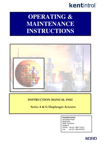
Instruction Manual IN02ACTUATOR REMOVAL OR MAINTENANCEWORK MUST NEVER BE PERFORMED WHENFITTED TO A LIVE VALVEKent IntrolPneumatic ActuatorsSeries A & G Diaphragm ActuatorsSizes 38in², 75in², 150in², 300 in²Spring Opposed andSpringless TypesSeries C Piston/Spring OpposedSeries D Piston/SpringlessSeries A & G Diaphragm Actuators - Spring OpposedTo replace Diaphragm and ‘O’ rings: (See Figs. 1 & 2)General1.Remove the spring cover plate screws and the spring coverplate (541).DIRECT ACTION Actuators (see Fig. 1) extend the actuatorstem with increasing operating air pressure and retract the stemwith decreasing pressure.2.Relieve all spring compression by inserting a ¼” wide barin the spring adjuster (537) slots / holes and rotatingcounter clockwise.REVERSE ACTION Actuators (see Fig. 2) retract the actuatorstem with increasing operating air pressure and extend the stemwith decreasing pressure.3.Remove the diaphragm case screws and nuts (596 & 597)and separate the diaphragm cases.There are upper and lower pads on both sides of the yokesuitable for the mounting of most types of instrumentation.4.Unlock the travel stop nuts (523) and remove them and thetravel indicator pointer (570) from the actuator stem.To remove the actuator from the valve:5.Lift the diaphragm assembly and the actuator stem clear ofthe actuator, taking care to withdraw the stem perfectlystraight to avoid damaging the threads and the ‘O’ rings inthe reverse action arrangement.6.To replace the ‘O’ rings, remove the yoke screws (575) andseparate the yoke (502) from the diaphragm case or springassembly.7.Remove the old ‘O’ rings from the seal box (562) andreplace with new ones.8.To replace diaphragm (555) – unscrew and remove thediaphragm collar nut (544).9.Carefully lift the diaphragm button (553) over the stem,remove and discard the old diaphragm.a)Disconnect all the instrumentation coupling devices fromthe valve stem coupling (23).b)Ensure that the plug face is lifted slightly off the seat (applyair pressure to a reverse acting actuator).c)Carefully remove the coupling bolts (22), separate andremove the two halves of the coupling (23).d)Utilising a drift unscrew and remove the locking ring (25).e)Utilising a straight lift carefully remove the Actuator, takingcare not to damage the valve stem or gland arrangement.f)Before commencing dis-assembly of the actuator removeall instrumentation.10. Slide the new diaphragm (dusted with French chalk orTalc) over the actuator stem into position on the diaphragmcollar (542).Coupling Bolts (22)Stem Coupling (23)11. Replace the diaphragm button (553) and lock the assemblytogether with the collar nut (544).12. To reassemble the Direct Action (Fig. 1) secure the springtube assembly (514) to the yoke (502) by means of theyoke screws (575).To reassemble for Reverse Action (Fig. 2) secure thediaphragm case assembly (517) to the yoke (502) bymeans of the yoke screws (575), ensuring the airconnection is facing the right direction.Locking Ring (25)213. Replace the travel stop tube (551) in its correct position onthe actuator stem (531) – (see Figs. 1 and 2). Slide theactuator stem into position taking care to keep it straight.In the Reverse Action arrangement take care not todamage the diaphragm collar ‘O’ rings (565) – a rotaryaction whilst sliding the stem into position is helpful – Placethe spring (584) over the stem on the diaphragm button(553).
14. In the Direct Action version bolt the diaphragm caseassembly (517) to the spring tube assembly (514) ensuringair connection faces the right direction.In the Reverse Action version slide the stem guide (546) inthe spring tube assembly (514) over the actuator stem(531) and bolt the two diaphragm cases together.15. Replace the two travel stop nuts (523) on the actuator stemwith the travel indicator pointer (570) between them.16. By rotating the spring adjuster (537) clockwise – applycompression to the spring until the actuator stem (531)starts to move at the required air pressure (i.e. 3 or 6 psig)18. Mount the actuator on the valve.a)Pass the yoke over the valve gland and valve bonnetto sit squarely on the bonnet shoulder. Rotate the yokeuntil the windows face in the required direction andthen tighten the locking ring securely.b)With the plug face in contact with the seat and with theactuator stem in its lowest position (apply air pressureto the Direct Action actuator) press the half of the stemcoupling which is threaded for the coupling screwagainst the actuator stem and valve plug stem so that:(i)17. With the diaphragm assembly in its lowest position (applyair pressure for the Direct Action version) adjust the travelstop nuts (523) so that the distance between the top nutand the base of the lower travel stop (524) is the ratedtravel of the actuator or valve (see nameplate) 1/32”. Lockthe nuts together.The ends of the stems are equidistant from thetapped coupling screw holes.and(ii)The tapped coupling screw hole is on the sameside of the actuator as the positioned or otheraccessories, which may require attachment tothe coupling screw.Fig 1 Assembly for Direct ActingSPARES LIST FOR SIZES 75in2, 150in2, 300in2.PART NO.Fig 2 Assembly for Reverse 586587594596597601800NAME OF PARTKel ‘F’ PelletAnti-Rotation PinYokeSpring Tube AssemblyDiaphragm Case AssemblyTravel Stop NutsLower Travel StopSpring Adjusting ScrewActuator StemSpring CarrierSpring Thrust BearingSpring AdjusterCover PlateSpring Cover PlateDiaphragm CollarCollar NutSpringTravel stop tubeDiaphragm ButtonDiaphragmCover Plate JointSeal BoxSeal Box ‘O’ RingsDiaphragm Collar ‘O’ RingTravel Indicator PlateTravel Indicator PointerFelt WiperWiper RetainerYoke ScrewsStem CouplingsStem Coupling ScrewsStem Coupling Screw NutCover Plate ScrewsDiaphragm Cast ScrewsDiaphragm Cast Screw NutsGrub ScrewsCirclipITEMS MARKED * ARE RECOMMENDED SPARES3
Note: It may be necessary to move the plug off its seat by aslight amount in order to mesh the plug stem threads with thelower coupling threads.c)Apply the other half of the coupling carefully engagingthe threads, then insert the coupling screws andtighten by hand.d)Move the plug off the seat by changing the air pressureon the diaphragm then unscrew the plug stem anadditional turn out of the coupling to ensure positiveseating.e)Fully tighten the coupling screws.f)Seat the valve firmly by means of the actuator.g)Adjust the dimension between the lower travel stopand the upper travel stop nut to equal the requiredvalve travel. Position the travel indicator pointer to thenut and lock together with the second travel stop nut.h)Whilst the valve is on its seat adjust the travel indicatorscale so that the shut mark is in line with the travelindicator pointer.By varying the air pressure to the actuator ensure that theassembled unit travels correctly. Ensure that the spring is setcorrectly and adjust as required.THE ACTUATOR IS NOW MOUNTED ON THE VALVE ANDREADY FOR THE FITTING OF ANY INSTRUMENTATION.4
To reverse Actuator ActionKent Introl Series ‘A’ Diaphragm Actuators may be assembledfor either direct or reverse action (see Figs 3 and 4). No extraparts are required and no alterations to components areinvolved, it is simply a question of reassembly of existing parts.7.Remove lower housing screws (639) and lift off screwhousing (605).8.Unscrew Handwheel stem nut (628).9.Withdraw Handwheel Stem (627) complete with worm gear(635) by rotating handwheel stem in anti-clockwisedirection. If thrust bearing (636) does not come out whenthe handwheel stem is removed from the housing take outafter lifting out the worm gear.10.Lift out worm gear (635), screw stem (611) and thrustbearings (637).11.The worm (634) is keyed to the handwheel (627) using asunk key. Normally it should not be necessary to removethe worm; however, this can be done, when required, byholding the worm and lightly tapping the shaft at theopposite end to the handwheel boss.To change the action just simply remove the actuator from thevalve and dismantle it as described above, but there is nonecessity to dismantle the diaphragm assembly or to remove the‘O’ rings from the seal box unless these parts are to be replacedwith new ones.It is necessary, however, to remove the cover plate screws andthe cover plate from the top of the actuator and to unscrew thediaphragm assembly off the actuator stem. Care must be takenbefore attempting to unscrew the diaphragm collar from the stemto loosen adequately the grub screw which locks the diaphragmcollar. Reposition on the actuator stem and screw the diaphragmcollar complete with its diaphragm well home into its newposition and lock it in position by tightening the grub screw.Now reassemble and adjust the actuator as described above.NOTE: In the direct action arrangement, the ‘O’ rings in the sealbox have no function to perform, but they should be left inposition as they will be required if the actuator has to bereassembled for reverse action.SIDE MOUNTED HANDWHEEL UNITCarefully clean and inspect all the components should any showsigns of wear or damage these should be refurbished orreplaced.Re-assembly of Side Mounted Handwheel Unit1.Replace worm (634) on handwheel stem (627), firstensuring that the two well greased thrust washers (636)are in position.2.Apply grease to the screw stem (611) and screw into theworm gear (635) to approximately mid-position.3.Place a well greased thrust bearing (637) on each side ofthe worm gear (635).4.Replace the screw stem/worm gear assembly in the gearhousing.5.Re-engage the worm (634) and worm gear (635) byrotating handwheel stem clockwise as it is replaced in thegear housing6.Replace handwheel stem nut (628) and pack greasearound the worm and wheel7.Replace screw housing (605) on top of the gear housing.(The position of the access windows in the gear housingdoes not affect the functioning of the valve, but foroperating convenience, the travel indicator is usuallyarranged on the same side as the handwheel) fit and fullytighten the lower housing screws (639).8.Replace the handwheel key, the handwheel and fullytighten the handwheel locknut, at this point, check that thecomplete gear assembly rotates freely.9.Refit screw stem nut assembly (630). (See Figs. 7 and 8).GeneralThe Side Mounted Handwheel assembly enables theconventional spring/diaphragm operated Control Valve to bemanually operated in the event of an emergency and also allowsthe valve travel to be limited in either “Open” or “closed”direction.Method of OperationFor normal pneumatic operation of the valve, the handwheel isset in the NEUTRAL position. In this position the valve will movethrough full travel when air pressure is applied to the diaphragm.From the neutral position, CLOCKWISE ROTATION of thehandwheel tends to CLOSE the valve. ANTI-CLOCKWISEROTATION tends to OPEN the valve. The valve may be lockedfull open or fully closed, or the travel limited in any intermediateposition as shown on the handwheel unit travel indicator.REMOVING UNIT FROM THE VALVERemove unit from the valve in a similar manor to removingthe actuator aloneDismantling side mounted handwheel unit (Figs. 3 & 4)1.Set the Handwheel in NEUTRAL POSITION.2.Proceed as for ‘To replace Diaphragm and ‘O’ rings’ up toand including Step 4.3.Remove Actuator Stem Nut (629) by removing the 2 offsocket head cap screws and separating the two halves.4.Remove upper housing screws (639). Ensuring a straightlift and taking great care not to damage the actuator stemlift the actuator off the gear box assembly.5.Unscrew the socket grub screw and taking care not toloose the key (632) remove the handweel (599) – Fig 66.Remove screw stem nut assembly (630) by first releasinglocknut (283) and removing indicator stop peg (620) andthen unscrew nut (641) from screw stem (611)a. Replace screw stem nut (641) on screw stem (611).Top of nut should be approximately level with top ofstem.b. Rotate nut until the screwed hole aligns with the slot inthe screw stem.c. Rotate screw stem and nut together until both holesand slot align with travel indicator window in housing(605).d. Replace indicator peg (620) as shown on Figs. 7 and 8and lock with locknut (283).5
DIRECTACTIONREVERSEACTIONA Assembled for Direct Action.A1 Top Mounted Handwheel forDirect Action.B Assembled for Reverse Action.B1 Top Mounted Handwheel forReverse Action.TOP MOUNTEDHANDWHEELFOR REVERSEACTIONTOP MOUNTED HANDWHEEL FORDIRECT ACTIONSPARES LIST FOR SIZES 38in2SPARES LIST FOR SIZES *2425266DESCRIPTIONScrewCoverSpring AdjusterExtension StemSpring Tube AssemblySpring CapSpring 3-9 PSISpring 3 15 PSISpring 6 30 PSIWasherNutNutWasherDiaphragm ButtonScrewDiaphragmNutDiaphragm Case AssemblyPART lt WiperScrewActuator StemStem Coupling for ValvesAB-16-00110DN ½” – ¾” – 27Stem Coupling for ValvesDN 1½” – 2”ScrewTravel Indicator PlateTravel Indicator e KeyNutScrew SpindleNutTravel Indicator PointerCirclipTrust BearingScrewHousing ScrewStem ConnectorO-RingNutSplit ConnectorStem 48495051PART 50.3110AB5-16-00270211221132111111112111111ITEMS MARKED * ARE RECOMMENDED SPARES
Top Mounted Handwheel and Jacking Screw10.Rotate the handwheel until indicator is in neutral position.11.Taking great care not to damage the stem replace the fullyassembled diaphragm actuator and noting the orientationfit the upper housing screws (639) and fully tighten.General12.If the actuator has not had its spring set then initially adjustthe spring compression by rotating adjuster (537)clockwise until an air pressure of approximately 3 psi isrequired to start the actuator moving,13.a, Reverse Acting ActuatorWith no air pressure on the diaphragm rotate thehandwheel until indicator is below the NEUTRALposition. Replace actuator stem nut (629) onto theactuator stem. Adjust until distance between top of nutand underside of housing is equal to valve travel plus1/ 64 ” and tighten nut onto stem. (Valve Travel is shownon the data plate attached to actuator).b, Director Acting ActuatorFirst apply air pressure until actuator moves throughfull travel and then rotate handwheel until indicator isbelow NEUTRAL position. Replace actuator stem nutand set travel as for Reverse Acting Actuatordescribed above.The KentIntrol Top Mounted Handwheel is in effect acontinuously connected handwheel – top mounted rather thanside mounted. The handwheel is capable of providing operatingforce in both the upwards and downwards direction – it does notrely on the actuator spring to provide return motion. There isnothing to engage or unlatch. It can be used to operate thevalve manually throughout its full stroke, or as a travel stop,limiting the amount of closing or opening of the valve. When setin the neutral position the actuator operates automatically underthe influence of the air pressure and actuator spring. Anindicator is provided to show the position of the handwheelmechanism, and the usual valve travel indicator is also supplied.A locknut is provided to lock the handwheel in any position.Principle of OperationReverse ActingWhen the top mounted handwheel is mounted on a reverseacting actuator – air to open, spring to close – with no airpressure acting on the diaphragm, the handwheel, when turnedin a clockwise direction has no apparent effect on the valve, butis, in fact limiting the valve travel until in the extreme the valve islocked in the ‘closed’ position. When the handwheel is turned inan anti-clockwise direction, the valve stem starts to moveupwards, opening the valve (or limiting the amount of closure)until in the extreme the valve is locked in the ‘open’ position.Direct Acting ActuatorValve Travel 1/64”When the top mounted handwheel is mounted on a direct actingactuator – air to close, spring to open – with no air pressureacting on the diaphragm, the handwheel, when turned in aclockwise direction moves the valve stem downwards closingthe valve and limiting the valve travel until in the extreme thevalve is locked in the ‘closed’ position. When the handwheel isturned in an anti-clockwise direction, no apparent effect isnoticed on the valve until in the extreme the valve is locked inthe ‘open’ position.Dis-assembly of Top Mounted Handwheel14.15.Rotate handwheel until stem nut assembly (630) rises totouch underside of actuator stem nut (629), at the sametime ensuring that actuator stem is not moved upwards.Side mounted handwheel mechanism is now in NEUTRALposition. Check that centre of indicator peg coincides with“NEUTRAL” on the handwheel setting indicator and, if not,correct the error by adjusting the plate accordingly.Refit travel stop nuts (523) and indicator disc (570) so thatthe distance between top of nuts and underside of screwstem is equal to valve travel plug 1/ 16 ”. Check thatindicator disc is aligned with “CLOSED” on travel plate. Ifnot, adjust travel plate accordingly.16.Refit actuator to valve as described on page 1.17.Check that handwheel will fully open or close the valve andthat actuator will move pneumatically through full travelwith handwheel in neutral position.18.Re-check spring compression and adjust as necessary byrotating spring adjuster (537).1.Proceed as for disassembly of diaphragm actuator up toand including Step 3.2.Remove the cover (645) by unscrewing the cheese headscrews.3.Remove the split coupling (584) from stem connector (609)and screw stem (611) by unscrewing coupling screw (586)from stop peg (620).4.Unscrew the socket head capscrews and carefully removethe screw housing assembly.5.The stem connector (609) can now be unscrewed ensuringthat the actuator stem (531) is not allowed to rotate thuspreventing position damage to the diaphragm.6.Remove the circlip and then the indicator pointer (570).7.Rotate the handwheel (599) anti-clockwise to withdraw thescrew spindle (607) and screw stem (611) assembly fromthe screw housing (605). (if jacking screw arrangementremove spindle cover (610) and use spanner squareprovided).8.Remove grub screw from screw plug (613) and removescrew plug from screw spindle, this will allow the screwstem to be withdrawn.9.Remove handwheel lock nut and handwheel.7
Fig. 4 Assembled for reverse actionFig. 3 Assembled for direct actionPART 1553555*559*562564*NAME OF PARTYokeSpring Tube AssemblyDiaphragm Case AssemblyTravel Stop NutsSpring Adjusting ScrewActuator StemSpring CarrierSpring Thrust BearingSpring AdjusterCover PlateSpring Cover PlateDiaphragm CollarCollar NutStem GuideSpringTravel stop tubeDiaphragm ButtonDiaphragmCover Plate JointSeal BoxSeal Box ‘O’ RingsITEMS MARKED * ARE RECOMMENDED SPARES8PART 11629630637638639NAME OF PARTDiaphragm Collar ‘O’ RingTravel Indicator PlateTravel Indicator PointerFelt WiperWiper RetainerYoke ScrewsStem CouplingsStem Coupling ScrewStem Coupling Screw NutCover Plate ScrewsDiaphragm Cast ScrewsDiaphragm Cast Screw NutsGrub ScrewGear HousingScrew HousingScrew StemActuator Stem NutScrew Stem AssemblyWorm Gear Thrust BearingGrease NippleHousing ScrewsITEMS MARKED * ARE RECOMMENDED SPARES
Fig. 6 Section at A-AFig. 5 Handwheel Setting IndicatorPART NO.283*599605611*620627628631632NAME OF PARTLock NutHandwheelScrew HousingScrew StemIndicator-Stop PegHandwheel StemHandwheel Stem NutHandwheel Lock NutHandwheel KeyPART NO.633634635636637638639640641*NAME OF PARTWorm KeyWormWorm GearWorm Thrust BearingWorm Gear Thrust BearingGrease NippleHousing ScrewsHandwheel Indicator PlateScrew Stem NutITEMS MARKED * CONSTITUTE SCREW NUT ASSEMBLY (REF 630)NOTE: Indicator-Stop Peg not to be screwed into location slotfurther than bore of Screw Stem.Plan View in direction of arrow ’A’ (See Fig. 7).Fig. 7Fig. 89
Re-assembly of Top Mounted HandwheelCarefully clean and inspect all the components, any showingsigns of wear or damage should be refurbished or replaced.This is essentially a reversal of the dismantling procedure notingthe following points:1.Screw the stem connector (609) into the actuator stem(531) ensuring that it is hard up against the shoulder andthe actuator stem is prevented from turning. When fitted toDirect Acting actuators care must be taken not to damagethe ‘o’ rings when connector is passed through the sealbox.2.When fitted to Direct Acting Actuator ensure that the wiperring (573) has been soaked it light oil and is fitted inposition in the screw housing (605) with the wiper retainer(574)3.Noting the orientation mount the screw housing (605) overthe stem connector (609) and onto the actuator fit and fullytighten the socket head cap screws.4.Lubricate with grease the 2 thrust washers (621) and placeeach side of the screw stem inside the screw spindle.Screw the screw plug (613) fully into the screw spindle andlock in position with the grub screw.5.Lubricate the screw spindle thread (607) and screw thelocknut (626) on to the handwheel end. Fit the square key,handwheel fit and fully tighten the handwheel locknut.6.Screw the screw spindle assembly into the screw housing.Locate the indicator pin on the screw plug and hold in placewith the circlip.PART NO.NAME OF PARTIndicator PinWiper RingWiper RetainerSplit CouplingCoupling ScrewHandwheelScrew HousingScrew SpindleStem ConnectorSpindle CoverScrew StemScrew PlugStop PegThrust WasherLock NutIndicator Cover 645LockNutSquareKeyLockedOpenNeutral7.Fit the split coupling ensuring that it has maximum hold onthe threads of both the screw stem (611) and the stemconnector (609). Ensure that the stop peg (620) ispositioned in the slot on the screw housing (605) fit andfully tighten the coupling screw (586).8.Refit the indicator cover plate (645)9.Setting of Handjacks in ‘Neutral Position’.a.CirclipReverse Acting ActuatorWith the Actuator in the ‘Down’ position, turn the ScrewSpindle (607) anti-clockwise until the Spring Tension isfelt and the Actuator Stem (531) begins to move.Release this Spring Tension and with the Actuatorback in the ‘Down’ position, the Handjack is now set inthe ‘Neutral’ position (ie. Actuator will operate withoutbeing impeded by Handjack).b.Grub ScrewLockedClosedSocket HeadCap ScrewDirect Acting ActuatorWith the Actuator in the ‘Up’ position, turn the ScrewSpindle (607) clockwise until the Spring Tension is feltand the Actuator Stem (531) begins to move. Releasethis Spring Tension and with the Actuator back in the‘Up’ position, the Handjack is now set in the ‘Neutral’position (ie. Actuator will operate without beingimpeded by Handjack).10. After setting Handjacks, check position of the indicator taband adjust if required11. Utilise locknut (626) if it is required that the handwheel belocked in a position after adjusting.Koso KentIntrol Ltd.Armytage Road,Brighouse, West Yorkshire,England. HD6 1QFTelephone: (01484) 710311.Fax: (01484) 40740710Alternative with Jacking ScrewThe Company’s policy is one of continuous product improvementand the right is reserved to modify the specifications containedherein without notice.Rev1, November 2013
travel indicator pointer (570) from the actuator stem. 5. Lift the diaphragm assembly and the actuator stem clear of the actuator, taking care to withdraw the stem perfectly straight to avoid damaging the threads and the 'O' ringsin the reverse action arrangement. 6. To replace the 'O' rings, remove the yoke screws (575) and