Transcription
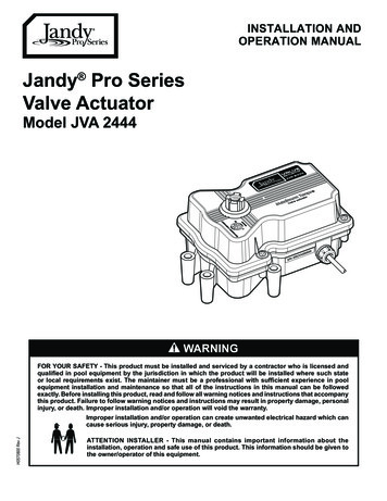
INSTALLATION ANDOPERATION MANUALJandy Pro SeriesValve ActuatorModel JVA 2444WARNINGH0570800 Rev JFOR YOUR SAFETY - This product must be installed and serviced by a contractor who is licensed andqualified in pool equipment by the jurisdiction in which the product will be installed where such stateor local requirements exist. The maintainer must be a professional with sufficient experience in poolequipment installation and maintenance so that all of the instructions in this manual can be followedexactly. Before installing this product, read and follow all warning notices and instructions that accompanythis product. Failure to follow warning notices and instructions may result in property damage, personalinjury, or death. Improper installation and/or operation will void the warranty.Improper installation and/or operation can create unwanted electrical hazard which cancause serious injury, property damage, or death.ATTENTION INSTALLER - This manual contains important information about theinstallation, operation and safe use of this product. This information should be given tothe owner/operator of this equipment.
Page 2ENGLISHJandy Pro Series Valve Actuator Installation and Operation ManualEQUIPMENT INFORMATION RECORDDATE OF INSTALLATIONINSTALLER INFORMATIONINITIAL PRESSURE GAUGE READING (WITH CLEAN FILTER)PUMP MODELHORSEPOWERFILTER MODELSERIAL NUMBERCONTROL PANEL MODELSERIAL NUMBERNOTES:
Jandy Pro Series Valve Actuator Installation and Operation ManualENGLISHPage 3Table of ContentsSection 1. Safety Information. 4Section 7. Wiring Diagrams.11Section 2. General Information. 57.17.27.32.12.2Introduction. 5Description. 5Section 3. JVA Mounting Positions. 53.13.2Standard JVA Position. 5Actuator Mounting. 6Section 4. Synchronization. 74.14.2Synchronization Methods. 7Resetting the Cams. 7Section 5. Manual Operation. 95.15.25.3Manual Override. 9Manual Override, Power On. 9Manual Override, Power Off. 9Section 6. Maintenance. 106.16.2Actuator. 10Valve. 10JVA Wiring Schematic 2444.11JVA's with Toggle Switch.11JVA's with Time Clock.11Section 8. Troubleshooting. 128.1Troubleshooting. 12Section 9. JVA Exploded Viewand Spare Parts. 13
Page 4ENGLISHJandy Pro Series Valve Actuator Installation and Operation ManualSection 1. Safety InformationIMPORTANT SAFETY INSTRUCTIONS PERTAINING TO A RISK OF FIRE,ELECTRIC SHOCK, OR INJURY TO PERSONSREAD AND FOLLOW ALL INSTRUCTIONSWhen installing and using this electrical equipment, basic safety precautions should always be followed, including thefollowing:WARNINGThis manual contains important information about the installation, operation and safe use of this product. Thisinformation should be given to the owner/operator of this equipment.WARNINGThis product must be installed and serviced by professionals who are qualified in pool/spa product installation andservice. Improper installation and/or operation can create an unwanted electrical hazard which can cause seriousinjury, property damage, or death. Improper installation and/or operation will void the warranty.WARNINGDisconnect power to the system at the main circuit breaker before servicing to avoid risk of electric shock which canresult in property damage, severe injury or death. All wiring must be done in accordance with the National ElectricalCode (NEC ), NFPA-70. In Canada, all wiring must be done in accordance with the Canadian Electrical Code(CSA C22.1). All applicable local installation codes and regulations must be followed.SAVE THESE INSTRUCTIONS
Jandy Pro Series Valve Actuator Installation and Operation ManualSection 2. General Information2.1IntroductionThis manual contains information for the properinstallation and operation of Jandy Pro Series ValveActuators (JVA). Procedures in this manual must befollowed exactly. To obtain additional copies of thismanual visit www.zodiacpoolsystems.com. For addressinformation, see back cover.2.2ENGLISHSection 3. JVA MountingPositions3.1Standard JVA PositionStandard Plumbing position is with the middle port(B) as the incoming or common port to the valve (seeFigure 1).Remove thesefour (4) screws forStandard PositionDescriptionValve Actuators are designed to meet the needs oftoday's more advanced, automatic pool equipment.These fully adjustable actuators offer versatile pool/spaautomation with easy setups. All actuators work withAquaLink RS Control Systems and are available in 24volt units.JVA 2444 SpecificationsVoltage24 VACAmperage0.75 AMPSCycles60 HzWireBlackRedWhite3-conductorCommonSwitch LegSwitch LegPage 5ACWater flow into orout of the valveB (Common Port)Figure 1. Standard PlumbingStandard Mounting position is with the main body ofthe actuator over port B (see Figure 2).NOTE If the valve(s) are plumbed with port B as thecommon port (Standard Plumbing) and the mainbody of the actuator(s) are mounted over port B(Standard Mounting), there is no need to adjust theactuator cams.ACB (Common Port)Figure 2. Standard JVA Mounting
Page 63.2Jandy Pro Series Valve Actuator Installation and Operation ManualENGLISHActuator Mounting3.JVA’s mount directly on all full-size Jandy ProSeries Valves (8 screws on lid). Zodiac recommendsmotorizing Jandy Pro Series Never Lube Valves only.JVA’s may be mounted onto valves in any of the four (4)positions in Figure 3.IAPlace actuator on valve so smallest toothaligns with smallest slot.IIATurn the actuator over so you can see into theclear actuator shaft. There are four (4) "teeth"on the inside of the shaft. Locate the smallest"tooth" and align this "tooth" with the smallestslot on the valve (see Figure 5).Smallest SlotSmallest ToothCCBActuatorBottomBIIIIVFigure 5. Actuator MountingACAC4.Place the actuator onto the valve.5.Rotate the actuator while keeping the two shaftsengaged until the screw holes on the actuator legsalign with the empty screw holes (from step 2) inthe valve (see Figure 6).6.Use the four (4) large 2" Phillips head screws(included with the JVA) to secure the JVA to thevalve.7.Put the valve handle on the actuator shaft. Putthe knob on the shaft and tighten (finger tightenonly).BBFigure 3. JVA Mounting Positions.1.Unscrew the locking knob by turning the knobcounterclockwise. Remove the locking knob andvalve handle (see Figure 4).2.For standard valves, remove the four (4)large Phillips head screws from the valve.The location of the screws you remove willdetermine how the actuator will be mounted(see Figure 4). When installing the large 3"valve, it is not necessary to remove any screws.Use the four mounting bosses provided.Remove LockingKnob and HandleRotate valve or actuatorto align screw holesRotatevalveRemove the 4 LargePhillips Head ScrewsRotateactuatorFigure 6. Actuator MountingFigure 4. Remove Locking Knob and Lid Screws
Jandy Pro Series Valve Actuator Installation and Operation ManualSection 4. Synchronization4.1ON 1Synchronization MethodsOFFIf the valve is plumbed in the Standard Plumbingposition and the actuator is mounted in StandardMounting position, you do not have to change the camsettings from the factory settings. However, you mayhave to synchronize the cams.One of the following will occur when the actuator is outof synchronization: the actuator will rotate in the wrong directionin relation to its controller (as in a solar heatingsystem) one actuator will rotate incorrectly in relation toanother actuator (as in pool/spa combination)Figure 7 illustrates an example of the valves andactuators of a pool/spa combination that are out ofsynchronization. The valve on the left of the illustration(suction) is plumbed with the spa line on the left sideof the valve and the pool line on the right; whereas, thevalve on the right of the illustration (return) is plumbedwith the pool on the left side of the valve and the spaon the right. In this configuration, if the actuators areactivated, one will turn to spa while the other will turnto pool. The actuators will have to be synchronized.SuctionSpaENGLISHON 2Page 7On/Off Switch islocated on thebottom of the JVAFigure 8. JVA Synchronization, Toggle4.2Resetting the CamsWARNINGImproper cam settings can result in dead headingof the water flow which can cause injury or propertydamage. Improper cam settings and/or operation willvoid the warranty.NOTE Before resetting cams, if the valve is plumbed inStandard Plumbing position and the actuator is inStandard Mounting position there is no need forresetting the cams (see Figure 9). If a port other than"B" is plumbed as the common port or if the actuatoris mounted other than Standard Mounting, the camsetting must be changed so the actuator shaft andthe valve diverter rotate properly. Refer to the CamSetting Chart on page 8 for proper re 7. JVA Synchronization, ExampleOn the actuator that is out of synchronization, flip thetoggle switch located on the bottom of the actuator tothe ON 2 position (see Figure 8). The toggle positionsare marked on the actuator top cover. Retry the system.Figure 9. JVA Mounting Positions.1.Turn OFF actuator power. Unscrewthe locking knob by turning the knobcounterclockwise. Remove the locking knoband valve handle.2.Remove the four (4) Phillips head screws thatsecure the actuator lid and then remove the lid.
Page 83.Jandy Pro Series Valve Actuator Installation and Operation ManualENGLISHImportant - Rotate the actuator shaft so thearrow mark on the top cam aligns with themicroswitch actuator (bottom cam arrow markshould also align with the bottom microswitchactuator, see Figure 10). Locate the mountingposition for the actuator (as per Figure 9, themounting position will be either I, II, III, or IV).Next, determine what valve port is the commonor inlet port (as per Figure 9, the common portwill be either A, B, or C). Then refer to theCam Setting Chart below to determine whatthe cam settings should be. For example, if theactuator is in JVA mounting position "I", and thecommon port on the valve is port "A", the camsettings would be 90 for the top cam and 180 for the bottom.NOTE The cam is marked with the arrow at "0", a long hashmark at the 180 position, and 2 short hash marks atthe 90 and 270 positions.4.To set the cams, rotate the cam(s) until thearrow mark on the cam(s) align with themicroswitch actuator (see Figure 11).NOTE The upper cam stops counterclockwise rotation andthe lower cam stops clockwise rotation.5.Turn power ON to the actuator and use thetoggle switch located on the bottom of theactuator to check rotation. Move the toggleswitch to either ON 1 or ON 2. Allow theactuator shaft to move until it stops. Checkvalve diverter position*, if the position iscorrect flip the toggle switch in the oppositedirection and allow the shaft to stop again. Ifthe stop positions are correct, go to step 6. Ifthey are not, reset the cams until correct.Final minor adjustments may be necessaryLowerCamUpperCamNOTE If the actuator does not move in either direction, referto Section 6, Troubleshooting.180 6.270 NOTE The end of the handle which has the word OFF90 00LeftMicroswitch0 Replace the lid and tighten screws. Replace thehandle and locking knob.embossed on it exactly duplicates the shape of thevalve diverter. When the handle is placed on a valveor actuator shaft the word OFF will be directly overthe center of the valve diverter.RightMicroswitchFigure 10. JVA CamsCam Setting ChartNOTE Before resetting cams, always rotate the actuator shaft so the arrow mark on each cam aligns with the pointer above itsmicroswitch.ActuatorMountingWater Enters PortCommon Port*IACam SettingTop CamBottom CamWater Exits B*IVA0270BCIVB180180ACIVC2700AB*Two Port Valve Settings
Jandy Pro Series Valve Actuator Installation and Operation Manual5.3Rotate CamsFigure 11. JVA Cam AdjustmentManual OverrideIt is sometimes necessary to rotate valve(s) manually,without using the system controller. This occurs whenthe controller is not accessible/operational or when thespa or pool/spa combination require filling or draining.There are two (2) methods of manually rotating theJVA; one with power on (system operational) and onewith power off (no power to the control system).CAUTIONTo prevent damage to your equipment and tominimize the possibility of any injury resulting fromsuch damage, make sure that the pool filtration pumpis OFF BEFORE rotating the valve handle.5.2Manual Override, Power On1.Move the toggle switch located on the bottomof the actuator to the opposite position (ON 1switch to ON 2 or vice versa). This will rotatethe motor to the opposite position.2.Return the toggle switch to the original positionafter use.ON 1OFFOn/Off Switch ison Bottom of JVAON 2Figure 12. JVA Synchronization, TogglePage 9Manual Override, Power Off1.Move toggle switch located on the bottom ofactuator to the OFF (center) position.2.Unscrew (counterclockwise) the locking knobabove the handle four (4) full turns.3.Push down on the locking knob (not thehandle). This will disengage the gear train andallow the handle, and thus the valve diverter, tobe moved to any position.4.To return the actuator to automatic position, pullup on the handle while turning it clockwise orcounterclockwise until you feel the shaft slideup into the gear train. Turn the locking knobdown (clockwise) until snug.5.Put toggle switch back to the original position.Section 5. Manual Operation5.1ENGLISH
Page 10Jandy Pro Series Valve Actuator Installation and Operation ManualENGLISHSection 6. Maintenance6.16.2ValveNOTE This section does not apply to Jandy Pro SeriesActuatorThe JVA has three (3) seals which should be lubricatedonce a year. One o-ring is located on the bottom of theactuator where the plastic shaft exits the housing andtwo (2) O-rings located in the top cover near where theshaft exits the top of the housing. Use the followingsteps to lubricate the seals:1.Turn OFF power to the actuator.2.Remove the locking knob and handle(see Figure 13).Unscrew lockingknob and removehandleLubricate hereNever Lube Valves and non-positive seal valves.Never Lube Valves and non-positive seal valves canbe identified by the absence of a grease cap. NeverLube Valves can also be identified by the name"Never Lube" on the handle.Since the actuator rotates the valve diverter whichredirects the flow of water, it is imperative that the sealsand the O-rings within the valve body be lubricatedoften (at least every three (3) months). Use thefollowing procedure to lubricate the valve diverter seals:1.Turn off all pool/spa equipment.2.Rotate valve handle so the OFF on the handle isover the word GREASE on the valve body.3.Unscrew (counterclockwise) and remove theblack cap of the grease fitting.4.Fill cap with lubricant (Jandy Lube).5.Replace cap on fitting and turn in (clockwise)until all of the lubricant has been forced into thevalve.6.Use manual operation to move the handle fromside to side to spread the lubricant across theseal.7.Reset the valve handle to its original positionand start the equipment.Once a year the valve should be disassembled andthe O-ring and valve body inspected for damage.Thoroughly lubricate the square seal and the O-ring.Reassemble the valve.Figure 13. JVA Shaft Seal3.Spread a small amount of Jandy Pro SeriesLube or other silicone base lubricant around theactuator shaft just above the lock out ring (seeFigure 13).4.Reinstall handle and locking knob. Only tightenknob one (1) turn.5.Push down on the locking knob to force theactuator shaft into manual.6.Wipe a small amount of lubricant around theactuator shaft where it protrudes from thebottom of the actuator.7.Turn handle once around to spread the lubricant.8.Pull up on the handle and tighten locking knob.
Jandy Pro Series Valve Actuator Installation and Operation ManualENGLISHPage 11Section 7. Wiring DiagramsRightMicro switchLeftMicro switchCommonCommonNOWARNINGNCBottom CamMotorConnectorto PCBHeaderPOWERCAUTIONTo avoid damage to the equipment and minimizerisk of injury, use a properly sized, listed Class 2transformer for connection to the power supply.NCRedRedDisconnect power to the system at the main circuitbreaker before servicing to avoid risk of electric shockwhich can result in property damage, severe injuryor death. All wiring must be done in accordance withthe National Electrical Code (NEC ), NFPA-70.In Canada, all wiring must be done in accordancewith the Canadian Electrical Code (CSA C22.1). Allapplicable local installation codes and regulationsmust be followed.NOWhiteJVA Wiring Schematic 2444White7.1RedBlackRedWhiteRedWhiteTop CamMotorConnectorto PCBHeaderWhiteBlackBlackBlackWiring to ToggleSwitch UnderneathCircuit BoardPCB Header for Motor WiringJVA's with Toggle SwitchTransformer*Secondary(24 VAC)7.3JVA's with Time ClockThis diagram is for a single JVA 2444.To operate more JVA's, additional poles and a higheramperage fuse are needed. Do not double lug the JVAswitch leg wires (red and white wires).Primary(120 VAC)TimeClock1 ampfuseWHITEBLACKBLACKNormally ClosedCommonNormally OpenWHITEOFFPrimary(120 VAC)OFF* Transformer must be sized for the number of JVA's.Each JVA requires .75 amp. at 24 VAC.Single Pole/Double ThrowRelayCoil Voltage: 120 VACNeutralSecondary(24 VAC)REDNormally ClosedCommonNormally OpenRED120 VAC2 ampfuseHotDouble Pole/Double ThrowToggle SwitchNeutralTransformer*LoadThis diagram is for two (2) JVA 2444s.To operate more JVA's, additional poles and a higheramperage fuse are needed. Do not double lug the JVAswitch leg wires (red and white wires).Line7.2120 VACREDWHITEBLACKOFF* Transformer must be sized for the number of JVA's.Each JVA requires .75 amp. at 24 VAC.
Page 12ENGLISHJandy Pro Series Valve Actuator Installation and Operation ManualSection 8. Troubleshooting8.1TroubleshootingAll major components, including the power cord, are replaceable without replacing the entire actuator. Each item maybe replaced as a separate piece allowing easy infield repair. See Section 8, Exploded Views and Replacement Kits, foractuator replacement part numbers.ProblemActuator handle oscillates.CauseLack of valve seal lubrication.Obstruction in valve body.Actuator motor works but the valvediverter does not turn.A). Actuator shaft broken.NOTE On a pool/spa combination,B). Valve diverter broken.the problem would be spa draining or C). Actuator in manual position.overflowing.D). Gear train damaged.Actuator motor does not turn.A) No power to the actuator.B) Toggle switch in OFF position.Actuator rotates in one direction butnot back again.Water inside valve actuator.C) Motor has failed.D) Failed or broken microswitch.E) Both cams in contact with theirmicroswitches.A) Broken or damaged micro-switch.B) Bad connection(s).C) Bad control relay switch.D) Broken wire.Damaged seals.Solution/CheckLubricate valve.Remove actuator and valve lid andinspect.A). Replace actuator shaft. Refer toShaft Replacement Kitinstructions for disassembly.B). Replace valve diverter.C). Pull up on the handle whilerotating counterclockwise.D). Refer to Gear Replacement Kitinstructions for disassembly.A) Check voltage between black(common) wire and each switchleg (red then white)B) Move toggle switch to ON 1 orON 2 position.C) Replace motor.D) Replace microswitch.E) Check Cam Setting section.A) Replace microswitch.B) Check all connections.C) At the power source check theoperation of the control relay orswitch.D) Check red and white wires.Replace top lid and grease seals.
Jandy Pro Series Valve Actuator Installation and Operation ManualENGLISHPage 13Section 9. JVA Exploded View and Spare PartsDwg.#Kit 800R0411900R0441700R0408500R0408600333, 73, 81111176111153,833311113414Motor KitScrew, #8 x 5/8"Motor 24V, w/Wire andConnector81, 2, 3PCB w/Toggle Switch KitPCB Sub-Assy, 24V w/PCB,w/Toggle Switch, LockWasher and Nut7281112111Cable Kit, 75'O-ring, Strain ReliefWasher, Strain ReliefCap, Strain ReliefPower Cord, 75' w/3-pinConnector61, 2Cable Kit, 20'O-ring, Strain ReliefWasher, Strain ReliefCap, Strain ReliefPower Cord, 20' w/3-pinConnector521241Gear KitPrimary GearSecondary GearLarge Pinion GearOutput GearHousing, Bottom w/3 Pins51, 2Center Plate KitO-ringScrew, #8 x 5/8"BridgeTop Cam (Clear)Bottom Cam (Textured)MicroswitchCenter PlateOutput Shaft, ThreadedSpring, JVA41244Top Housing KitGasketO-ringScrew, #8 x 5/8"Housing, Top31JVA Gasket and Screw KitGasketO-ring,Screw, #14 x 2"Screw, #8 x 5/8"2Qty.113Cam and Microswitch KitTop Cam (Clear)Bottom Cam (Textured)Microswitch6112
Page 14ENGLISHJandy Pro Series Valve Actuator Installation and Operation ManualNOTES
Jandy Pro Series Valve Actuator Installation and Operation ManualNOTESENGLISHPage 15
Zodiac Group Australia.219 Woodpark RoadSmithfield, NSW AU 21641.800.688.552 www.Zodiac.com.auZodiac Pool Systems, Inc.2620 Commerce Way, Vista, CA 920811.800.822.7933 www.ZodiacPoolSystems.com 2016 Zodiac Pool Systems, Inc. ZODIAC is a registered trademark of Zodiac International,S.A.S.U., used under license. All trademarks referenced herein are the property of their respectiveowners.H0570800 Rev JETL LISTED CONFORMS TOUL-STD 1563CERTIFIED TO CAN/CSA C22.2 NO.218.1
the actuator over port B (see Figure 2). NOTE If the valve(s) are plumbed with port B as the common port (Standard Plumbing) and the main body of the actuator(s) are mounted over port B (Standard Mounting), there is no need to adjust the actuator cams. Jandy Pro Series Valve Actuator Installation and Operation Manual ENGLISH Page 5